• The Roadster Factory Recovery Fund - Friends, as you may have heard, The Roadster Factory, a respected British Car Parts business in PA, suffered a total loss in a fire on Christmas Day. Read about it, discuss or ask questions >> HERE. The Triumph Register of America is sponsoring a fund raiser to help TRF get back on their feet. If you can help, vist >> their GoFundMe page.
  • Hey there Guest!
    If you enjoy BCF and find our forum a useful resource, if you appreciate not having ads pop up all over the place and you want to ensure we can stay online - Please consider supporting with an "optional" low-cost annual subscription.
    **Upgrade Now**
    (PS: Subscribers don't see this UGLY banner)
Tips
Tips

Installing wire tips

M

Member 10617

Guest
Guest
Offline
Some of my wire connectors and wire tips could stand replacing. When replacing wire tips, I assume they are soldered and not pinched onto the wire ends. Any tips on how to install these most effectively and securely?
 

Don Elliott

Obi Wan
Offline
There were two types - solder-on and later crimp-on bayonet conectors. All the bayonets on my 1958 TR3A (TS 27489 LO - very close to your TR) are the solder-on type. If yours are soldered onto the ends of the stranded wires, all you have to is heat up the tip of your hand soldering iron, wet the tip of the iron by melting a bit of solder using a heated iron and a touch on rosin-core fluxed wire solder (63/37) marked on the roll = 63% tin and 37% lead. Then hold the tip of the iron at the bullet nose end of the bayonet connector and the solder will melt. Pull off the bayonet with long nose pliers, dress up the stranded wires or clip off about 1/16" from the end for a clean finish. Then reinsert the stranded wire with the vinyl removed back to the open big end of the bayonet. Insert the starnded wire. If it won't go in and you can't see it in the small hole at the front "bullet end", heat up the bare bayonet holding it with your long-nose pliers. When you see that the solder has all melted, rap it on the work bench and the remaining liquid solder will fly out - careful - it will be hot above 361 degrees F and it will be liquid so it might splash around a bit. You don't want any solder to land on your hand, arm or face. Also don't wear any synthetic shirts etc. because molten solder will melt the synthetic material and it will all fuse to your skin and no-one enjoys that happening.

Now you have reinserted the stranded wire into the big end of the bayonet and you can see the tip of the strands coming up through the tiny hole at the bullet end. Or at least you can see the stranded end just below - looking down the tiny hole.

Hold it securely (don't crush it) in a vice and using your hot soldering iron tip and some fresh rosin-core 63/37 wire solder, re-solder the tip of the bayonet. The solder will melt on the bullet tip end of the bayonet and will run down inside the tiny hole by capillary action - then move the soldering tip away and let the wire, connector and hot solder cool till it is solidly soldered before you remove it from the vice.

Now you have most of the story about soldered bayonet ends for your TR standed wires.

If the soldring iron does nothing as the first step, your connectors are probably the crimped-on type. I don't know anything about these.

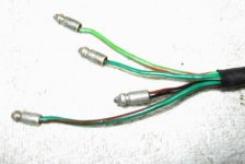
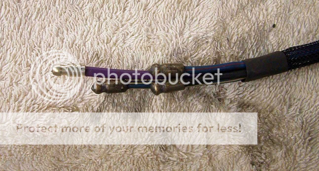
Below is a photo of the staggered solder-on bayonets you will find at the bottom end of the steering column. These connectors were soldered on in 1958.
 

Attachments

  • 24005.jpg
    24005.jpg
    46.7 KB · Views: 381
OP
T

Tinster

Guest
Guest
Offline
LexTR3 said:
Some of my wire connectors and wire tips could stand replacing. When replacing wire tips, I assume they are soldered and not pinched onto the wire ends. Any tips on how to install these most effectively and securely?

I know zip about the wiring in a TR3. I DID rewire my entire '69 TR6 myself. My connectors are all bullets which I crimped and then soldered. A special crimping tool and bullet pliers are required. I used a mini-butane torch to solder.
I also crimped and soldered terminal ends.

https://www.advanceautowire.com/

Visit Advance Auto Wire to get you started.
Click on "Instruction Manuals" left side of page.
Find your car. There are photos of the bullet crimping tool
as well as soldering instructions. The recommended $50 crimping tool is amazing. It has many, many uses around the garage and home. The bullet pliers are a must. You make yourself crazy if you try to use channel lock pliers.
 

TR3driver

Great Pumpkin - R.I.P
Offline
Just to echo, I feel that crimped + soldered is the most secure. That said, my TRs have only been soldered and I've never had any trouble with bullets.

Note that when using only solder, the bullet needs to fit snugly around the wire, so the solder will fill the gap all the way around. In some cases, where I was using AWG-sized wire, I wound up using a smaller size bullet and drilling it out to fit the wire. If you are only doing a few of them, it may be simpler to just buy the smallest bullet and drill it out to suit.

Three of these are original to my 56 TR3, the other is new:

Oneextrawire.jpg
 

KVH

Darth Vader
Country flag
Offline
Don Elliott said:
The solder will melt on the bullet tip end of the bayonet and will run down inside the tiny hole by capillary action - then move the soldering tip away and let the wire, connector and hot solder cool till it is solidly soldered before you remove it from the vice.

Three questions. First, from the quote, assuming the bullet is horizontal, and some gap exists between the wire gauge and the inside sleeve/casing of the bullet, will capillary action fill it?

Second, if you solder and crimp as suggested, do the bullets just crimp with a standard crimping tool?

Finally, I assume the staggering of the wire lengths is to facilitate sliding the wires into the steering tube and avoiding a "bunch" under the dash. I forgot to do that when I rewired mine.
 

TR3driver

Great Pumpkin - R.I.P
Offline
KVH said:
assuming the bullet is horizontal, and some gap exists between the wire gauge and the inside sleeve/casing of the bullet, will capillary action fill it?
Only if the gap is very small.
<div class="ubbcode-block"><div class="ubbcode-header">Quote:]Second, if you solder and crimp as suggested, do the bullets just crimp with a standard crimping tool?[/QUOTE]No, it's a special tool just for British bullets.
https://www.britishwiring.com/CAT28_29.PDF
<div class="ubbcode-block"><div class="ubbcode-header">Quote:]
Finally, I assume the staggering of the wire lengths is to facilitate sliding the wires into the steering tube [/QUOTE]
"Facilitate" isn't a strong enough word, IMO. If the bullets line up, they won't fit through the tube at all. Note that the heavy horn wire also needs to be the shortest.

But the control head harness doesn't protrude under the dash, so that's not an issue.
 

KVH

Darth Vader
Country flag
Offline
Randall, thanks. About the horn wire. I think that when I replaced it (mine was in bad shape)I just put a 16 gauge back in there. Does it really need to be thicker than the others?

Also, I do like that British Wiring crimping tool, but another $50 plus shipping could provoke the ire of "the boss of me."
 
OP
T

Tinster

Guest
Guest
Offline
You need to do something very, very nice for the boss.
IMO- the British crimping tool is a "must have" for reliable
bullet to wire connections. Also, it makes soldering the bullet ever so easy.

Crimp the bullet, hold the wire in the crimper so the bullet is vertical and then solder it.

You will not regret the investment. Might find one on E-Bay.

good luck
 
OP
M

Member 10617

Guest
Guest
Offline
Hi, Guys,

Many, thanks for all this great information. Don's step by step instructions are the kind of guidance we of little experience need. I will try to find a British crimping tool at Lowe's and give all this a try.
 

hondo402000

Darth Vader
Offline
FYI there are also some spade connectors in there too, the wiper switch, the washer switch, fan switch all have spade connectors and some to the reverse light switch and OD switches, I know because I am in the process of rewiring my 71 TR6 also the hazzard switch has spade connectors, those should be easier to get and to replace oooo and all the gauges have spade connectors


Hondo
 

Brinkerhoff

Jedi Knight
Offline
Guys, with all due respect don't waste your time and money buying a special crimping tool. The bullets were ALL soldered from the factory on the 50s & 60s cars. I reuses old bullets by drilling out the old wire , dipping a stripped end in flux , sliding it in the bullet until the end just protrudes, support it in the bench vise and heat it with a small pencil butane torch, then let a small amount of acid core solder melt in to it. If your good you'll leave a nice solder cone . That type of connector is to be soldered , not crimped, as you may distort the case so it won't slide all of the way in to its tube. As long as your solder connection is "hot" there is no need to crimp. Have fun , keep your money. Kevin
 
OP
M

Member 10617

Guest
Guest
Offline
A couple of technical questions:

1. Thanks Binkerhoff. But here is a question. I was always told that acid core solder is not for electrical soldering, but that I must use rosin core solder. do you recommend acid core solder.

2. Don. You say that I should use rosin-core fluxed wire solder (63% tin and 37% lead). Problem is that all the solder available around here (and I believe elsewhere) is now "lead free") I think they've taken the lead solder off the market. So happens, however, that I have some from many years ago and it is rosin core 40% tin and 60% lead (low melting, 1/16 in. dia.) Can that be used instead of what you recommended?

UPDATE: Radio Shack may have 60/40 solder. I'll check.
 

KVH

Darth Vader
Country flag
Offline
It seems to me that the best would be a combination of solder and crimping, since that's what the factory appears to have done.

I think the key is to have the correct size for the bullet in relation to the wire gauge so that a decent crimp at the end would strengthen the end result.
 

Don Elliott

Obi Wan
Offline
Hondo - Spade connectors only started to be used by Standard Triumph on the later TR3As with Comm. nos after TS 60000. My early TR3A as well as the owner who asked the first question on this topic both have very early TR3As and on my 1958 TR3A, I do not have a single spade connector that was on the car from new.

Don Elliott, Original Owner
 

TR3driver

Great Pumpkin - R.I.P
Offline
KVH said:
Does it really need to be thicker than the others?
Probably not, but those early horns do draw a lot of current (on a very intermittent basis).
 

TR3driver

Great Pumpkin - R.I.P
Offline
LexTR3 said:
Problem is that all the solder available around here (and I believe elsewhere) is now "lead free") I think they've taken the lead solder off the market.
Should be readily available from any decent electronics shop (which may or may not include the one you mentioned). Here's one on-line source:
https://electronics.mcmelectronics.com/search.php?N=4294967272+4294966927+4294966912&Ns=0
<div class="ubbcode-block"><div class="ubbcode-header">Quote:] So happens, however, that I have some from many years ago and it is rosin core 40% tin and 60% lead (low melting, 1/16 in. dia.) Can that be used instead of what you recommended?[/QUOTE]
60/40 rosin core will work just dandy!

Acid core solder on copper wire is a Bad Idea, if you care if the connection still works 10 years from now. If you only care if it works until the car is out of your shop, then acid-core is fine. (You might even get some repeat business that way :cryin: )

FWIW, I believe that if you are finding joints that have been both crimped and soldered, then some amateur has been at work. On the early cars, the factory only used solder; some later connections were crimp-only. They weren't real big on the "belt and suspenders" approach.
 
OP
M

Member 10617

Guest
Guest
Offline
One more related question: What is the best way to remove the wire and bullet from an old female connector, especially if the bullet/wire have been in there 50 years? I want to inspect the bullet/wire connection and replace it, but only if I have to.

What if I were to remove the female connector altogether by wedging it apart, then check both wire and bullets and insert them into a new female connector?

BTW and for what it is worth, Williams, in How to Restore Triumph, on p. 150, writes: "For maximum longevity, first crimp any electrical terminations you renew, then solder the crimped termination."
 

angelfj1

Yoda
Country flag
Offline
LexTR3 said:
One more related question: What is the best way to remove the wire and bullet from an old female connector, especially if the bullet/wire have been in there 50 years? I want to inspect the bullet/wire connection and replace it, but only if I have to.

What if I were to remove the female connector altogether by wedging it apart, then check both wire and bullets and insert them into a new female connector?

BTW and for what it is worth, Williams, in How to Restore Triumph, on p. 150, writes: "For maximum longevity, first crimp any electrical terminations you renew, then solder the crimped termination."

Ed: This is what I do. I use two needle nose pliers. I secure the metal shell (female) with one and the bullet(male) with the other, and pull. They should come apart. I use a fine wire wheel in my electric drill or Dremel to clean the bullet and emery cloth wrapped around a small dowel for the shell. After cleaning them, apply a thin coating of dielectric grease and push the bullet home. You may have to squash the shell a little for a snug fit. To prevent stressing the wire, use the pliers to push the bullet into the shell. Now, pull on the wires. The connection should not come apart easily.

If you find severe corrosion and can't get the connectors apart, cut the wires and use a new pair of bullets and a new shell. BTW, I always crimp first and then solder using a good quality, 60/40, rosin-core solder.

Good luck
 
OP
M

Member 10617

Guest
Guest
Offline
Frank,

Just what I needed. Many thanks. I expect I'll have to cut a few of those old wires and install new bullets, but I hope most will come out of the female connectors without too much trouble.

Dielectric grease! Yes, indeed. This is why I am taking apart many of my connections. I want to treat every one with the grease that I can. It is great stuff and keeps the connections corrosion free for years.

BTW. A friend of mine cautioned me a couple of days to use dielectric grease but never dielectric paste. Dielectric grease, as you know, is an insulator (although it doesn't stop current in your connections), but dielectric paste contains metal particles and current can flow through it to where you don't want it and short your your system.
 

TR3driver

Great Pumpkin - R.I.P
Offline
angelfj said:
I use a fine wire wheel in my electric drill or Dremel to clean the bullet and emery cloth wrapped around a small dowel for the shell.
After fighting several problems caused by the contacts inside the shell being loose and/or broken, I just replaced them all. At about $1 each, it seems like cheap insurance to me.

The only exception would be the 6-way shells, which seem to be NLA. I just replaced mine with three 2-ways, but for strict originality you might want to keep the 6-ways. Even then, I think I'd be tempted to try to extract and replace the contacts.
 
Similar threads
Thread starter Title Forum Replies Date
J Installing Adapter Hubs for Wire Wheels on a Bugeye Austin Healey 5
S Installing a Radiator Fan Austin Healey 9
G Installing New Rocker Shaft Assembly Austin Healey 3
W Need advice on installing new side curtain glass Spridgets 1
Bayless Help please installing bonnet release cable Spridgets 8
M TR6 Installing Retrosound? Triumph 4
S TR2/3/3A Installing the distributor pedestal. Triumph 3
K TR2/3/3A Question about installing the steering wheel control head? Triumph 1
A TR6 Installing differential and transmission Triumph 10
Z Installing Toe Board Panels Austin Healey 1
K TR2/3/3A Installing Brake Caliper pistons into the bore? Triumph 21
CJ Burton MGB-GT Installing Seat Covers for 1962 - 1967 MGB GT MG 0
A Early 1967 AH Sprite - installing steering column and new directional switch? Spridgets 0
B Installing cam bearings 1275, can I do it? Spridgets 1
bighealeysource Installing stainless steel brake hose on BN2 Austin Healey 5
steveg TR6 Installing stock trailing arm bushings on the car - is it possible? Triumph 2
steveg TR6 Installing adjustable trailing arm brackets Triumph 7
T Installing Garmin GPS in a BJ7 Austin Healey 19
F Installing AC in my 1960 Healey Austin Healey 14
S TR2/3/3A technique for installing a door Triumph 5
R TR2/3/3A Installing wiring harness in steering column Triumph 59
R TR2/3/3A Installing gas tank Triumph 6
C Installing rubber grommets in firewall? Austin Healey 6
S TR2/3/3A installing a fuse in the red tail lights Triumph 4
S TR2/3/3A installing the wiring harness Triumph 8
R Installing Sprite Luggage Rack Spridgets 9
Lukens TR2/3/3A Installing a throttle. Triumph 2
J Powertune booster for a bj8 , trouble installing Austin Healey 2
B TR2/3/3A Installing dzus fastners in bonnet Triumph 8
D Prepping Floors Before Installing Interior Restoration & Tools 6
drooartz Installing front hubs, tips? Spridgets 15
E TR4/4A Wiring the horn when installing a Moto -Lita steering wheel Triumph 4
K TR2/3/3A Installing Moss wheel spacers? Triumph 5
D BT7 tri-carb installing my crank Austin Healey 4
aero3113 Installing Front rotors to hubs Austin Healey 2
C Advice for installing a 3000 Grille??? Austin Healey 7
B MGB Installing new upper fulcrum bushings MG 5
B MGB Installing upper fulcrum bushings MG 0
S TR4/4A procedure for installing gauges etc Triumph 0
I Tips for installing intake manifold plugs in a stock Bugeye? Spridgets 6
55modified Help installing toggle dip switch on dash for lights. Austin Healey 23
TRMark TR4/4A Installing a new windscreen Triumph 9
55modified Rear anti-roll bar. Is it worth installing on a BN1? Austin Healey 22
T Installing a Lucas 16 ACR alternator on Bugeye Spridgets 10
KVH General Tech Installing the Pistons and Rings Triumph 7
T Need advice for installing a Winner's Circle Panhard rod on a BE Spridgets 4
6 General Tech Installing New Oil Pressure Gauge MG 5
6 Installing Oil Pressure Gauge Spridgets 2
T TR4/4A Installing wheel arch covers in a Tr4a Triumph 0
K TR2/3/3A Installing a Voltmeter on a TR3? Triumph 10

Similar threads

Top