• Hey there Guest!
    If you enjoy BCF and find our forum a useful resource, if you appreciate not having ads pop up all over the place and you want to ensure we can stay online - Please consider supporting with an "optional" low-cost annual subscription.
    **Upgrade Now**
    (PS: Subscribers don't see this UGLY banner)
Tips
Tips

TR2/3/3A 1960 TR3A starting chassis work

OP
F

Frank Canale

Jedi Warrior
Silver
Country flag
Offline
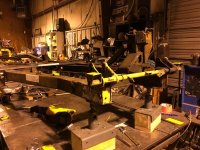
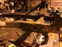
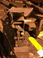
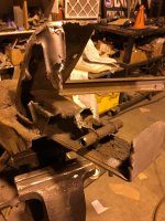
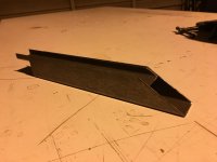
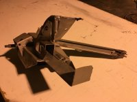
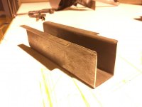
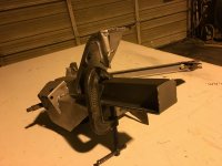
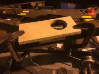
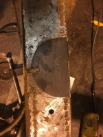
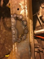
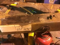
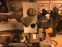
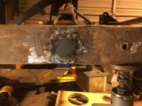
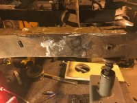
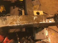
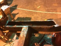
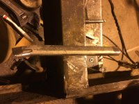
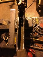
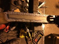
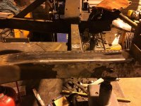
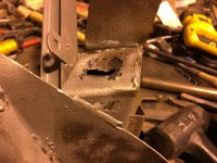
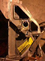
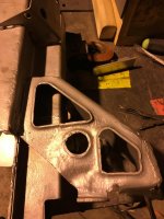
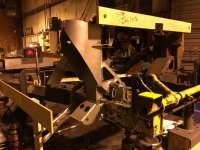
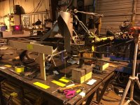
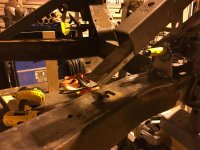
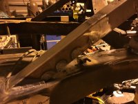
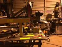
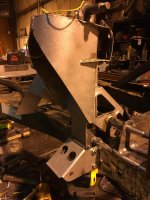
Hi John, I have 2 lasers that I will be using to setup the final alignment, tack welding, and final check before and after welding. I had forgotten about using a water level to check the floor. I have a very accurate 6 foot level I was planning on setting pads to measure off of to level and check the frame for twist. The water level will be a great way to make sure all the pads are shimmed to a perfect measuring surface. Last night I started removing the extra plates to get a feel for how hard this will be. Pretty easy to remove the plates so I am not worried about this repair. The top 18 inches of the top of the passenger frame rail will have to be replaced. Whoever did the welding built up areas with weld metal, in some places it is a pad 1/4 inch thick. They had no idea what they were doing. Thank you for the suggestion, that is great to have ideas that make the repair easier and better. Frank
 
OP
F

Frank Canale

Jedi Warrior
Silver
Country flag
Offline
Wow!!! What a great idea. I forgot to mention I have upper and lower fulcrum pins on order and should be here next week. I plan to get the frame ready for base measurements then replace the upper fulcrum pins and make fixtures to help get the passenger shock tower back in place after it is repaired before working on the driver side. One side at a time always working off the center line of the frame. Does this sound like a good approach? Frank
 
OP
F

Frank Canale

Jedi Warrior
Silver
Country flag
Offline
I have moved my frame to where I work and have it on one of our welding tables to check the dimensions with the service manual frame dimensions. The frame is perfectly square. The frame was twisted 1/4” +. After a lot of measuring the passenger back corner needed to be pushed up. I welded post under the frame to clamp the correct points and used a hydraulic jack to raise the back corner. This process was done several times till all points are correct except the front outriggers and they both are the same 1/32- 1/16 “ low. I am not going to risk throwing it off somewhere else to correct this. The front driver outriggers is 3/16” back from correct. The other outriggers are correct. The rear spring mounts are within 1/16” of each other. My concern is the front spring towers. The driver side is 1/4 “ forward of correct. The passenger side is 1/4” back of correct. The passenger side is going to be removed to repair the internal channel and bump stop mounts. When I put it back it will be mounted in the correct position. I have not decided about the driver side but I know it is off and will probably move it so that it is correct and all will be square. Probable would be easier to get a better frame but in the end I know this one will be right. Sorry for the long post, Frank
 

DavidApp

Yoda
Gold
Country flag
Offline
Detailed posts are great.

You are fortunate to be able to correct the frame. I am sure there are plenty around that are way off. I checked my frame was square and not twisted but did not verify the suspension towers.
While you have it in a convenient position you should try to remove the front leaf spring bolts. That is if you have not already done that.

David
 
OP
F

Frank Canale

Jedi Warrior
Silver
Country flag
Offline
Hi David, I have not removed the rear spring mounting pins. Do I need to remove them, They are in good shape?
The passenger spring tower has been removed.Tools to remove the tower were 4 1/2" cut off wheel in a grinder, dremel with heavy duty cut off wheels, Saws all with bi metal blade, and a die grinder with cone shaped burr. I will not lie, this part is difficult to remove. I could have done it easier butchering the fulcrum pins to make room for the grinder but wanted to see if it was possible to remove it and save the fulcrum pins and it is just takes longer. There is a hole in the side of the frame as well as the top.. The hole in the side is where the lower bump stop tube rusted away, and the top hole is at the bottom of the tower brace where it meets the frame. I plan to repair both holes as well as the top of the frame where all the extra welding has made a mess of the top of the frame. Replacing the top should make for a good foundation and easier to reposition the repaired spring tower. The third picture showed the inside of the spring tower with the lower bump stop tube gone and the damage the PO did to the section that the tubes go thru. That area should be a square shaped channel. The last picture shows the fulcrum pin removed. I removed the weld metal where it was cut apart previously. The pieces were not put back together with tight joints so it was easy to take it back apart with the dremel. I will be putting the pieces back together correctly around the new fulcrum pin as well as forming a new center channel and new lower bump stop tubes. Frank
 

Attachments

  • IMG_0242.jpg
    IMG_0242.jpg
    93.8 KB · Views: 109
  • IMG_0239.jpg
    IMG_0239.jpg
    82.2 KB · Views: 111
  • IMG_0241.jpg
    IMG_0241.jpg
    74.2 KB · Views: 111
  • IMG_0243.jpg
    IMG_0243.jpg
    76 KB · Views: 99

DavidApp

Yoda
Gold
Country flag
Offline
I am really glad I did not face that kind of issue. Not sure if I have the equipment or level of skills to fix that.

On the rear spring bolt.
If you ever had to replace the rear springs after you got the car back together those pins have to come out otherwise the body has to be lifted up a bit.
Now would be the time to do that. Penetrating oil and patience seems the way to go.

David
 
OP
F

Frank Canale

Jedi Warrior
Silver
Country flag
Offline
I took a look at the rear spring pins and sure enough they have been welded to the frame. I just had to walk away after seeing that. I worked on forming the pieces to make the spring tower diagonal brace. once i have the tower repaired and in place I can cut the brace and repair it. I plan to cut the outer part , and offset the inner part to help keep the brace straight and will also be stronger. I cut the damaged inner channel out. I then formed the inner channel notched and fitted it. This is the tower with the new channel clamped in place. Tomorrow I will work on repairing the holes in the frame and drill the holes for the lower bump stop mounting tubes. I have the tubing ordered but it has not arrived. That will not hold me up because the tower needs to be welded to the frame before the tubes are welded in. So far no surprises, just takes time to get it put back together correctly. Frank
 

Attachments

  • IMG_0247.jpg
    IMG_0247.jpg
    35.3 KB · Views: 82
  • IMG_0244.jpg
    IMG_0244.jpg
    40.8 KB · Views: 86
  • IMG_0246.jpg
    IMG_0246.jpg
    36.3 KB · Views: 89
  • IMG_0245 (1).jpg
    IMG_0245 (1).jpg
    49.2 KB · Views: 85

DavidApp

Yoda
Gold
Country flag
Offline
Sorry about that.
Welded to the frame as in PO taking a Welder to them or the normal rust weld?
If the latter penetrating oil and time often work to free them. The head on the inside of the frame are tapped for an extraction bolt.

David
 
OP
F

Frank Canale

Jedi Warrior
Silver
Country flag
Offline
Looked at it again and it is welded all the away around by PO. things like this just make me upset. Some people should not be allowed to own a welder.
 

CJD

Yoda
Country flag
Offline
The tower came off very cleanly. It almost looks like that may be the best way to replace the front pins...saving time in the long run.

Interesting that the prior thought it necessary to weld the spring pins in. Of course, you could leave them as-is, since it'll be another 20 years before the bushing will need to be replaced again...but I am sure you will decide to fix it now!?! It will probably be easiest to grind out the entire tubes and start over from scratch.


Enjoying watching the progress!
 

sp53

Yoda
Country flag
Offline
Looking good Frank on the frame rebuild. Honestly my welding is not that great; I do not have that kind of experience.

On those rear pins, I would suggest taking another look because they look welded around because the sleeve is welded around to the frame, but they are a pin in sleeve that gives that appearance. I have almost always had to heat those pins up just to make them move fuzz, so I doubt they came lose. Once when I pounded them crazy with 10 pound hammer, I got them out, but it was a big job of pounding, so go with the heat.
steve
 

DavidApp

Yoda
Gold
Country flag
Offline
If I had it to do again I would make sure they came out.

Pulling with the thread and I thought an air hammer may do more than a Big Hammer. The air hammer may work like an impact wrench looseness bolts. Plus some heat after a long soak with penetrating oil.

If all else fails it looks like you have the equipment and skills to replace the frame parts.

David
 
OP
F

Frank Canale

Jedi Warrior
Silver
Country flag
Offline
Thank you Steve, I did take another look and was able to take a scribe and clean what I think is the joint between the head of the pin and the sleeve it goes thru. For now soaking them. Today was devoted to repairing the holes in the frame and the top of the frame where the spring tower mounts. To cut the damaged area out I used a hole saw without the center bit. I took a piece of 3/4" plywood and drilled the hole with the center bit to make the jig to use the hole saw without the center bit. once the damage is removed I use the jig to scribe a piece of .063 ( 16 gauge ) sheetmetal and cut it out on the band saw. This piece is a perfect fit to be welded to the frame. Next was the side of the frame where the lower bump stop tube rusted away. The process was the same.
Then came the ugly top of the frame where all the cutting and welding had been done. Part of the inner flange had to be replaced. The replacement flange has a slight curve to it so I stretched the flange to match the curve. Then on to the top repair. I punched 3/16" holes on the inside for my spot welds. The welding process took little longer because I wanted to control the heat. Short welds and cooling the welds with compressed air takes a little longer but I did not want to warp the frame again. I also have the front of the frame pulled down on the screw jacks with light pressure with a cable come a long. After welding it does not take a lot to finish tig welds and also does not create a lot of heat. So far I am very happy with the repairs. It has taken a lot of time but I think it has been worth it. Tomorrow on to the tower repair and mounting it back on the frame. Frank
 

Attachments

  • IMG_0248.jpg
    IMG_0248.jpg
    55.4 KB · Views: 97
  • IMG_0250.jpg
    IMG_0250.jpg
    68.5 KB · Views: 93
  • IMG_0251.jpg
    IMG_0251.jpg
    72.3 KB · Views: 92
  • IMG_0255.jpg
    IMG_0255.jpg
    74.1 KB · Views: 90
  • IMG_0253.jpg
    IMG_0253.jpg
    78.2 KB · Views: 91
  • IMG_0254.jpg
    IMG_0254.jpg
    72 KB · Views: 88
  • IMG_0256.jpg
    IMG_0256.jpg
    65.4 KB · Views: 92
  • IMG_0257.jpg
    IMG_0257.jpg
    64.3 KB · Views: 86
  • IMG_0258.jpg
    IMG_0258.jpg
    67.6 KB · Views: 94
  • IMG_0259.jpg
    IMG_0259.jpg
    65.5 KB · Views: 91
  • IMG_0260.jpg
    IMG_0260.jpg
    75.7 KB · Views: 90
  • IMG_0261.jpg
    IMG_0261.jpg
    75.5 KB · Views: 82
  • IMG_0262.jpg
    IMG_0262.jpg
    77.5 KB · Views: 77

DavidApp

Yoda
Gold
Country flag
Offline
Great work there Frank.

We are fortunate here in the U.S. because I believe that frame repair is not allowed in some countries.

Keep soaking the pins.

David
 
OP
F

Frank Canale

Jedi Warrior
Silver
Country flag
Offline
Thank you to all for the support and suggestions. I know a little bit about metal and welding but I have a lot to learn about the British cars and you all are a huge benefit to my restoration.Today was spent tacking the pieces that were cut out of the spring tower by PO. I had to carefully grind the welds that held the piece to the fulcrum pin. Once it was off I tacked it back in place to the spring tower. Then the bulk of the day was spent shimming and clamping and measuring over and over till the tower is sitting on the frame fully supported. Once the tower was in the correct position I was able to measure the pieces that needed to be added to the bottom of the tower where it sits on the frame.tomorrow I have to drill for the bump stop tubes weld up repairs to the spring tower and then we will start welding the spring tower to the frame. Hopefull that tomorrow the passenger side will be done and then to the driver side. Not much worth taking pictures of today but tomorrow should be full of photos. One tip that i have been using and you might notice it in the picture when I am bead blasting parts or working with parts that I don't want threads damaged I will take a piece of electrical shrink tubing and put it over the threads and shrink it with a heat gun. The tubing is not that expensive and is very durable. Frank
 

Attachments

  • IMG_0263.jpg
    IMG_0263.jpg
    44.4 KB · Views: 86

sp53

Yoda
Country flag
Offline
Very nice quality looking wonderful, as the forum grows and the old cars get older with new challenges people are still fixing them--- amazing.
 
OP
F

Frank Canale

Jedi Warrior
Silver
Country flag
Offline
I did not get as far as I thought i would but happy with progress. I am not sure what the box that is attaches to the spring tower is for but it must hold water because both sides are rusted in the bottom and on the side. before and after shots. where the fulcrum pin was cut out by the PO I tacked the pieces back in place then used the tower to check the measurements for the fulcrum pin. After confirming the measurements I took the tower back off and finished welding the pieces in place. All of the welds were also welded inside but the inside weld were not finished like the outside. After that, back on the frame to plot the lower bump stop tubes. The lower tube went well, the upper hole I totally missed but caught it before the final size bit. punch a couple of slugs to fill the hole. Now I know where the center of the hole goes so the holes are done . Cut the tubing and reamed the center to 21/32 so there is just a slight clearance for the 5/16" bolts. The tubes will be welded in after the tower is welded to the frame. They are in the way of a couple of welds so that will have to wait. Reset the tower on the frame. Initial check showed that everything is lining up very well. Tomorrow I will reset the frame to points on the table and recheck every measurement one last time before tacking and welding the spring tower.
 

Attachments

  • IMG_0264.jpg
    IMG_0264.jpg
    76.5 KB · Views: 81
  • IMG_0267.jpg
    IMG_0267.jpg
    76.9 KB · Views: 85
  • IMG_0265.jpg
    IMG_0265.jpg
    78.1 KB · Views: 83
  • IMG_0266.jpg
    IMG_0266.jpg
    68.7 KB · Views: 86
  • IMG_0268.jpg
    IMG_0268.jpg
    78.1 KB · Views: 81
OP
F

Frank Canale

Jedi Warrior
Silver
Country flag
Offline
Thank you John for solving that mystery. My car did not have bump stops on it so I did not know. The passenger spring tower is back on the frame and welded up. I feel sorry for whoever has to take it apart the next time, hope it's not me. The first picture is the tower clamped in place. I used turnbuckles to hold the tower where I needed it. The turnbuckles make for easy fine adjustments. The top of the tower was pulled a little bit forward and toward the center to offset the shrinkage of the welds. After the welds cooled the turnbuckles were loosened and that is exactly what happened, the tower pulled to the outside and to the rear. I got ahead of myself and forgot to repair the diagonal brace before welding. This made for a little concern but was able to re pull the tower and get the brace repaired and back in position. The diagonal brace is made up of two channels welded to form a tube. I cut the brace in two different places to keep it straight and make it as strong as before. I missed taking a photo of the inner channel before I welded the outer . This is what it looks like after it was finished. Once everything was welded this showed the vertical alignment. There is a jig that centers the string in the 3/4" hole in the top of the spring tower. The laser shows the vertical alignment as well as the correct position front to back. There is a board that slides over the front outrigger that is cut to the correct dimension from the service manual. There was not anything to show for the alignment from the front because all of that is done by measuring from the centerline.There are numerous pieces of tape on the table with frame location points, measurements, calculations because the drawing references center points and that is hard to measure with a tape measure so I calculate to the outside of piece being measured so that it is easy to push the tape to the outside and use the new measurement . Last picture for the night shows the tower welded up and the lower bump stop bracket in place. So far the alignment is very good plus or minus 1/32 except for the fulcrum pin that is dead on height and parallel to the center line. Next is the driver side that should be easier because there is no frame damage on the side and the only damage to the tower is the bump stop water box and where the PO cut the fulcrum pin out.
 

Attachments

  • IMG_0269.jpg
    IMG_0269.jpg
    99.7 KB · Views: 80
  • IMG_0270.jpg
    IMG_0270.jpg
    63.6 KB · Views: 78
  • IMG_0272.jpg
    IMG_0272.jpg
    63 KB · Views: 79
  • IMG_0271.jpg
    IMG_0271.jpg
    87.3 KB · Views: 82
  • IMG_0273.jpg
    IMG_0273.jpg
    70.1 KB · Views: 81
Similar threads
Thread starter Title Forum Replies Date
W For Sale 1960 TR3A for sale Triumph Classifieds 0
G For Sale 1960 TR3A for sale $11,999 Triumph Classifieds 0
W TR2/3/3A 1960 TR3A Radiator replacement recommendations Triumph 11
M TR2/3/3A 1960 TR3A--intake manifold-to-SUH6 carbs studs Triumph 3
M TR2/3/3A 1960 TR3A turn signal harness Triumph 6
A TR2/3/3A 1960 TR3A front brake dust covers Triumph 5
F Wanted 1960 Triumph TR3A fuel tank Triumph Classifieds 5
Tinkerman TR2/3/3A Hood stick assembly 1960 tr3a Triumph 7
Tinkerman TR2/3/3A 1960 TR3A engine compression question. Triumph 7
Tinkerman TR2/3/3A Rebuilding SU carbs 1960 TR3A Triumph 3
Tinkerman TR2/3/3A 1960 TR3A post 60000. WON"T START ???????????????? Triumph 8
Tinkerman TR2/3/3A 1960 TR3A Boot rubber seal installation? Triumph 7
Tinkerman TR2/3/3A 1960 tr3a sheet metal fitment Triumph 6
Tinkerman TR2/3/3A 1960 TR3A carpet installation Triumph 5
Tinkerman TR2/3/3A 1960 TR3A Tonneau Capping Installation Triumph 1
Tinkerman TR2/3/3A 1960 TR3A Tonneau Trim Mill board Triumph 10
M_Pied_Lourd TR2/3/3A 1960 Triumph TR3A Trunk Seal Orientation Triumph 6
Tinkerman TR2/3/3A Prepping the grill for installation for my 1960 TR3A Triumph 1
Tinkerman TR2/3/3A Sealing fender to body 1960 TR3A Triumph 15
Tinkerman TR2/3/3A Windscreen mounting tips 1960 TR3A Triumph 2
Tinkerman TR2/3/3A 1960 TR3A Bottom Rubber Seal on the Windscreen Triumph 3
Tinkerman TR2/3/3A Tunnel installation question 1960 TR3A Triumph 11
Tinkerman TR2/3/3A Another Freeby from the past. For a 1960 TR3A Gas Tank Triumph 4
Tinkerman TR2/3/3A 1960 TR3A Holes in the tranny tunnel Triumph 11
Tinkerman TR2/3/3A Carpet underlayment, TR3A 1960 Triumph 10
Tinkerman TR2/3/3A Major oil leak from original oil filter system 1960 TR3A post 600000 series Triumph 3
D TR2/3/3A 1960 TR3a front suspension Triumph 2
Tinkerman TR2/3/3A Front windscreen help needed. TR3A 1960 Triumph 9
D TR2/3/3A fitting windshield/frame to 1960 Tr3a & Brooklands screen removal Triumph 2
Tinkerman TR2/3/3A TR3A 1960 Gas on three out of four plugs ? Triumph 6
Tinkerman TR2/3/3A 1960 TR3A post 60,000 series seat pan covering Triumph 3
Tinkerman TR2/3/3A 1960 TR3A seat tack strips Triumph 1
Got_All_4 TR2/3/3A Finish on a 1960 TR3A Fluid reservoir? Triumph 6
60TR3A TR2/3/3A 1960 TR3A Small Mouth [Huh?] on eBay Triumph 63
M_Pied_Lourd TR2/3/3A 1960 TR3A Mystery G Triumph 24
Tinkerman TR2/3/3A 1960 TR3A Instrument Cluster Ground Post Screw Triumph 9
M_Pied_Lourd TR2/3/3A Restoration of TS 69891LO 1960 TR3A Triumph 36
T TR2/3/3A 1960 TR3A oil leak issue [imagine that!] Triumph 5
T TR2/3/3A 1960 TR3A engine compartment color Triumph 8
PAUL161 TR2/3/3A Colonal Tom Parkers 1960 TR3a For Sale! Triumph 3
T TR2/3/3A 1960 TR3A now with rack and pinion Triumph 22
Tinkerman TR2/3/3A Bulkhead Sealer Plate TR3A 1960 Triumph 3
D TR2/3/3A 1960 TR3A Paint Question Triumph 24
gubba TR4/4A 1960 TR3A with tr4 motor and tranny? Triumph 22
D TR2/3/3A 1960 TR3A Flasher Triumph 7
R For Sale 1960 Healey BN7 Oil Pan For Sale Austin Healey Classifieds 0
J Wanted Hood (Bonnet) for a 1960 BT7 Austin Healey Classifieds 0
G For Sale 1960 TR3 A Triumph Classifieds 0
dougie 1960 Austin Healey 3000 Works Lightweight vs. 1962 Ferrari GTO Austin Healey 6
G For Sale 1960 BugEye..Very Good..$20,500 Austin Healey Classifieds 0

Similar threads

Top