 Hey there Guest!

 but were afraid to ask:
  STOP!! Never post your email address in open forums. Bots can "harvest" your email! If you must share your email use a Private Message or use the
  smilie in place of the real @
 Pretty Please - add it to our Events forum(s) and add to the calendar! >>
CraigLandrum
Jedi Hopeful
Offline
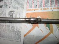
After disassembling, cleaning, and buzzing out the turn signal and horn contacts in our steering control head for our barn-find TR3A, we puzzled over how the control head mounted onto the shaft so that the control head would stay static while the wheel turns (to allow the turn signal to reset after the turn). We know about and have the three set screws that attach the head to the wheel. After perusing the TR3 maintenance manual we realized that we we are apparently missing the stator tube, which runs down the middle of the shaft and emerges at the bottom of the steering control box at the front of the car, held in place with a compressor nut (we have the brass bushing and compressor nut). The small shaft that is part of the control head itself just fit into the top of the steering column shaft, so we suspect that the missing stator tube will need to be a tight press fit inside the control head shaft, but large enough to allow the wires to go through, and long enough to extend all the way through the steering control box in a single piece, in order to hold the turn signal part of the control head in the 12 o'clock position.
Couldn't find any specs, but it appears that this tube would be about 3/8 inch outside diameter with a thin wall, and would need to extend from the steering wheel all the way down through the control box.
This part is marked N/A in every catalog we could find. Does anyone have the exact specs for this tube (diameter, length), assuming it is for a non-adjustable standard TR3A steering column? I suspect I might be able to pick this up at a hardware store somewhere. Any tips appreciated.
By the way, disassembling and cleaning a TR3 control head is an exercise in frustration, and it involved simultaneously positioning the turn signal arm, a spring-held contact plate that is a slip fit on the arm, a spring loaded brass slotted piston with a teensy roller wheel, and a curved 180 degree rod holding two *more* compressed springs that help return the signal arm to its proper position. Oh, yeah, almost forgot the two spring-loaded cams that must also be correctly positioned in slots as you are trying to hold the other four springs in position - all while trying to insert the small brass bolt, lock washer, and brass nut that holds it all together. We finally got it assembled correctly after our fourth attempt, and the the turn signals buzzed out on the meter and the signal arm correctly resets to the center position after a simulated turn. Then we had to figure out the non-intuitive horn wiring which is held on with another two brass screws, etc, etc. If anyone ever needs to take one of these things apart to fix or repair, ask us first - we can offer some good advice gained through painful experience


 A friendly reminder - be careful what links you click on here. If a link is posted by someone you don't know, or the URL looks fishy, DON'T CLICK. Spammers sometimes post links that lead to sites that can infect your computer, so be mindful what you click.