• Hey there Guest!
    If you enjoy BCF and find our forum a useful resource, if you appreciate not having ads pop up all over the place and you want to ensure we can stay online - Please consider supporting with an "optional" low-cost annual subscription.
    **Upgrade Now**
    (PS: Subscribers don't see this UGLY banner)
Tips
Tips

TR2/3/3A TR3A fuel gauge question

CJD

Yoda
Country flag
Offline
I'd rather adjust the sender than the gauge if that is possible with this TRF sender.
Regards,
Bob

Excellent choice! The sender is very straight forward, and the gage is more work. Plus, if the sender can't be adjusted in range, you are all ready to install one that will work.
 

dklawson

Yoda
Offline
Bob, you can tweak the sending unit prior to installation in the tank as long as it is a question of re-adjusting the stop tabs. When you are ready to do this, just remember that the sender must have a ground connection to the car as well as having the green/black wire attached.

If you visit the link below and click on the "Old Fuel Gauge" link you can see a document I put together for another Mini owner friend. The document has pictures of the sending unit and some of the bench wiring. It may be of some help.
https://sites.google.com/site/purlawson/home/files
 

alanjohnturner

Jedi Trainee
Offline
You probably have a sender intended to run with a 10V stabilser like there is on a 4A/6. Because there is less volts the sender has a lower resistance so as to put the same current through the gauge.

Maybe adding a 10V stabilser will fix it. They are cheaply available.
 

dklawson

Yoda
Offline
As was hinted at above, the later senders that work with the voltage stabilizer have a wider resistance range and they change in the opposite direction (early senders w/o stabilizer decreases in resistance as the tank empties... later senders with the stabilizer increase in resistance as the tank empties). It is pretty obvious when you mix the gauge/sender components as the gauge needle goes the "wrong" way when you mix new and old.
 

alanjohnturner

Jedi Trainee
Offline
A 4/4A/6 gauges works by heat. Higher current means more heat and more deflection of the needle. This also means that they are not sensitive to the direction of the current.

Do the earlier gauges work on a different method?
 

dklawson

Yoda
Offline
It is not a question of direction of the current that makes early and late sending units work differently. The early and late gauge systems are totally different and you cannot mix early and late components.

The early gauges (that did not use the voltage stabilizer) are electromagnetic. A series of magent coils inside the gauge pull against steel attached to the gauge needle. From the front you can typically identify early gauges by their very thin needles that will flop all over the place as you manipulate the gauge. On the rear of an early gauge you will find two electrical terminals and two nuts attached to studs that pass through slots. The terminals on the back will be marked by "T" for "tank" and "B" for "battery". Apply power to the gauge and the needle instantly jumps from rest to where it is supposed to be. They are not polarity sensitive but the wires do have to be connected to the right terminals.

Compare that to the later gauges and you will see that the later needles are thicker/wider and they vibrate but won't bounce all over the place when you manipulate the gauge. The back of the gauge will only have two terminals without marking and there will either be two open holes with "screwdriver" slots behind them... or two cork disks covering those holes. Those are the gauges you mention that work by heat. Inside there is resistance wire wrapped around a bimetallic strip attached via a linkage to the needle. As the sending unit moves towards empty its resistance increases and that in turn reduces the current flowing through the gauge. Less current means less heating which means the bimetallic strip relaxes and the needle moves towards empty. As you mentioned, the later gauges work by resistance heating so they are neither polarity or connection sensitive. The two wires can be hooked to eithter terminal on the gauge. However, they are voltage sensitive and require the voltage stabilzer to drop the cars 14V (running) voltage down to a target 10V.

If you use a later sender with an early gauge, the needle will still move quickly as intended but it will move in the "wrong" directly... moving towards full as the tank empties. Likewise, if you use an early sender with a later gauge, that gauge will also show the same behavior but it will also NEVER show empty as the resistance range of the early sender is about 1/3 that of the later sender. Since the resistance range AND direction are different between the early and late senders, you cannot mix the gauge components as the gauge will be both innacurate and operate in the wrong direction.
 

TR3driver

Great Pumpkin - R.I.P
Offline
The gauge is easy enough to take apart, and cleaning sure won't hurt it none.
But be careful not to damage the fine wires inside the case.

I would just go ahead and tackle the calibration process. My guess is that some previous mechanic has loosened one of the adjustment nuts and didn't get it back in the right place.

As an alternative to running extension leads to the car, you can measure the sender resistance at empty, half and full; then use resistors to simulate those values on the bench. My local electronics store (not Radio Shack) sells an "assortment" of 5% tolerance leaded resistors with 5 examples of very value from 0.1 ohm to 100 Mohm for less than $10. And of course you can stack them up to get the value you want. IIRC, the later pages of Barney's (MGAGuru) article outlined the process; although you certainly don't need to build a box with the resistors.
 

dklawson

Yoda
Offline
You are right. Barney's web site includes a quick DIY method using resistors attached directly to the back of the gauge w/o making a fancy calibration box. It does work well.

However, the OP did say that he measured the "full" resistance of the sender with the arm "up" in the mid-60 Ohm range which is a bit low. Calibrating the gauge should still be possible but you would be compensating for a sender that only seems to have 2/3 of the intended range.
 
OP
T

TuffTR250

Jedi Warrior
Country flag
Offline
Here are my latest findings on the Roadster Factory fuel tank sending unit I put in my TR3A.
I took the sending unit out of the tank and hooked the wires back up and held it near the gauge so I could see the Ohm meter as well as the gas gauge.
1) I noticed that the TRF sending unit float arm is 2 inches shorter than the original sending unit. When the TRF sender is full down, it is 10-1/2 inches from the bottom of the sender cap As a result, the TRF sender shows empty when I still have between 1/8 and ¼ tank of gas. I’m sure this also affects the gas gauge readings overall., except maybe when the tank is TOTALLY full.
2) The TRF sending unit has the name Frekans and the numbers 0 90. I assume the numbers are the ohm ratings for the sending unit. Note: I have attached a picture of the TRF sending unit. As part of the plastic base unit of the sender it has plastic stop at the top and a stop at the bottom.
3) While out of the gas tank with no wires attached., I measured the resistance of the TRF sending unit. At the bottom stop it measured 3.1 ohms. At the top stop it measured 100.1 ohms. So it is working. correctly.
4) With the sending unit out of the tank and with the wires hooked up and the sending unit float arm at the top stop, my gas gauge showed right at 7/8 full. I then put the float arm in the middle of the sending unit range and at 48/49 ohms expecting the fuel gauge to show ½ tank of gas, but the gauge only read ¼ full. Maybe the range is not linear.
Regards,
Bob
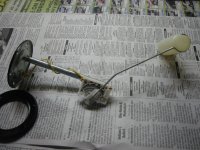
IMG_5132.jpg
 

martx-5

Yoda
Country flag
Offline
AHA!! Somebody else got stung with that bogus fuel sender. I bought one from Moss that was the same as the one you are showing. Here's a thread that I wrote up about that same sender, how it compares to the original, and finally the one that I bought form ebay that has worked fine...after a slight modification.

https://www.britishcarforum.com/bcf...3-Fuel-Sender-From-Moss&highlight=fuel+sender


Send it back to TRF. I told Shawn at Moss about the problem awhile back referring him to my thread, but I don't know if they've sourced a correct sender. Ebay will probably be your best bet.

Edit: Here's the guy from ebay...very reliable. Has almost 30,000 sales (over 4k in the last year) with 100% positive feedback.

https://www.ebay.com/itm/Triumph-TR...es&fits=Model:TR3&hash=item2eb67ca80b&vxp=mtr
 

dklawson

Yoda
Offline
The float arm length is troubling. That is more important than some of the resistance measurements you made.

For future reference, you cannot measure the sending unit resistance with the wires attached to it. The readings you get will have no meaning because the values you observe are influenced heavily by the resistance of the gauge (since it is connected).

It sounds like your choice is as Art suggested, return and replace. If you don't want to send the new unit back, you could cut the arm off your old sender and splice it onto the new one to get back to the proper length. However, joining the arms may be a tricky weld if you don't have a spot or a TIG welder.
 
OP
T

TuffTR250

Jedi Warrior
Country flag
Offline
A few questions:
1) On my old old sending unit the arm would not move since the unit is very rusty. I sprayed it with PB Blaster and that loosened it up a little. Is it possible to remove the arm from the metal container to get it to move freely?
2) The wire inside the cap to the coil is broken loose. Is it possible to repair that?
3) Is there anyone that repairs these sending units at a reasonable price?
Regards,
Bob
 

dklawson

Yoda
Offline
1) Not easily. Assuming the TR3 sender is like that on my Mini, the arm has some parts staked onto it under that cover. You can remove the cover with the arm complete but I am not sure about actually separating the arm from the cover. I think I posted this link earlier but I will repeat it:
https://www.sites.google.com/site/purlawson/home/files
Open the file labeled "OldFuelGauge.PDF"
It will give you an idea what is going on inside the sending unit.
2) Maybe. If you are talking about the resistance wire being broken, that can sometimes be fixed but it is difficult. It does not solder well (even with acid flux) and is therefore often secured to terminals with crimps. If you are talking about one of the copper wires connecting the resistance coil to the terminals, those are typically copper and can be repaired more easily.
3) I don't know of a firm that repairs sending units. However, it might be worth making some phone calls to ask. For us in NC, that would start with a call to Nichols Speedometer over towards Greensboro as they work on Smiths equipment. After that you would add to your list all the firms discussed whenever gauge rebuilding is mentioned: Nisonger, Mo Ma, Palo Alto Speedometer, APT (gaugeguys.com). I am sure there are others.

Regardless, I assume you know the drill. Never throw anything out. That damaged sender may have some life in it yet for someone.
 

interfx

Freshman Member
Offline
OK, I'm a newbie but here's what I have going on with my T3a.

1. Fuel gage used to work, until recently (until I started trying to remove the fiberboard glove box)
2. On the back of the fuel gage, have both top screw terminals wired (one green/black, other green). Lower terminals no wires connected. In fact, nuts not even loose that a wire might have been connected.

Question:
- How could this gage worked? I've seen the fuel gage show 1/2 tank, 1/4 tank etc.
- What do I need to do to get it to work? from the MG example shown, looks like I need a wire to the B terminal? (even though it looks like nothing (recently) was connected to it?

Suggestions?
 

TR3driver

Great Pumpkin - R.I.P
Offline
Normally there are only two wires and two terminals. There are two nuts just below the electrical terminals, which are adjustments (and should never be touched unless you have the unit apart so you can support the coils in the adjusted position while retightening the nuts). Then there is a mounting stud in the center of the back.

The factory relied on the mounting strap to provide a ground through its contact with the back of the panel. This is a common problem spot in my experience, so I recommend adding a short ground wire, with a ring terminal to fit over the mounting stud and running over to the ground tie point on the back of the instrument panel.

You can see one end of it in this photo


PS, if you have loosened the adjustment nuts, the gauge may no longer work at all. At that point, while you can try loosening the nuts just slightly and tapping them along the adjustment slot; most likely the pole pieces have rotated and the only way to fix the gauge will be to remove the bezel, glass and face (which will require carefully bending the needle) for access to the pole pieces. There is a very good writeup at https://mgaguru.com/mgtech/electric/fg_01.htm (although being for an MGA, the resistance values are slightly off for a TR3).
 

interfx

Freshman Member
Offline
Thanks Randall, here's what I tried...

1. Adjustment nut - I did not touch, or adjust
2. Added a ground wire from mounting stud (center)/nut to dashboard stud/nut.

Still have no response from the fuel gage... Any other things I should try?
 

TR3driver

Great Pumpkin - R.I.P
Offline
My next step would be to check with a test lamp or meter that you are getting power on the green wire. If not, the fuse might be bad (or not making good contact with the fuse block). Just because I subscribe to the "A test is worth a thousand theories" idea, I would probably check again at the green wire on the fuse block.

A good next step might be to look in the tank (through the filler) and see if perhaps the sender float has sunken or is no longer on the arm.

If that looks good, I might try disconnecting the green/black wire, and applying power to the green terminal (and ground) to see what happens. The gauge should go past full; if not then there is a problem with the gauge. If it does go past full, I'd start looking for a short in the wire to the tank.
 
Similar threads
Thread starter Title Forum Replies Date
T Wanted Working Fuel Gauge for TR3A Triumph Classifieds 5
T TR2/3/3A TR3A Fuel Gauge problem Triumph 10
K TR2/3/3A Can a TR4A Fuel Gauge be swapped into a TR3A? Triumph 8
D Wanted TR3A Fuel gauge Triumph Classifieds 4
B TR2/3/3A Fuel gauge issue 60 TR3A Triumph 13
tmc TR2/3/3A TR3A fuel gauge Triumph 5
TR3TR6 TR2/3/3A TR3A FUEL GAUGE Triumph 8
NutmegCT TR2/3/3A fuel gauge / sender TR3A Triumph 25
NutmegCT TR2/3/3A Fuel gauge fixed! TR3A Triumph 7
NutmegCT TR2/3/3A Fuel gauge needle replacement TR3A Triumph 0
C TR2/3/3A TR3A Fuel Gauge Triumph 1
Q TR2/3/3A 61 TR3A Fuel Pump Triumph 4
Donald1107 59 TR3A Fuel Pump Triumph 48
F Wanted 1960 Triumph TR3A fuel tank Triumph Classifieds 5
T TR2/3/3A Late Fuel Tank in Pre-TS60000 TR3A Triumph 3
G TR2/3/3A TR3A Electrical Quirks, Flasher, Wipers and Fuel Guage Triumph 4
T TR2/3/3A Is there a special way to get fuel pump off and on a 1961 TR3A? Triumph 4
PatGalvin TR2/3/3A New Fuel Lines TR3A Triumph 2
Anthony_S TR2/3/3A Fuel pump and who knows what else TR3a Triumph 23
R TR2/3/3A TR3A fuel line Triumph 2
R TR2/3/3A TR3A Fuel sending unit Triumph 3
JohnnyMead TR2/3/3A TR3A Routing Fuel Line: Fuel Pump to Carbs Triumph 15
Bremer TR2/3/3A TR3A fuel pump questions Triumph 15
angelfj1 TR2/3/3A TR3A - Fuel Tank Banjo Bolt Triumph 6
bigjones TR2/3/3A TR3A fuel line Triumph 13
JohnnyMead TR2/3/3A TR3A Fuel Tank-Fuel Line Question Triumph 8
ekamm TR2/3/3A Boot closeout for fuel tank tr3a Triumph 13
angelfj1 TR2/3/3A TR3A - Fuel Tank/Boot Fiberboad Panel Triumph 8
M TR2/3/3A TR3A Fuel Pump Refurbish Triumph 20
angelfj1 TR2/3/3A AC Fuel Pump for TR3A Triumph 6
Geo Hahn TR2/3/3A TR3A Fuel Sending Unit Triumph 1
trglory TR2/3/3A TR3a spark plugs Triumph 1
P For Sale 61 TR3A Triumph Classifieds 1
D TR2/3/3A 59 TR3A Gearbox lever will not move. Triumph 11
71TR6 TR2/3/3A TR3A Front Bumper Mount Triumph 11
mctriumph For Sale Project car 61 Tr3a Triumph Classifieds 0
71TR6 For Sale TR3A Nose Triumph Classifieds 0
71TR6 TR2/3/3A A TR3A wiring question Triumph 17
P TR2/3/3A 1958 TR3A missing on cyls 2 & 3 Triumph 8
mctriumph For Sale scrapping two 59 Tr3a's Triumph Classifieds 15
J TR2/3/3A TR3A Finally on the Road! Triumph 6
angelfj1 TR2/3/3A TR3A Boot Millboard Install Triumph 7
G TR2/3/3A TS37903F Is my engine a TR3A engine because my starter says no. Triumph 3
B TR2/3/3A TR3A Gearbox fluid capacity question Triumph 7
Hamish Racing TR2/3/3A Harewood hill climb Yorkshire TR3a Triumph 3
Hamish Racing Harewood Hill Climb Yorkshire TR3a Racing 0
J TR2/3/3A 58 TR3A Coil weak? 9KΩ on the secondary with a 1968 HA12 45208A non-ballasted coil. Triumph 4
J TR2/3/3A 58 TR3A Coil weak? 9KΩ on the secondary with a 1968 HA12 45208A non-ballasted coil. Triumph 1
T TR2/3/3A Looking for a TR3A front bumper Triumph 6
Hamish Racing General TR TR3a hillclimb Thumdrrstorm video uk Triumph 4

Similar threads

Top