• The Roadster Factory Recovery Fund - Friends, as you may have heard, The Roadster Factory, a respected British Car Parts business in PA, suffered a total loss in a fire on Christmas Day. Read about it, discuss or ask questions >> HERE. The Triumph Register of America is sponsoring a fund raiser to help TRF get back on their feet. If you can help, vist >> their GoFundMe page.
  • Hey there Guest!
    If you enjoy BCF and find our forum a useful resource, if you appreciate not having ads pop up all over the place and you want to ensure we can stay online - Please consider supporting with an "optional" low-cost annual subscription.
    **Upgrade Now**
    (PS: Subscribers don't see this UGLY banner)
Tips
Tips

General TR Instrument Faces

OP
CJD

CJD

Yoda
Country flag
Offline
Thanks, JP...I hope this thread pops to multi page soon...real pain scrolling all the way down!

I was ready to paint this weekend, but I am having second thoughts on my paint selection for the markings. The weather was good enough to excercise the TR3 yesterday, so I had chance to get a very close look at decent instruments in the sunlight. The TR3 has a very beautiful paint for the markings that appears pearlescent in the sunlight. I am certain that I would be the only one able to notice the difference from the bright Krylon white...but it bugs me that it would not be perfect.

I have to Google paint some more...or learn to let go of my OCD tendency!?

Later edit...

I give up. If there is a pearlescent white out there, I am unable to track it down. Bright white it will be. I will be painting the tach face as soon as I finish the windscreen stanchions to get my table cleared...
 
Last edited:

sp53

Yoda
Country flag
Offline
Wow John how could I add anything? “To boldly go where noman has gone before.” Anyways I rebuilt my gauges, but never consideredrepainting the faces plus I left the amp gauge sealed up because I could not getthe glass face off. The women from Moma said she would silk screen the facesfor me, but also suggested I take a very soft dry paint brush and wipe the dustand dirt off plus I think they sold the company since I last talked to her. I thinkit was her and her son who did the work. One thing I did learn the hard way wasthat the old grease on the odometer becomes like tar and will tear itself up ifleft on. Looks great John keep it up
 
OP
CJD

CJD

Yoda
Country flag
Offline
First try on the actual face...went some good and some bad. I will have to sand it down and retry later. The main issue is the base paint was laid down 2 weeks ago, so the marking paint did not bond as well as it did on the trial pizza pan. The pizza pan was all sprayed within 3 days, so I cannot scrape the markings off. The base was still soft enough to allow a bond. On the face, the base paint hardened to much, so the bond is not so good. The result is close, but no cigar.

Here is a photo album of the process:


This is the face wrapped in blue vinyl mask


The laser at work.


This is the finished cut. The next step was to carefully peel the rev limit mark to spray it. Then the rev limit line was masked and the rest of the markings were opened with a #11 exacto blade to ready for the white.


I know you are probably thinking it looks the same...but without the bad focus there are small rough edges from the marking paint lifting with the vinyl removal. The solution...

I have to base and mark all in one weekend. No problem...it'll get there...
 

Tr3aguy

Jedi Knight
Country flag
Offline
How much to do mine when i get to that point......I think I know your address?? Seriously it looks great to me.....FYI by fall I should have a little more garage space.....gainfully employed again:smile:
 
OP
CJD

CJD

Yoda
Country flag
Offline
Thanks, Doug. JP, I'd be happy to do yours once I get the magic formulae going. Glad to hear about the new job...although I was hoping we'd get you down here! Same location, or are you moving again?
 

DNK

Great Pumpkin
Country flag
Offline
Bro lives in Aldie.
There frequently
Bought my Lotus Cortina in the Vienna area in 76
 
OP
CJD

CJD

Yoda
Country flag
Offline
Well, after 2 weeks down with a nasty variety of the flu, I'm back to work. I have completed the Tach. Everything was moving ahead well, till I had a set back in the calibration phase...

To calibrate the mechanical tach/speedo, you have to adjust the amount of magnetism there is in the spinning internal steel wheel. To do that, I bought a very strong magnet. Let me rephrase that...a VERY STRONG MAGNET!! I went online and ordered the strongest rare earth magnet I could get for $30, including shipping. Here is what came in the package:


If you look closely, you will see that there is about 12 inches of packaging bubble wrap, with the new magnet in the center. Even with this much packing, the magnet still was able to pick up all the steel screws I had out on the work table. This is no ordinary magnet!! This should have been an omen...I'm slow to catch on, though. Here is the magnet unwrapped:


It is 1" x 2" x 2". The pulling power is listed as 85 pounds...but I think that was a conservative measurement. I will get into the calibration later, but the bottom line is I got the magnet too close to my new instrument face...and yep...it crashed into the fresh face. It smashed the face, my fingers, the flimsy needle, and worst of all, it broke the needle stop off.

Bummer!

The face is steel, and the needle stop is a brass pin. Mine broke off flat with the face. I had to start over, from less than scratch. Here is the pin drill I used to remove the stub of the old pin:


Of course, I had to remove the paint around the hole, and used some spring steel for the new peg:


Then I silver soldered the new peg to the face plate. After a quick attempt to sand the face smooth...it was obvious I had to blast it and start from scratch. Did I mention...Bummer?
 
OP
CJD

CJD

Yoda
Country flag
Offline
So, here is a quick pictorial of how to reface an instrument. First, the sand blasting down to bare metal. I tried several other metal prepping, but it became clear that the only way to ensure the paint would not peal is to use sand. The resulting surface is very rough, so the paint will never peal. Here is the new peg after silver soldering:


After blasting the old face and back, I primed with PPG DPL90 epoxy primer. Once the primer hardened, I sanded with 220 grit paper and top coated with Krylon semi-gloss. Then the masking, laser cutting...and 24 hours from the "incident" with the magnet, I was back to calibrating:


OP
CJD

CJD

Yoda
Country flag
Offline
Now, the face is done, so I am finally back to the mechanicals. For those that follow, always start with the tach. The mechanicals are identical to the speedo, but you don't have the added complication of the odometers to get in the way. The tach is a great warm-up for the speedo. Dissassembly is pretty easy, and is the opposite of the following pics of the reassembly. The reason you HAVE to dissassemble the unit is that the old grease turns to glue after about 10 years. This old sludge is what strips the odometer gears...so always take everything apart and clean the old grease off.


The first step in reassembly is putting the magnetic spinner back in the housing. Here are those 2 parts:


Trial fit the two parts, using fresh grease. Make sure the spinner turns freely, with absolutely no binding:


Now, remove the spinner, and slip the eccentric lock retainer onto the spinner shaft. Then re-install the spinner and retainer.


Do not over tighten any of these tiny screws.
 
OP
CJD

CJD

Yoda
Country flag
Offline
Now the dial housing goes on. This is a pic of the clock spring, which is extremely fragile. If it is broken, you need a new assembly. I never give up, but this is one part I would personally make no attempt to repair. While the dial housing is off, even lifting the assembly without supporting the aluminum disc will irrepairably stretch the clock spring. Do not attempt any cleaning stronger than dusting with a soft paint brush...it's just not worth the risk.


This is the orientation that the dial housing goes onto the main frame assembly:


It is best to either not lubricate, or use a lubricant that you know will not turn gummy over time. I used LPS #1, and then gently air blew the excess off:


This is the housing back on the frame. There is a needle on the back of the housing dial that fits inside a tiny, tiny brass bearing within the spinner. Make sure this pin is not bent, and that it slips gently into the spinner. Four tiny screws lock it down...again, no muscle on these screws:


Once in place, there is an adjustment screw on top of the housing. This screw adjusts the amount of play in the needle bearings. You want to adjust it so you can still feel end play, but only just. Better to have it too loose than too tight!!!


And...the face and needle go on. I have it set in the case, but do not mount in the case if you plan to do a calibration. And that is the point of this excercise anyway!


Notice that I first set the needle so it aligns with the little dot on the face. This will get you close to the idle calibration. I then gently popped the needle over the stop, and pressed it gently down onto the needle shaft. Do not press firmly yet...you will have to adjust it later.

Of note: here is the paint that is sold online to refresh the needle reflectivity. I tested it alongside the Krylon flat white spray paint, and I cannot tell a significant difference. I went with the Krylon, even though I had the special paint...plus, brushing this paint sucks. Spraying is always more uniform.


I am now ready to calibrate. I have to take the wife to lunch....will pick up later today.
 

dklawson

Yoda
Offline
Great work on the gauge faces and I am very sorry about the damage from the killer magnet. Those big magnets are dangerously strong. It's all too easy to get your finger stuck between one and someplace you wish it wasn't. I've gotten a couple of blood blisters from those things.

For the future reference of those reading this thread, Google for the 27 page PDF document "Repairing Jaeger and Smiths Speedometers" by Anthony Rhodes. It is a must-read reference to have at hand whenever working on speedometers and tachs.

John, there is an alternative to trying to re-magnetize the entire tachometer/speedometer. If the gauge reads too high (gernally unlikely) then you can gently pry the thin magnetic arms away from the aluminum drag cup. The further away the arms are from the cup the less induction there is to move the cup and needle forward. If the gauge reads low, you can add tiny (tiny, tiny, tiny) rare earth magnets to the arms. I have a couple of different tiny sizes I ordered off eBay that I use for calibration. Generally one or two of those placed strategically will increase the coupling and drive the needle further around the face. Once they are in place I put a drop of Krazy-Glue over them just to make sure they don't move.

I use a variable speed DC motor driven hobby lathe to spin tachs and speedometers at controlled speeds for calibration. Without some form of stable motor it is hard to know if you have the calibration close to right.
 
OP
CJD

CJD

Yoda
Country flag
Offline
You read my mind, Doug! Anthony Rhodes came up with this neat write up on speedos...

https://www.szott.com/lotusinfo/Smith-jaeger_speedo_repair.pdf

He has an engineering background, and really gets into the numbers and gear ratios. BUT!! Ignore his entire discussion on calibration!! He truely misses the boat on that area. Once I show you guys how easy it is to calibrate without gluing magnets or bending anything, you will wonder why we ever put up with out of spec instruments.
 
OP
CJD

CJD

Yoda
Country flag
Offline
Thanks, JP...alright, got the honey-doos taken care of. Now we are ready for calibration. I am going to to go into a bit of theory, so you guys know what we are trying to do with the calibration, and why. Then I'll get into the details of "how" to do it.

If you read the article that Doug recommended above, you get a feel for how the tach works. A magnet spins through a flexible drive. The aluminum disc is influenced by the magnetic field, which imparts a force. This force winds the clock spring directly proportional to the speed of the spinning magnet, to which the tach needle is connected. Very simple.

There are only 2 things that affect the force imparted to the disc...those are the strength of the magnet, and the speed it is spinning. We want to know the speed, so we have to work on the strength of the magnet to calibrate the instrument. It is absolutely wonderful how easy the strength of the magnet can be changed. All you need to strengthen the magnet in the tach is another, stronger magnet. That's why I bought the big rare earth honker for $30. I now know I could have easily gotten by with a magnet just about 1/3 the strength of the one I bought.

To strengthen the magnet in the tach, all you have to do is align the fields of your strong magnet to the tach magnet, North to South...this is easy, as it is the only way they will want to touch each other. They will repel if you don't have them lined up right. Once you touch them, slide the stronger magnet across and off.


That's all it takes! I did it several times at first, but realized that if I even touched and slid once, that was enough to impart double the strength to the tach that you really need. No adding magnets, bending, or any other fancy tricks...just touch and slide one time!

So, now you have a tach magnet that is too strong. When I spun the tach to 2,000 RPM, the tach registered 4,000 RPM. We have to "dumb it down" to just the right strength. I studied this issue for months. The old speedo shops used a de-gouser. This is a fancy name for an AC driven electromagnet. When you put AC into the coil, the magnetic field flip flops North to South every time the current reverses...so 60 times per second. Just as we used a strong magnetic field to build the tach magnet up...reversing the field rapidly actually knocks it down. We just have to find a de-gouser. Hmmm?? Sounds like a gun type soldering iron is just the ticket...and it is, almost!

The soldering iron works, just not very well. I had to hold it by the tach magnet for considerable time to see any noticeable change in the strength of the magnet. But, it does work. I got impatient, as I usually do, and found a better way. We need to reverse a strong magnetic field in close proximity to the tach magnet. It turned out to be very easy...just use your strong magnet again. All you have to do is move it about an inch from the the tach magnet...while the tach is spinning...and it accomplishes the same thing as a de-gouser. The trick is how long to hold it there. A second or two is all it takes!

Well...that's the theory, now for the practice.

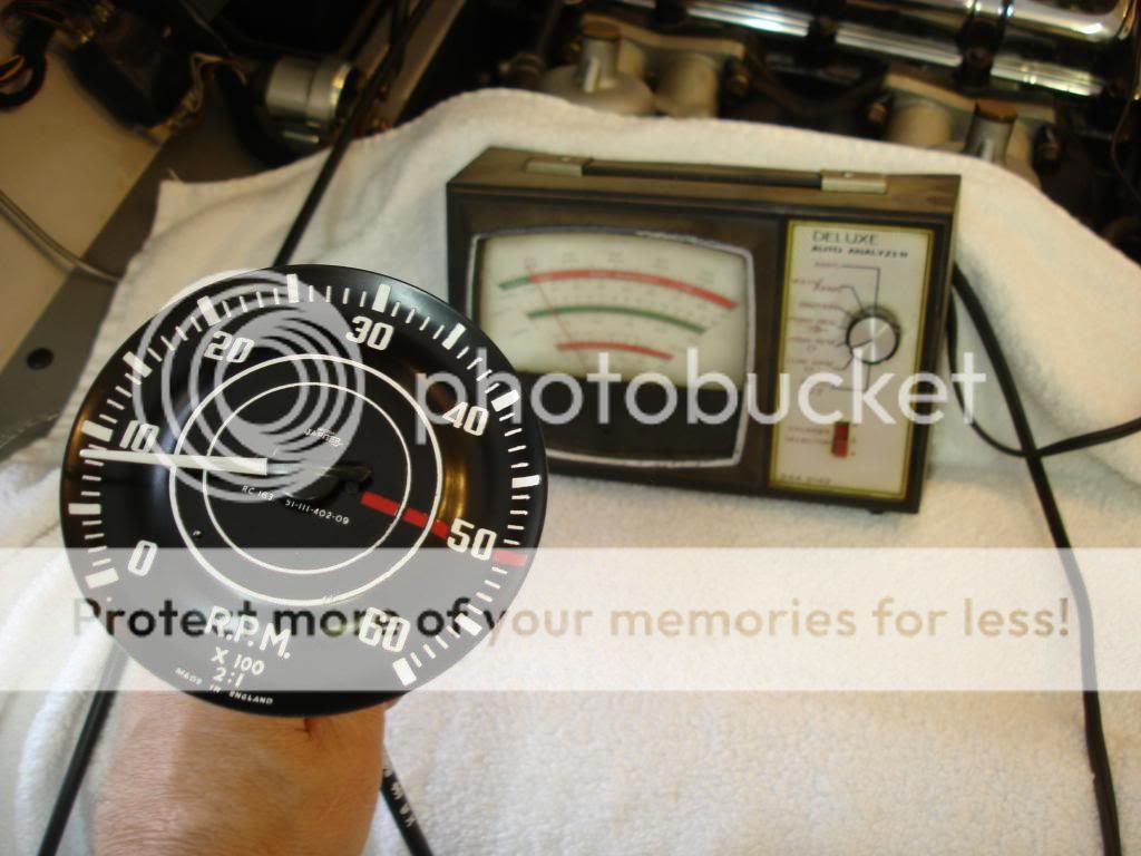
The tach is driven off the distributor at a 1:1 ratio. The distributor is 1:1 with the cam, which is 1:2 with the crankshaft. If you notice, the tach actually says 2:1 right on it's face. I love it when things work out even! The tach has to indicate twice the speed we are actually spinning the input shaft. So, for 3,000rpm indicated, the tach is actually spinning at 1,500 rpm. We need to spin the tach at a known speed to calibrate it. Here is what I chose:


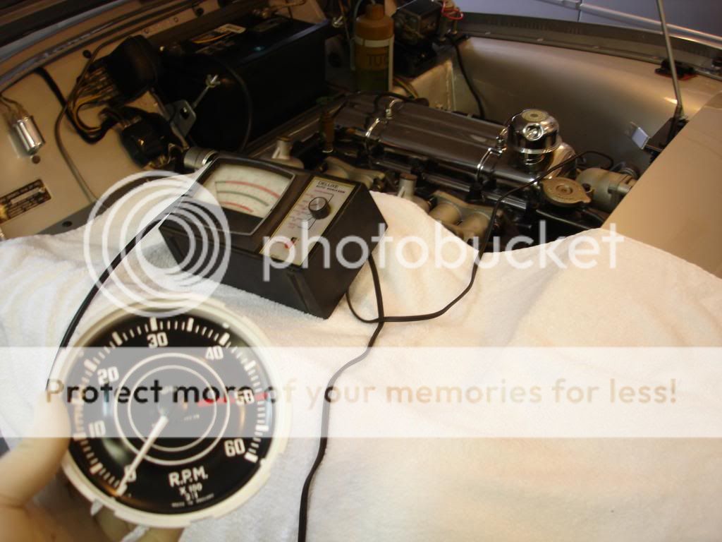
I "happened" to have a spare TR3 sitting around, so I just unplugged the speedo drive and used a spare speedo cable to feed the rebuilt tach. The rectangular instrument is the dwell meter I have left over from the 1970's. Yes. I am that old, and...like this old tool...I'm still hanging in there. Any electronic tach will work, just remember the TR3 is positive ground...so the plus goes to the block, and the negative feed to the coil. So now I have a motor to spin my tach, and another independent way of telling how fast it is spinning. In this pic I have the case installed on the tach...don't install the case for calibration, as you have to remove it to change the calibration. (I don't know what I was thinking) Here is the process:

1) Start the car and rev to a steady RPM, where you want the tach to be the most accurate. I used 3,000 RPM, since that is the middle of the scale. That is where I cruise the most. If you rev to the limit regularly, I'd recommend using 5,000 RPM to prevent a chance of overspeed. The point is that we are dealing with a mechanical instrument, so it will not be perfect at more than 2 points on the dial...idle, and whatever point you pick.

2) See what the tach registers. My first run the tach read 6,000 RPM with the actual engine turning 3,000.

3) to slow the tach reading, reduce the strength of the tach magnet by CAREFULLY!! moving the strong magnet 1 inch from the tach magnet, while the tach is still turning. Hold it about 2 seconds and remove the strong magnet. Recheck the tach reading for accuracy. Repeat if needed to weaken the magnet.

4) To speed the tach reading, we need to strengthen the tach magnet. STOP THE ENGINE! Or just unplug the flexible drive. From the back side of the housing, touch the strong magnet to the tach magnet and slide. You do not have to take anything apart to do this...here is how the housing looks from the back:


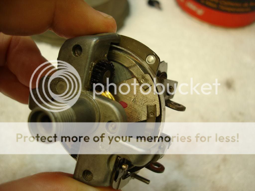
In this pick you can see half the tach magnet. That is where you touch it and slide the larger magnet. Just one side is enough to strengthen it.

5) After repeating step 3 and 4 several times, you will get a perfect calibration. For me, that was exactly 3,000 RPM indicated at 3,000 RPM actual. The final step is to check your idle indication. This setting is controlled by the preload on the clock spring. Remember how we set the needle to line with the small dot, and popped it over the peg on the tach face? That was setting the preload on the needle assembly. If the spring is still in good shape, when you let the engine idle, the indication will be a perfect alignment at the actual RPM. If not, hold the aluminum disc with a finger and carefully turn the needle on the shaft until it is.


6) If you had to move the needle to get a perfect idle indication in step 5, then you now have to recalibrate your high indication. It will only take a very quick pass with your "degouser", since you are likely only off a couple hundred RPM at most. Repeat steps 3-5 as necessary to get a perfect idle and high indication.


7) Now, when you are happy...like I finally was after smashing and rebuilding the tach face...firmly press the needle fully onto the shaft.

You are calibrated! All you needed was some way to spin the tach at a known speed, and a big a%$ magnet! I thought the whole process was pretty cool, but I'm easily amazed!!
 
Last edited:
Similar threads
Thread starter Title Forum Replies Date
R TR4/4A Question about cleaning instrument faces Triumph 8
10musketeer Cleaning Instrument Faces Restoration & Tools 1
edkap2002 TR6 Brighter instrument lights? Triumph 0
Lairhead52 Wanted 78 Spitfire instrument panel lights / lenses Triumph Classifieds 3
LAW75 Instrument Panel Lights Austin Healey 9
bighealeysource LED Instrument Lights Austin Healey 12
EWD TR6 LED instrument conversion / Dimmer. Triumph 25
Crankshaft TR2/3/3A Instrument troubleshoot Triumph 7
steveg Improved Instrument Lighting Austin Healey 2
Crankshaft TR2/3/3A Instrument panel cleanup Triumph 4
PAUL161 General MG LED Dash and Instrument Bulbs POS or NEG ground. MG 8
Gerald_Gordon TR4/4A TR4 instrument panel Triumph 7
K TR2/3/3A The "brass wing nuts" rhat hold the instrument panel on...... Triumph 2
S Instrument Panel Lights Spridgets 6
MGTF1250Dave T-Series TF Dash Instrument Panel Studs Size MG 2
2billydavies TR2/3/3A dashboard/instrument panel on 1958 TR3a Triumph 4
HealeyDave Instrument gauge numbers by year - where to find Austin Healey 2
Jim_Gruber Instrument Bezels for BE Instruments Spridgets 4
Gerry M TR6 Instrument panel light bulbs Triumph 1
L Instrument O rings and switch plate mounting Austin Healey 4
Nelson Instrument bulb replacements Spridgets 14
T current instrument rebuilding info from Nissonger Austin Healey 3
M TR4/4A tr4a instrument knob removal? Triumph 9
T XKE Series 2 Instrument Panel Jaguar 2
M Instrument lights, etc. Triumph 8
AH100M 100/4 Instrument panel silver paint Austin Healey 5
Tinkerman TR2/3/3A TR3A Dash and Instrument Cluster Installation Triumph 11
Tinkerman Bench Testing a Wired Instrument Cluster Triumph 7
ekamm TR2/3/3A removing tr3 instrument panel Triumph 15
Tinkerman TR2/3/3A 1960 TR3A Instrument Cluster Ground Post Screw Triumph 9
Tinkerman Instrument Cluster Assembled, YEA ! Triumph 22
Tinkerman TR2/3/3A Instrument Cluster TR 3A Triumph 14
J TR2/3/3A TR3A instrument restoration Triumph 11
Nelson New instrument lamps Spridgets 10
HerronScott TR4/4A Smith's Instrument List for TR2-4A? Triumph 1
Tinkerman TR2/3/3A Instrument Panel TR3, Question about back. Triumph 29
T MGB MGB Instrument Lighting MG 7
B instrument led lamps Austin Healey 12
prb51 TR2/3/3A TR3 instrument lights Triumph 4
J Removing Healy wood instrument panel BJ7 Austin Healey 3
HEALEYJAG BN1-instrument light wiring harness Austin Healey 0
B What is the color inside the instrument. Austin Healey 2
AUSMHLY A brighter instrument gauge light bulb Austin Healey 59
jjbunn Instrument Dial Rims Triumph 12
Tinkerman TR2/3/3A TR3 Instrument Glass Triumph 5
6 Dash Instrument Conversion: BJ8 > BT7 Austin Healey 3
PAUL161 Instrument Bulbs MG 12
S Spitfire 74 Spitfire instrument panel, Walnut or Teak? Triumph 5
M 87 XJ6 Instrument Problem Jaguar 3
2wrench TR6 Instrument & other bulbs for TR6 Triumph 5

Similar threads

Top