• Hey there Guest!
    If you enjoy BCF and find our forum a useful resource, if you appreciate not having ads pop up all over the place and you want to ensure we can stay online - Please consider supporting with an "optional" low-cost annual subscription.
    **Upgrade Now**
    (PS: Subscribers don't see this UGLY banner)
Tips
Tips

TR2/3/3A My Push Rod Situation

DornTRoriginal

Jedi Hopeful
Gold
Country flag
Offline
I was interested to read about someone else having a similar problem on a TR6 but mine is, ummmm well different I think.....

I just rebuilt the rocker assembly and installed it today but I could not adjust the valves and the engine was very, VERY hard turn by hand. I installed a rebuilt head a while ago, I got the head used, it had been previously surfaced and "ported" (the person I bought it from was a racer so it was kinda "tricked out" already). I am not sure how much had been removed, it was flat according to my machine shop so we went on ahead and rebuilt it and only vey lightly resurfaced the head, I did not measure it and at the time I had the work done I didn't know what I know now, darn it! Today I did a "rough" measurement between the old head and the new one and there is about a .066 mm difference between the two. It makes sense I am thinking, and pretty reasonable to believe I need to shorten the push rods. Not sure how I am going to go about doing that so any advice is appreciated on that topic.

The other option I have is to purchase new ones, which I will probably need to shorten as well... this may be a good plan based upon all the work that has been done on the head already; First, my original push rods are 5/16", although they are in good shape, according to one supplier, it is better to use 3/8" diameter pushrods since the originals are considered "weak". Second, I did install upgraded springs, valves and guides when I rebuild the head, so stronger is a good idea and will avoid or at least theoretically minimize the occurrence of a potential MAJOR problem.

What suggestions and advice do you all recommend? Here are some pictures of the situation. Thank you all very much!
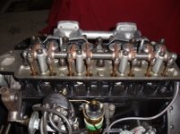
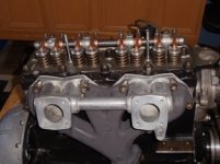
Valves and Rocker arm assbly. (01).JPGValves and Rocker arm assbly. (02).JPG
 

TR3driver

Great Pumpkin - R.I.P
Offline
Today I did a "rough" measurement between the old head and the new one and there is about a .066 mm difference between the two.
Must be a typo or something here. 0.066mm is only about .002", not enough to worry about (or even to measure with a "rough" measurement). The original castings varied by that much.

From what I can see of your photo, it appears you do have a head that has had a lot of metal removed, perhaps around 0.100" (or 2.5mm if you think in metric). That is getting into the territory where the engine might not run well on pump gas, depending on what other modifications have been made to the combustion chambers and so on. If the chambers have been modified as suggested in the Competition Preparation manuals, then you will likely also need a special head gasket to go with them.

So, my suggestion would be to pull the head back off, and find out what you have. Measure the thickness accurately from gasket surface to gasket surface. Stock is 3.325-3.330", so if you find 3.230" then there has been about 0.125 removed.

Also check the combustion chamber volume. Compute the compression ratio and decide if you are willing to live with it. Unless the chamber work is really good, anything over 10:1 is going to cause problems on the street. (IIRC, Kas recommended no more than 11.7 for racing, but that requires racing fuel. Pump gas in the US is much worse today than it was then.) Camshaft makes a difference too, some performance cams will allow a bit more compression.

While you're in there, look for any sharp edges left from the milling process. All exposed edges should be rounded to at least 1/32" radius. Compare the chamber shape to the Comp Prep manual. Check the gasket carefully to be sure it doesn't protrude into the chamber. If it does, you'll need to either buy a custom gasket, or modify one yourself. Modifying the stock composite gasket isn't practical, so you'll need a solid steel or copper one to modify.

One source for shortened, 3/8" pushrods is BFE https://www.britishframeandengine.com/ He stocks them (or at least did) in standard and .100" shorter versions; but can have them made to any length you need.
Or, the Comp Prep manual shows how to shorten the stock pushrods in a lathe.
 
OP
DornTRoriginal

DornTRoriginal

Jedi Hopeful
Gold
Country flag
Offline
Thanks Randall your suggestions and observations seem to be right on. My math is horrible, not a typo, and the measurement does not make any sense. I talked to BFW (Ken) today and I can get custom made rods but it seems that the tappets might be part of the problem, they are not seated correctly. Ken at BFE suggested I try to cut one of my rods in half and tape it together and see if it "fit" correctly and I can get an idea what length I need.

However, I think the tappets are not installed correctly, when I turn the crank the push rods are not moving and the rods are obviously "taller" than they should be. When I pulled out the push rods the tappets in four locations came out of their " chamber" and were lying awkwardly inside the engine. I have been trying to get them to seat correctly but it is slow going. I'll try working on it some more tomorrow. I am trying to "flip" them into place using a magnet, thin wire and a plastic sleeve I made. Needless to say not fun.... They don't seem to want to go down in all the way, wonder if I've bent them?

The machine work on the head was completed by a machine shop and I believe the compression ratio is 10:1 or below according to earlier calculations, however remember my matmatical skills. I did not mention that the head gasket was provided by BFW as well as the 89mm pistons, valves and misc. engine parts. I thnk we have the right stuff?


If I pull the head can I reuse the copper gasket, it’s been coated with sealant and torqued to spec or does it have to be replaced? The engine has not operated yet so maybe I can get away with reusing it?

The good thing about pulling the head is I will get a good look at what's happening and if the tappets are the problem I will be able to check them closely and I'll be able to measure the head correctly. I just hate to have to remove everything....
 
Offline
Why do I hear people keep referring to casting thickness to figure out compression ratio, this would be a very inaccurate way of doing it, you measure the combustion chamber volume, then you need to know the compressed head gasket thickness, the head gasket bore, most are some where around .080" over a stock bore, the bore and stroke, the deck height of you piston, the dish, or dome volume. if not a flat top piston, then enter this data in online compression ratio calculator, and va~la you know know your compression ratio. The danger of buying a head from a racer, is that is has too much cut off it for street use with pump gas, the TR6 head can take massive cuts off it for racing, those cuts if large enough, say, .100", or greater then you get to the point where the stock push rods are too long and you need a custom length push rods, not a big deal, you call Smith Brother Push rods and they will make you any length you need and they are not extremely expensive, for a 6 cyl. engine maybe $125-150 with shipping. I don't think you could hold a gun to my head, and have me put a race prepped head on a street engine without first knowing the compression ratio, without knowing this, would be like playing Russian roulette :smile:
 

tomshobby

Yoda
Offline
When my TR6 head was "cc'd" I found out that the posted casting thickness charts are only approximations. I wanted to use my car for touring and was after 9.8:1cr. After 46,000 miles through 28 States, 3 Canadian Provinces, and a visit to Hap's shop my car has performed better than I had hoped for.

engine 013.jpg engine 014.jpg
 

TR3driver

Great Pumpkin - R.I.P
Offline
Why do I hear people keep referring to casting thickness to figure out compression ratio, this would be a very inaccurate way of doing it,
Not sure if you are referring to me or not, Hap. I agree completely, except that IMO measuring the casting thickness is a simple, valid way to determine if the head has been messed with and, to some extent, how much. Certainly once it has been messed with, then measuring the chamber volume is the only way to accurately determine compression ratio.

However, how much the casting has been shortened does put something of an upper limit on how much the volume has been reduced. I've never heard of anyone adding metal to the chamber, only removing it. So if the casting is still at it's original thickness, then the head is unlikely to have been modified.

The chamber volumes weren't even all the same from the factory; later heads had a larger volume to keep the compression down when used with 86mm liners instead of the 83mm liners originally used on the TR2-3A.

"Russian roulette" ... Exactly!
 

TR3driver

Great Pumpkin - R.I.P
Offline
However, I think the tappets are not installed correctly, when I turn the crank the push rods are not moving and the rods are obviously "taller" than they should be. When I pulled out the push rods the tappets in four locations came out of their " chamber" and were lying awkwardly inside the engine. I have been trying to get them to seat correctly but it is slow going. I'll try working on it some more tomorrow. I am trying to "flip" them into place using a magnet, thin wire and a plastic sleeve I made. Needless to say not fun.... They don't seem to want to go down in all the way, wonder if I've bent them?

I think it unlikely that they are bent. The tappets are very hard and would most likely break before bending. However, they are a very snug fit in their bore, so it is really tricky to get them lined up while working through the pushrod tubes (with the head in place). Not even all that easy with the head off!

The machine work on the head was completed by a machine shop and I believe the compression ratio is 10:1 or below according to earlier calculations, however remember my matmatical skills. I did not mention that the head gasket was provided by BFW as well as the 89mm pistons, valves and misc. engine parts. I thnk we have the right stuff?
Well, could be. I don't know if the gaskets that Ken supplies are already cut, or are simply capable of being cut (he didn't have any when I picked up my set of 89mm liners, need to buy a couple myself). I believe the instructions in the Comp Prep manual (which your machinist may or may not have followed ?) call for trimming back the edge of the chamber even beyond the edge of the liners, and then blending the top edge of the liner out to match. Maybe the gasket is cut to allow that, but maybe it isn't.

If I pull the head can I reuse the copper gasket, it’s been coated with sealant and torqued to spec or does it have to be replaced? The engine has not operated yet so maybe I can get away with reusing it?

Assuming it's a solid copper gasket (not copper clad composite like the originals), then you can probably just refresh the sealant and reuse it. Mordy (the guy who makes the solid copper gaskets for BFE) used to recommend that they be annealed before reinstallation, but he and others have found that it usually isn't necessary.
The good thing about pulling the head is I will get a good look at what's happening and if the tappets are the problem I will be able to check them closely and I'll be able to measure the head correctly. I just hate to have to remove everything....
I don't blame you in the least. Likely I would do the same, cross my fingers and try it out. But realize that uncontrolled detonation can quickly destroy an engine, you are literally playing with fire here.

I believe this was caused by detonation only under cruise conditions (caused by other problems, not too high CR), but I didn't know there was a problem until ...


tomshobby

Yoda
Offline
Hi Randall,
When I purchased my 6 it only had 40,000 original miles and a few broken rings and the rings had broken the top edge off a a couple pistons. I have wondered why it happened. One theory I have is that the car sat for long periods over the years and when starting the cyl walls may have been dry and possibly some rust. This causing drag on the rings and leading to the broken rings and pistons after years of this happening.
Your thoughts?
 

MDCanaday

Jedi Knight
Offline
I can still recall the look the machine shop owner gave me when I asked
to have 125 thou taken off my tr6 head......"Thats an 1/8th of an inch are you sure??"
Well ,I said,how else will we get to the 47CC chamber we need to get 9/1 comp??
Getting the shorter push rods was a matter of a phone call....
MD(mad dog)
 

TR3driver

Great Pumpkin - R.I.P
Offline
Hi Randall,
When I purchased my 6 it only had 40,000 original miles and a few broken rings and the rings had broken the top edge off a a couple pistons. I have wondered why it happened. One theory I have is that the car sat for long periods over the years and when starting the cyl walls may have been dry and possibly some rust. This causing drag on the rings and leading to the broken rings and pistons after years of this happening.
Your thoughts?
Seems unlikely to me, but could be, I guess. I had a TR3A engine where the rings in #3 had rusted to the wall pretty badly and left a big groove, which apparently broke the rings in that cylinder; but the piston was OK.

Having no money at the time, I stuffed a new set of rings in it and put it back together, even though I could still see where the rings had rusted to the wall. That engine actually ran pretty good, burned less oil than I had expected and was still running 7-8 years later when I finally replaced it. It did sometimes make a funny noise at idle though, which I think was the piston slapping around in the oversize section of cylinder.
 
Offline
Randall, more than casting thickness can effect chamber volume, for example valve height, if a head had several valve jobs in its lie the would raise the valve height, and thus increase chamber volume. Now in Tom;s above pictures, you'll see a glass CC burrete used to do this, and if someone does this work all the time, like me, then this is the tool to have, but for a novice, or occasional engine builder, you can go you local drug store, and get a feeding tube syringe, and do the same thing, they only cost a couple of dollar at most, that a piece of Plexiglas ans some grease, and you have what you need to properly figure you chamber volume.
 

TR3driver

Great Pumpkin - R.I.P
Offline
Randall, more than casting thickness can effect chamber volume,
Yes, that was exactly my point. But again, pocketing the valves will increase the volume, lowering the compression ratio. The thickness of the casting still puts an upper limit on how much the volume was reduced and hence the increase in compression ratio.

So if I measure a head and it's still the stock thickness, I don't have to worry about chamber volume (for a stock street motor). If it's short by 0.1" or more, then it's time to break out the burette, plexiglass, dummy valves, smear of grease for the valve seats, colored water and so on. Maybe that's no big deal for you, but it seems like a lot of work to me, compared to hanging a caliper across the gasket surfaces. The thickness measurement is also a lot easier to explain to someone who's never done it.
 
OP
DornTRoriginal

DornTRoriginal

Jedi Hopeful
Gold
Country flag
Offline
I felt really good yesterday... I was able to get all the tappets back in place, measure everything and ordered the push rods, what a great feeling!
What I learned; I did not realize a tappet could drift off into another chamber, what I think happed was one tappet was upside down (hard to see cuz it is black and my eyes are not as good as they once were) and I was trying to push the other one tappet onto it, naturally it did not budge. The binding was from the push rod that became wedged by the cam where there was no tappet (this happened in three locations??) so the "bugger" dropped into the void too far and was getting stuck. To get the tappets to move I made a sleeve out of some plastic drip pipe tubing by slitting it in half and cutting off the edge so it could be inserted into the push rod hole and surround my magnet, I was able to slide the magnet into the tube and is didn't stick to everything on the way and I was able to get'em to move around a bit easier. I maneuvered the tappets back into the correct holes, and flipped the upside down tappets "right side up" using a covered piece of copper electric 12 gauge wire with a slight bend in the end (as suggested by the TR6 driver with a similar problem), my magnet and a wooden dowel. Once I figured out the situation it was not that difficult to do.... I realize now that I need to be a bit more careful when removing the push rods.

The good news is, I think, I don't have to pull the head off! I ordered shorter, stronger push rods that are one hundred fifty thousand shorter (.150 mm ?) and 3/8 inch diameter (British Frame & Engine) as Ken and I discussed we think this will be sufficient for the thickness of the head. I should be able to get them installed early next week.

I don't know if I will ever get around to really figuring out exactly what my compression ratio really is, I think I going to just tell everyone it is 10:1. :>)

Thanks everyone for all the help and advice, I have learned so much so far on this project and continue to realize new things it is an amazing experience. Today I am working on centering the front brake calipers on the rotors and installing the brake lines. No doubt I’ll need some advice along the way, there’s also two car shows nearby today, so it gonna be a great day!


Thank you all so much!
 
Similar threads
Thread starter Title Forum Replies Date
K TR2/3/3A Clutch and Brake Master Cylinder push rod stop bolts? Triumph 15
Joe Reed MGB Clutch Slave push rod...past its prime MG 2
GTP1960 TR2/3/3A Clutch slave cylinder / push rod alignment Triumph 10
F BT7 3000 - Push rod problem on clutch slave cylinder Austin Healey 7
tahoe healey Clutch master cyl. push rod Austin Healey 2
SMGoose Push rod return spring Triumph 7
T TR2/3/3A TR3b Master cylinder push rod clevis Triumph 2
S TR4/4A Leaking push rod tubes, TR4a Triumph 7
T Bugeye clutch MC push rod length Spridgets 6
Mickey Richaud Brake M/C Push Rod Spridgets 8
Mickey Richaud Brake M/C Push Rod MG 2
K M/C push rod adjustments Spridgets 4
R clutch push rod replacement question Spridgets 6
T TR4/4A ? on TR4A clutch shaft - wear @ push-rod attachment Triumph 6
I push rod question Triumph 8
drooartz Clutch push rod Spridgets 13
A TR4/4A TR-4 cylinder head push rod tubes Triumph 2
B Spitfire Decipher this Spitfire engine and a push rod query Triumph 3
Bruce_B Push Rod for Brake Master Cylinder Spridgets 9
H push rod length help Austin Healey 1
pan Bent push rod Austin Healey 3
Russ Austin Push Rod looks a little short Triumph 14
V TR6 TR6 Push Rod Length Triumph 1
AUSMHLY brake pedal push rod adustment - YIKES ! Austin Healey 9
B MGB while driving engine cuts out if I let off or push more throttle it comes right back on MG 5
C MGA Change a pull starter to a push button system MG 6
PAUL161 T-Series Bent Push Rods MG 34
R J-H no longer needs a push! Other British Cars 6
K Restoring Horn Push Button Austin Healey 12
Joe Reed General MG Early Midget horn push on Personal wood rim steering wheel... MG 3
Patrick67BJ8 Brake Pedal Vary Hard to Push Down and Brakes feel like there's no Booster on my BJ8 Austin Healey 27
Got_All_4 TR2/3/3A Push switch for washer fluid pump Triumph 4
Lukens TR2/3/3A Anyone ever see a push/pull throttle mounted on the dash? Triumph 4
T timmers 67, push rods and lifters Austin Healey 4
Martinld123 Push button on top of new H6 carbs float bowl from Moss Austin Healey 3
KVH TR4/4A Rocker Shaft Lubrication, and Issue with Push Rods Triumph 1
S TR2/3/3A copper gasket sealer and push rods Triumph 10
J Healey 100 -- Broken rocker and bent push rods !!! Austin Healey 7
Perrymip TR2/3/3A Starter Solenoid Push Button Triumph 11
P Grounding of Horn Push-Bugeye Spridgets 4
Kleykamp TR2/3/3A hollow push rods ? Triumph 6
M stainless push button snaps for convt boot Austin Healey 2
F Replacing the horn push adjustable steering wheel Austin Healey 7
C Wiring new Mota Lita horn push into my MG Midget Spridgets 6
Donalvin removal of push-pull dash control buttons Triumph 5
BugeyeNJ58 Push or Pull - Electric Fan Spridgets 3
G Push'in Springtime Spridgets 3
6 elect. fan..push or pull Triumph 16
S TR2/3/3A tr3 unsoldered push in connectors Triumph 3
justin_mercier Source for a push/pull DPDT switch? Triumph 13

Similar threads

Top