• The Roadster Factory Recovery Fund - Friends, as you may have heard, The Roadster Factory, a respected British Car Parts business in PA, suffered a total loss in a fire on Christmas Day. Read about it, discuss or ask questions >> HERE. The Triumph Register of America is sponsoring a fund raiser to help TRF get back on their feet. If you can help, vist >> their GoFundMe page.
  • Hey there Guest!
    If you enjoy BCF and find our forum a useful resource, if you appreciate not having ads pop up all over the place and you want to ensure we can stay online - Please consider supporting with an "optional" low-cost annual subscription.
    **Upgrade Now**
    (PS: Subscribers don't see this UGLY banner)
Tips
Tips

TR2/3/3A Inner sill opinion

OP
F

Frank Canale

Jedi Warrior
Silver
Country flag
Offline
IMG_0060.jpg
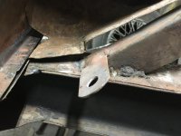
this is the original battery box as I was drilling out the spot welds to remove it.
IMG_0135.jpgPieces parts of the new battery box, copied from the original.
IMG_0002.jpgBox spot welded together no bottom yet.
IMG_0813.jpgbottom with dimpled drain hole. I got lucky to find a drawing in the service manual with the drain location since I did not have a bottom to copy.
IMG_0812.jpgbottom with drain. I did take a liberty and used a hose barb for the drain. The hose barb is still the correct diameter as the original drain tube. Once the bottom was spot welded in I ended up with a little oil canning so minor heat shrinking took care of that.
IMG_0811.jpg
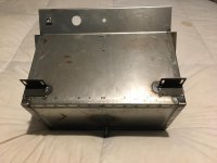
finished battery box ready to install. Tush was very helpful in letting me know about having to cut the fire wall to get the top flange under the scuttle. That will come down the road, for now it is out of the way. This was a fun project and looking back has helped me see that there are a lot of parts that have already been repaired and are ready to be added to the puzzle when the time comes.
The last photo is of the back with mounting brackets.
 

Attachments

  • IMG_0814.jpg
    IMG_0814.jpg
    41.1 KB · Views: 50

sp53

Yoda
Country flag
Offline
Nice work Frank I forgot you fabricate so well. If you go with an OD, the relay bolts to the back of the box. I drilled mine out after the box was in, so no biggie. The holes get counter sunk; I guess so the battery does not get poked with the screws. I copied how John did it by pulling a bevel headed screw back with a socket for a spacer to make the depression.
 

CJD

Yoda
Country flag
Offline
Nice...your box deserves the BH stamp of approval! I’m jealous you have a spot welder too.
 

DavidApp

Yoda
Gold
Country flag
Offline
That is a great looking battery box. Probable much better than the one that came with the car from Triumph. I did add the plastic insert to protect the paint.

David
 
OP
F

Frank Canale

Jedi Warrior
Silver
Country flag
Offline
Thank you all! I got to spend a few extended hours last night and am very encouraged. There are specific mounting points that I have decided to look at using the floor pans and the transmission tunnel to help with positioning the front clip. I also decided that I am going to have to slow down and look at all the mounting points and figure out the best position that limits the amount of corrective work. I am learning how to fudge here and there to get the best results. For now a lot of clamping, measuring, and looking. Frank


TimK1955tr2

Senior Member
Offline
Hi Frank, looks great, excellent work! Would you mind revealing your welder set up? I have a small TIG welder but I think I am going to move to MIG when I take on similar projects regarding my car... thanks in advance! Tim
 
OP
F

Frank Canale

Jedi Warrior
Silver
Country flag
Offline
Hi Tim, I am out of town but I will give you as much as I can from memory. My welder is a lincoln TIG 300/300. This is a 25 year old transformer welder I bought new. I am using a weldcraft wp 20 water cooled torch. I use the water cooled torch because that is how I set the welder originally. For welding light gauge sheetmetal patches an air cooled torch will work just fine. I use 1/16" 2% thoriated tungsten that I sharpen at approximately 30 degree angle. An easy trick is to chuck the tungsten in a cordless drill and spin it as you sharpen it on your choice, bench grinder, angle grinder, dreamel, belt sander. I know you are supposed to have a dedicated grinder for your tungsten but it is not that critical for steel sheetmetal patches. I use a gas lens tungsten holder and cup to aid in extending the tungsten past the cup and better gas shielding. I use DC negative polarity. I set the maximum amperage to 45 amps and my welder has a foot pedal so I can start quickly and back off the amperage to soot my need. If I start to burn thru I can stop befor if makes a big hole Let it cool off and fill the hole or just back off the heat add a little filler rod. I usually use .035 diameter filler rod. I find it easier to use filler rod that matches the thickness of the metal I am welding, that way the heat will melt both equally. If the rod is bigger it takes more heat to melt the rod than you need to melt the parent metal or you use enough heat to melt the parent metal and the rod does not get hot enough to bond. There are many ways to weld a patch panel in but this is how I do it. I make the patch to fit as close as I can with no gaps and no tight spots. I do not have an oxygen acetylene torch but I use the tig torch to fuse the metal together and use as little filler rod as possible. I fuse long stretches as I can to keep the warpage to a minimum,( I know it sounds strange but it works) then once all the welding is done the welds are hammered and dollied flat. This technique almost eliminates grinding which thins the metal and can add warpage. I have always preferred tig welding for the control and ultimately for the weld quality. Mig welding looks easy but it also takes a good setup as to wire size, current selection, and wire speed. I will make a couple or recommendations to anyone doing any level of restoration. I do not get any compensation for these recommendations. Welding tips and tricks is a great you tube site to see what the welds should look like as it is being welded. David Gardiner Is an Australian fabricator that has a DVD that is simply incredible. He shows techniques to bend and form metal using basic hand tools. The TV shows all have very specialized equipment that makes it easier and faster but I don't have room for all that equipment or a budget for it either. All my equipment and tools have been accumulated over 40 + years. The DVD has helped with the metal forming and especially welding sheetmetal. This DVD is where I viewed his gas welding technique. I gave it a try and fell in love with it. You can google David Garner to see his work and order the DVD. Hope this helps, If you need any clarification I will be happy to follow up with more info. Frank
 

TimK1955tr2

Senior Member
Offline
Hi Frank, wow great info, thanks so much, I guess I assumed MIG for some reason, sorry! I think the missing link for me is the hammer and dolly work post-weld.

When you say "fuse long stretches" does that mean tack the piece in and then jump with more small tacks and short welds to keep the heat down in any one area? Not one long weld right?

I will certainly be saving your post for future reference, sorry if I hijacked the thread, thanks again! Tim
 

CJD

Yoda
Country flag
Offline
Tim, if you have a TIG set you are golden. I only used MIG because I had not budgeted for the TIG until just this year. The beauty of the TIG is you can limit to just the amount of heat you need, and no more. The only down side is TIG takes much more skill than MIG. I can take one of my kids who knows nothing about welding and have them running pro looking beads in 15 minutes on the MIG. I got my TIG 9 months ago and still working on technique...definitely requires a higher skill level. The difference, I can practice on Dr Pepper cans...MIG would blow through anything that thin!

I would still tack tack the metal at intervals, as you must hold it together in order to weld it. You can run longer beads as you keep the heat down, and therefore the warpage down.

Once again jealous, Frank! You've got all the top end toys.
 
OP
F

Frank Canale

Jedi Warrior
Silver
Country flag
Offline
Yes I do tack the pieces in place but say the patch is a 3 inch square. I would tack the corners a tack in the middle of each side. Hammer and dolly the patch so it is flush with the parent metal. Then I would do a continuous weld to one side. Check that the next side is flush, hammer as needed. This is key that you keep the patch flush before welding. If it is not flush there will be a gap that will be more difficult to weld. You will have to add filler metal and this will be hard to dolly then you have to grind and you end up with thin warped repair. The better the fit the less heat needed because you spend less time in an area. Try and keep the heat consistent. That is what minimizes the warpage. Another thing that helps me do to my age is that I use cheap reader glasses to help see the weld puddle. If you can not see the puddle you will have trouble. You have to be able to see if the patch starts to move( open up, or become not flush) so you can stop and correct. Tig welding may seem slow but with practice it gets pretty fast and you pick up time not grinding so much. John, I seem to remember you have a mill and a lathe and made a gear to repair the lathe. I don’t have either but have used both but not to your level. A different skill set that I am also jealous. This is a great forum where we can share information to shorten the learning curve ultimately to help each other.
 

sp53

Yoda
Country flag
Offline
One can always use the bullet-headed commercial carpenter approach and run a sheet-metal screw into the pieces for a tack, like you are building a building with metal studs. That way you can remove the screw easily and move it and say, “that is not going to work; it does not look correct”. Really, I am envious of a good welder.

Anyways, Frank I read you were saying the fender bolt holes did not seem to line up well. IMHO that is normal; if you look at the hole diameter of the holes running along the top of the fender, the holes in rear by the firewall have a larger diameter for the bolt to enter. I found putting the fender bolts in at the A post pushes the fender forward and then a 12 inch punch into the fender to the inner fender and then push forward helps with the alignment.
 
OP
F

Frank Canale

Jedi Warrior
Silver
Country flag
Offline
Still fiddling and measuring. There is a lot to look at and still a lot to learn. It still amazes me at the knowledge contained in the forum that can look at something and identify right or wrong from their experience and are willing to help others. Refreshing in a world of me, me, me. Thank you all.
IMG_0816.jpg This is on the driver side of the front clip at the tab where the slave cylinder is on the transmission. The flange has a radius in it and appears to be factory but not sure and not sure the purpose unless something passes under the flange. Did not want to change anything till I know how it should be.
IMG_0817.jpg This is the passenger side of the transmission tunnel. What is the purpose of the mouse hole. It is possible this was an over drive tunnel but I am not sure. It has the hole for the earlier transmission with the dipstick. It also has the hole on the driver side to check the oil level. It also had an extra large hole on top towards the front that did not line up with anything. I believe this car has had many alterations during its life. Frank
 

CJD

Yoda
Country flag
Offline
I built the kids some Optimist Sailboats in 1999. The boat was designed in Clearwater Fl, I got the plans from Scottland, and had help from builders in Australia and New Zealand. That's when I came to the realization that the internet had changed everything!

The hole in the first pic is where the clutch hard line attaches to the clutch flexible hose.

In the second pic, yes, the lower hole is where the OD speedo cable comes out. The tunnels were not different between the OD and non OD cars, and the hole gets covered with the seal for the handbrake later. The hole on the left was also used as an exit grommet location for the OD wiring. The early tunnels did not have a hole for the oil fill, as it had not been moved to the left side yet, and filling was through the dipstick hole. I would have to see the hole up front center. The only one that comes to mind is the battery box drain, but that is only 1/2".

You probably know the large center hole is for the shifter, and the one to the rear is access for greasing the U-joint, which is inaccessible from the bottom of the car because of the cruciform box on the frame.

So it sounds like your tunnel is normal for an early car, before the dipstick was removed from the tranny.
 

Graham H

Jedi Warrior
Country flag
Offline
I think the bracket should be twisted so the hole faces down to the clutch slave cylinder.

Graham
P1010120.jpeg
P1010159.jpeg
 
OP
F

Frank Canale

Jedi Warrior
Silver
Country flag
Offline
Thank you Graham, When I repaired the frame I seem to remember that the tab was pretty mangled so I straightened it. Now that I know how it goes that will be an easy fix.

Thank you John for the transmission tunnel explanation. The large hole on top was cut by the PO and does not line up with anything on my transmissions. It had a home made cover screwed over it.
IMG_0429.jpg
My question about the first photo was not very clear. This is my first attempt at editing a photo that might help.
IMG_0816 (1).jpg does the curved flange look right? It appears to be original but not sure.
 

Attachments

  • IMG_0816.jpg
    IMG_0816.jpg
    58 KB · Views: 40

sp53

Yoda
Country flag
Offline
The holes on top of the shifting tunnel might line up with the OD cut out switches. Good idea probably for access.
 

Graham H

Jedi Warrior
Country flag
Offline
I have some photos of the area you are looking at but they are not very clear but may be of some use.

Graham
P1010086.jpeg
P1010101.jpeg
 
Last edited:

Graham H

Jedi Warrior
Country flag
Offline
I just had a look at that bracket and the shape of the inner fender at the bottom where your arrow is is flat the same as my photo above on the other side. The bracket has some raised bits to improve rigidity.

Graham
IMG_1764.jpeg
 
Similar threads
Thread starter Title Forum Replies Date
Jim_Stevens For Sale New TR2-3A inner sill assemblies Triumph Classifieds 3
J TR2/3/3A Body Restoration - Inner Sill Replacement Triumph 38
J TR2/3/3A inner sill rust prevention Triumph 1
71TR6 TR2/3/3A Inner sill or floor pan- which to replace first? Triumph 5
J TR2/3/3A Inner sill replacement procedure ? Triumph 5
Scot1966 For Sale New TR6 / TR4 passenger side rocker panel & inner sill -FREE- Triumph Classifieds 2
C Inner Sill Assembly Should i spend extra money on kilmartin brand??? Austin Healey 4
K Link to pic of 4 inner sill install without floor? Triumph 0
W Inner sill panels Spridgets 3
B TR2/3/3A Need advice TR3b inner sill replacement Triumph 16
M_Pied_Lourd TR2/3/3A TR3A Inner Sill Replacement Advice Triumph 7
M_Pied_Lourd TR2/3/3A TR3A Help with Resto Pics Please Front Inner Sill Triumph 19
O TR2/3/3A Help with TR3 inner sill removal - blind welds? Triumph 5
ekamm welding tr3a inner sill Restoration & Tools 2
M_Pied_Lourd TR2/3/3A TR3A Inner Sill Repair Question/Advice Triumph 95
K TR4/4A TR4A :Anyone have a pic of inner sill in place.... Triumph 2
F Inner rocker [sill] panels Spridgets 11
T TR4/4A TR4/6 inner sill replacement - body on/off frame Triumph 1
A TR6 TR6 B-post to inner sill connection Triumph 3
tr6web Outer and inner sill [rocker] installation Triumph 5
R Inner Sill, Which way ? Spridgets 2
J TR4/4A Strange Problem Fitting Inner Fender Triumph 18
D TR4/4A TR4 inner ball joints Triumph 8
R 2500M Inner Fenders - are they the same as a Vixen 2500? (Also Tire Size) TVR 3
SNClocks Gap between inner and outer fenders Spridgets 0
S TR2/3/3A Distributor vacuum advance hook up to the inner plate Triumph 9
M TR2/3/3A TR3 Small Mouth Inner Fender Holes Triumph 3
J Wanted WTB Triumph TR3 inner sills Triumph Classifieds 8
R GT6 GT6 Bearing Part Number Request (Front Axle, Inner Bearing)... Triumph 3
M BJ8 Inner Body Panel Repair Austin Healey 2
chicken Inner Door Seal Trim Position Austin Healey 6
S Inner Body Alignment Austin Healey 0
G 1962 TR3A inner plate # Triumph 8
rr64 Wanted Early MGB Inner Steering Track Rods Wanted MG Classifieds 1
K TR2/3/3A Inner tie rod ball joint. Triumph 6
M TR2/3/3A Front Inner Fender Doublers Triumph 2
F TR2/3/3A Front inner wing baffle measurement Triumph 7
wangdango BJ8 inner battery hold down? Austin Healey 4
K TR2/3/3A Front suspension inner Lower wishbone bush area? Triumph 3
Got_All_4 TR2/3/3A Inner tie rod ends Triumph 4
F TR2/3/3A Question: front inner wings Triumph 11
TAS525 TR2/3/3A Missing zerk from inner tie rod end Triumph 7
T TR2/3/3A Drive end of speedo inner cable to large for pinion Triumph 2
M For Sale 2006 Aston Martin DB9 - Get in Touch with your Inner James Bond Other British Classifieds 2
G TR4/4A Inner Door Reassembly Questions Triumph 4
aero3113 Front Hub Inner Bearing Seal Austin Healey 7
Feathers 289I inner tie rod end. TVR 0
D TR4/4A inner tie rod ball joint tension Triumph 0
F TR4/4A TR4 inner and outer sills Triumph 2
W TR2/3/3A Fabricating inner sills? Triumph 39

Similar threads

Top