• The Roadster Factory Recovery Fund - Friends, as you may have heard, The Roadster Factory, a respected British Car Parts business in PA, suffered a total loss in a fire on Christmas Day. Read about it, discuss or ask questions >> HERE. The Triumph Register of America is sponsoring a fund raiser to help TRF get back on their feet. If you can help, vist >> their GoFundMe page.
  • Hey there Guest!
    If you enjoy BCF and find our forum a useful resource, if you appreciate not having ads pop up all over the place and you want to ensure we can stay online - Please consider supporting with an "optional" low-cost annual subscription.
    **Upgrade Now**
    (PS: Subscribers don't see this UGLY banner)
Tips
Tips

TR2/3/3A Recipe for a TR2

wifegonnakillme

Jedi Hopeful
Offline
X2 on taking the time for pictures. Just finishing my engine up and my stock of photos plus yours should see everything going back together seamlessly... well, hopefully :smile:
 
OP
CJD

CJD

Yoda
Country flag
Offline
So, a quick update...

DSC05807.jpg


DSC05808.jpg


The early bullet nosed starter, ready to go in.


And done.


Now starting on the handbrake. This is the retaining bracket and bolt on the right rear of the differential.


Spring end of the cable to the rear, and now the bracket gets pinned to the belcrank.


The front of the cable has a bracket on the frame.


Take the time now to make sure the grease fitting point in a convenient direction. It'll save years of frustration...unless you have a lift like JP!


Here is the handbrake all installed and ready to use. The fork at this end of the cable has the adjustment. Just continue to tighten the fork until the cables along the back of the differential only just slacken when the handle is full forward.

Note...the early brake lever uses a crappy Bakelite plastic material for the black grip. Simply grabbing the handle is enough that I have broken 3 of these handles! I have to assume the originals were of better material, because the one's I'm getting from Moss are too brittle to use.


Handbrake all done.


In the dark shadows of this pic you can just make out the down pipe for the exhaust.


My Ebay exhaust system. It fit, but the muffler is about 1-1/2 inches longer than original. I had to beat and re-weld the front to fit inside the frame members. Tight fit, but it worked in the end.


Here is the downpipe going back to the center of the frame cruciform.


Then the muffler with the pipe forward to the cruciform...followed by the tail pipe. I put them all on, but did not tighten them yet. The key is to work from the center cruciform mount outward.


This center mount is a real bear to get right, but it is worth every minute you spend on it. If you just install it and don't check clearances, you'll fight it for a long time with bangs and rattles as you drive.
 
OP
CJD

CJD

Yoda
Country flag
Offline


This is the installed fuel shutoff valve.


Time for the clutch save cylinder. Now, as simple as this part is...it has at least a dozen variations in installation that can screw it up. I also learned that some of the parts drawings are flat wrong. But...here is the way mine fits. It's the only way it will work on my car. The TR3A I had was very different!?! Here goes...


That's it! Seems simple now...but it took a while just to figure out which side of the bell housing and mounting plate the cylinder needed to go. Let's adjust the play now.


With the spring removed, turn the adjusting rod until all the play is taken out of the clutch fork.


Once you cannot move the lever, stop. This is where the slave cylinder piston is bottomed in its bore, and the throwout bearing is touching the clutch forks.


Now screw the lock nut to within .030" of the adjusting fork...use a feeler gage to know how far.


Now screw the rod towards the fork until the lock nut just touches the fork. Then tighten the nut.


Install your return spring and your done!


The front spring tower frame brace.


The drive shaft. The slide goes forward.


The idler arm assembly. This is another part in which the drawings in the manual are flat wrong! I had to refer to my disassembly pics to get it right.


Tie rods. Be sure that you are consistent with the ends, so that turning either one the same way will do the same thing. I.e. Toe in or out with a downward rotation.

Now I turned to a few clean up items.


The vacuum line for the distributor normally passes behind the coolant bypass hose. I had it in front...which the judging guide says is not necessarily wrong. But I decided to move it to the more common routing.


It turned out my car came with a TR4 thermostat housing. I am replacing it with the proper TR2/3 variety. By the way...I could not find a repo for this! The TR3 uses longer through bolts, and the capillary for the temp gage is at a right angle to the engine.


Here I am setting the crank to 3 degrees before TDC to set initial timing. I have taken the cap off the distributor.


And I hooked an ohm meter to the points. I then loosened the distributor and slowly turned it clockwise until the points just opened. This will set the initial timing to very close to 3 degrees. I will fine tune the setting once the engine is running.


Radiator...the old Frankenstein one cobbled from 3 old ones in my body work post!


Finally, the road draft tube...

The tube is in, but I will have to fab the bracket that holds it unless it turns up in another box. The brackets are NLA from the big 3.

That's about it for now...
 

Popeye

Darth Vader
Bronze
Country flag
Offline
Well done - rather well "doing"!

Is it just me, or do others see a Rolls Royce when looking at the radiator?
 
OP
CJD

CJD

Yoda
Country flag
Offline
Fuel shutoff is that specific to tr2?

No, TR3's had it for a while. It left at some non-specific time before the 60k TR3A. They had a rep for leaking, so even the Judging guide gives you a pass if you bypass it.
 

DavidApp

Yoda
Gold
Country flag
Offline
They must have continued to include the shutoff mounting lug on the frame after TS 60000. My car is TS 75524 and I have the mounting lug on the frame.

David
 

Tr3aguy

Jedi Knight
Country flag
Offline
Hey when you get that thing finished up bring it on to D.C. For a visit and I will let you put it on the lift for the first service..... of course I may have a spray gun handy for some tutorial technique expertise as well😄👌🏻
 
OP
CJD

CJD

Yoda
Country flag
Offline
I wouldn't let me too close to your lift...it may go missing!!


Continuing with the inverted flare nuts...this is the only company in the world I have found that carries them. The big three suppliers are even back ordering their brake lines, and I suspect it's because they are having trouble sourcing these too.


But I managed to get a pack of them, so I could continue with my brake lines.


If you have ever done double flares, this will be pretty dull. But the following is a quick and dirty about how to do it easily. The double flare kit runs about $19. In this pic I have slid the flare nut onto the line, and then captured the line with 3/16" of tubing extending out the top. The disc you see is the "double flare" bit for the first step. It is VERY important to de-burr the tubing before trying to flare it. For many years I could not get a double flare to save my life...I finally realized it was because I simply cut the tube with a tube cutter and then tried to flare it. Tubing cutters leave a very sharp edge inside the end of the tube, and this edge cuts into the tooling bit. After a couple flares the tubing has gouged the bit so badly that it is unusable.

The solution is to de-burr! You will never have any trouble if you do. Notice I am also using a good bit of lubricant, to easy the operation.


Now we use the little vise tool to compress the bit onto the bit. This will form a "bubble" in the end of the tube.


Now the vise goes on without the double flare bit, and you compress the bubble into a nice flare.


And that's all there is to it...other than the 2 months it took to get the correct inverted flare nuts!?!


I ended last week with the downdraft tube. As I stated, it is retained with a small bracket and spacer that mounts to the rear oil pan bolt. I looked all over for the brackets...NLA. I cut this one from 14 gage steel.


And here I have installed the braided fuel line from the shut-off valve to the fuel pump.

I realize some of these items are in odd order. That is frequently because of the order they come out of my time capsule boxes. I may be shuffling around, but we'll still get a full TR2 in the end!
 
OP
CJD

CJD

Yoda
Country flag
Offline
At this point I have done about all I can to the frame. It is time to re-install the body tub...thankfully for the final time!!

Before installing, I went around the frame and sprayed every bare bolt and nut with clear lacquer. The lacquer will retain the natural look of the mounting hardware (dark grey) and prevent surface rust. I use satin, so the result is you cannot tell it has been sprayed on.


Now the pads go back on the frame.


Here the body tub came out of the living room. True to form, my little dolly...that has worked for 2 restorations over 7 years...finally died on the home stretch. If only everything would last only as long as you need it, but no less!?!

A moment of silence for my dolly...


The body tub makes it's final flight. For those in the future, you will note that the balance point is apparently just forward of the "B" post...or at the rear of the door opening. I will use this to my advantage, by securing the rear of the tub to the frame first, and then let it lower at the front as I clear everything around the engine.


Once the rear makes contact, I installed the rear mounting bolts to hold it straight as the front comes down.


I thought hard on the handbrake lever...but finally decided that the large bolt that holds it had to come out. The lever can then rotate straight up to slip into the floor hole it needs to go in.


Coming down slowly. Notice the manifolds and accessories can stay attached...but the carbs must come off.


This is the throttle control rod, that connects the accelerator pedal to the carbs. I forgot to mention earlier that it MUST be installed first. I is possible to install it after the body is on...but if you do you will NEVER want to do it that way again!! Be careful not to catch it as the body comes down.


M_Pied_Lourd

Darth Vader
Country flag
Offline
Beauty eh?

Cheers
Tush
 
OP
CJD

CJD

Yoda
Country flag
Offline


Time to make it a car! Here is the pre-restored pedal assembly ready to install.


The early Lockheed master cylinder has several adjustments not seen on the later Girling MC's. I am pointing to the adjustment for the bottom travel of the pedals. Here is how it works...


Manually push the pedals all the way forward. They will likely hit the firewall. So...adjust the nuts I showed you (one set on each side of the MC) until the pedals go as far down as possible without hitting the firewall. That ensures you have full travel of the pedals. Remember to leave about 3/8" clearance for the carpet and wiring that passes behind the pedals too.


The next adjustment is to lightly press each pedal until you feel a slight restriction to the movement. This restriction is when the actuating rod contacts the piston in the MC. You want to remove the free travel up to the point the rod contacts the piston...but no more! If you go farther, the piston will not open the hole to the reservoir to recharge with fluid.


These bolts/nuts set the free travel. Free travel should be at a minimum, but so you can still detect that there is a bit.

Now the clutch and brake pedals are ready to go.


Back to the hard lines. Mine were no good, so I had to bend fresh ones. First step is to pop off the access panel behind the MC.


Note...the repro MC's use 5 screws to retain the top cover. This is an original, having 4 screws. The 5 are less prone to leaking. The 4 are original...one of the many decisions you will have to make during a restoration, concerning functionality vs. originality.


These are the speed nut clips for the heater fitting that passes through the firewall. One screw doubles as the clutch line retainer, so time to install it now.


This is the clutch line going in.


I am using a towel to prevent marring the new paint as I bent the line to shape.


And it gets flared and installed in the clutch hose at the frame bracket. Note the clutch line is 1/4", vs 3/16" for all brake lines.


This is the whole she-bang for the heater through fitting. The brass clip will hold the clutch line in place.


Like so.


The brake line gets even trickier in the limited space behind the MC.


These are the clips holding the brake line along the firewall.


That dark paint makes it difficult to see some of this. You are looking forward along the left inner wing. I had to remove the fuel hose from the fuel shut-off valve to install the brake line.


This is the oil pressure flex hose from the engine to the firewall.


And 2 of the same style clips hold the oil pressure hard line to the firewall before it goes into the cabin above the battery.


Note: the oil line must move away from the firewall at the top...this allows access to the battery ground cable where it bolts to the firewall, and it gives the line a chance to turn before entering the cabin.


This is the oil line inside the cabin, ready to attach to the gage cluster.


Now you are looking at the right side firewall. The odd plug covers the hole that would be used for a RHD car steering column. Notice the brass clip is holding the speedometer cable coming up from the overdrive unit.


Another brass clip holds the speedo cable to the ledge in front of the battery.


From there the speedo turns and goes into the cabin with a 1" grommet.


And the end comes out in the cabin, ready for the speedo installation later.


The starting end for the speedo cable comes up through the handbrake hole in the floor, and screws into the overdrive unit.


While we're in the area, here is the right heater through fitting installed.


How's this for a before and after? It's time to give the old girl her identity back.
 
OP
CJD

CJD

Yoda
Country flag
Offline


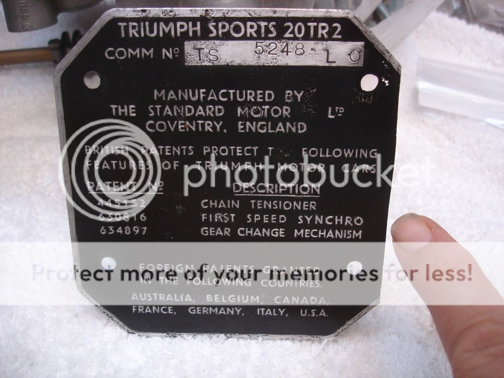
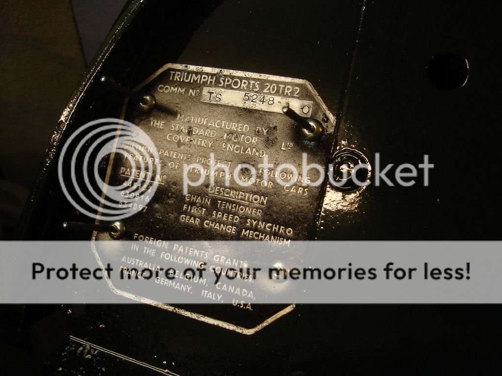
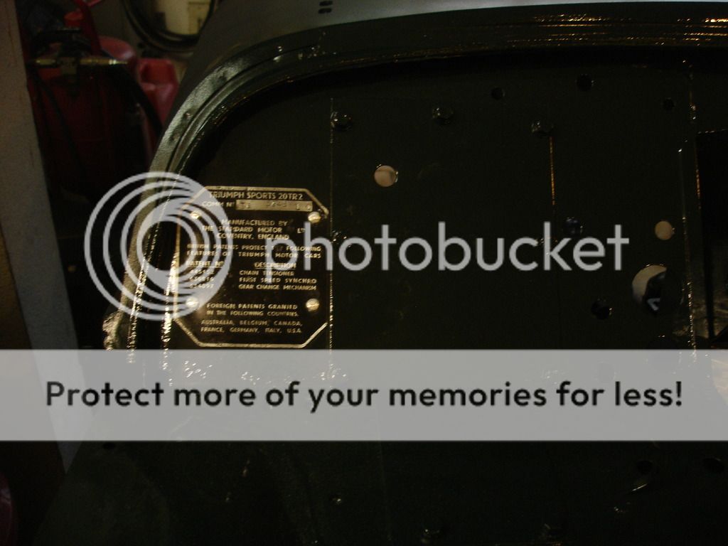
This bothered me for several years...the right edge of the commission was trimmed by hand. I initially thought this was some PO. Since then I have seen many, many pictures of the same trimming on other TR2's. I now firmly believe the factory did this to clear the RHD blanking plate. Another Standard MC quirk!?!


3/16" pop rivets. I am sure the perfect rivets are available...somewhere. I simply use standard large head rivets, but do not pull the rivet until the center breaks off. I only pull them until they are firmly held in place.


I then use a dremel cutoff disc to cut the center posts out. You would have to look very closely to tell any difference between these and the originals.


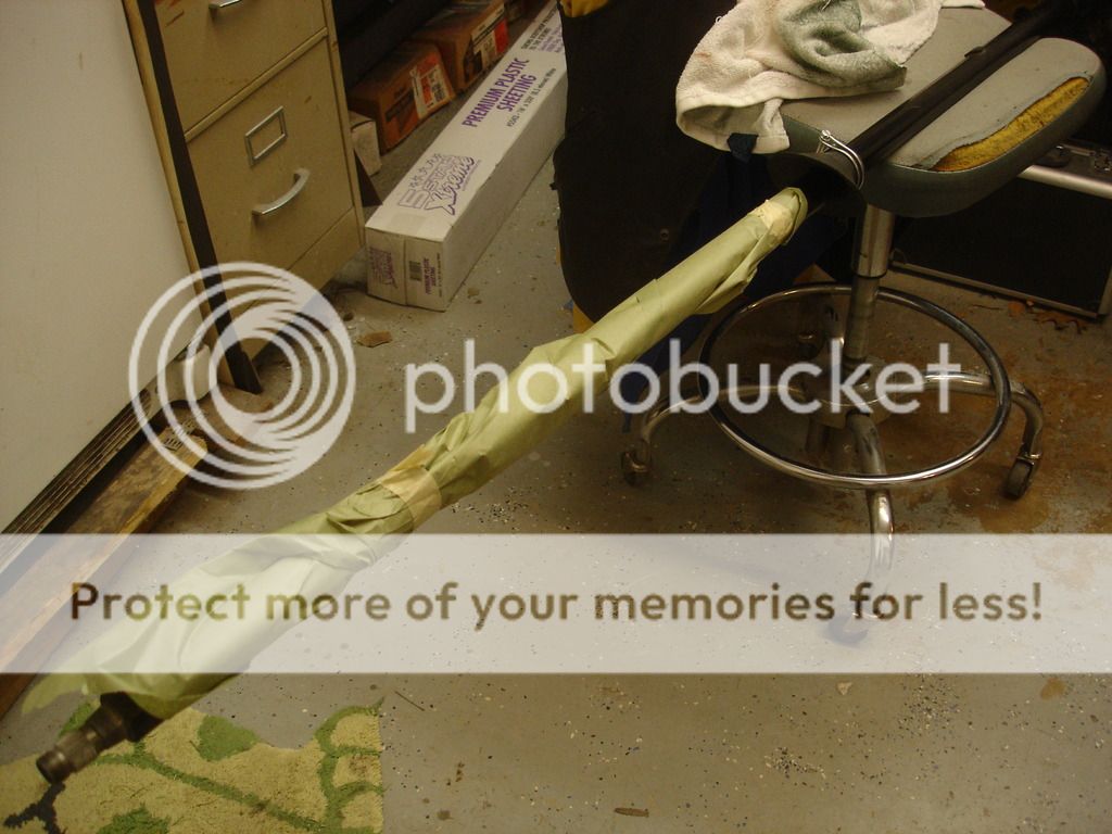
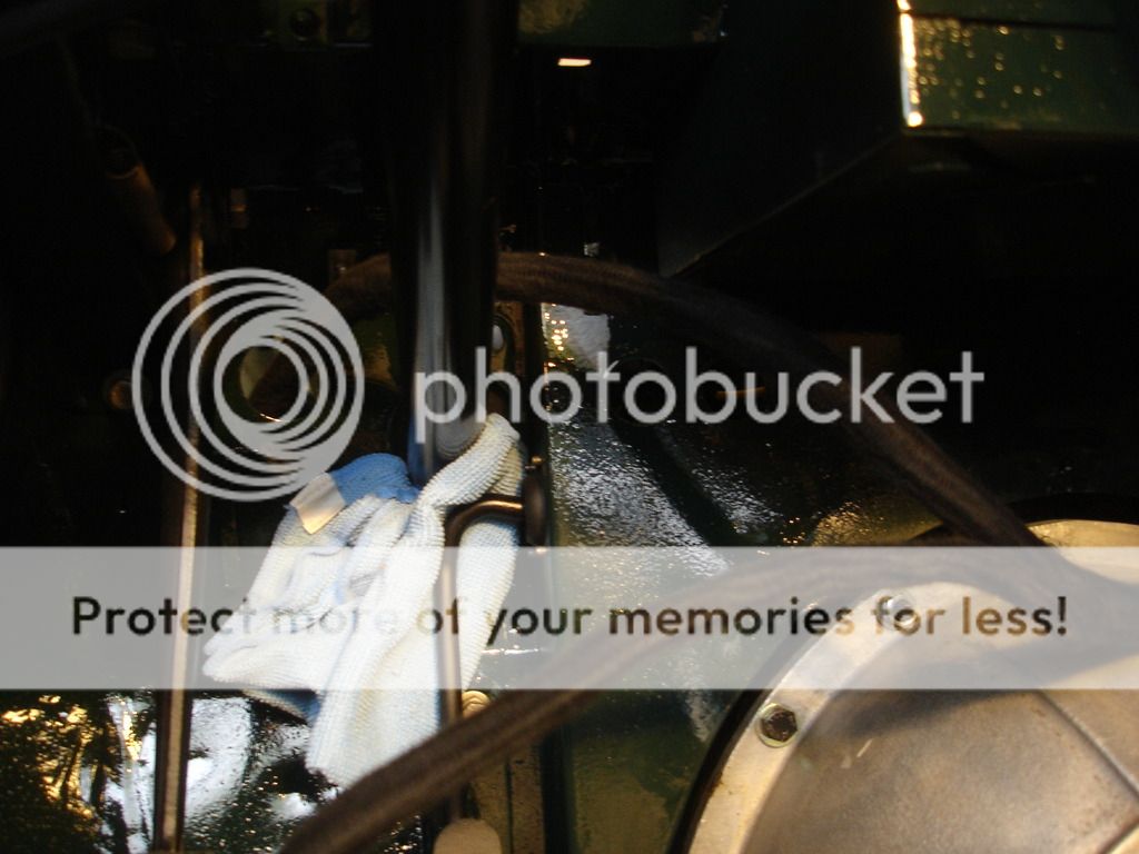
I am wrapping the top of the steering column so it will not get scratched while it slides through the firewall.


Do not forget to feed the sealing boot and clamp before running it through.


You may have figured out that there is a reason to the order of the last several parts. To save having to thread some lines/hoses, etc. in and around, you should intentionally install in this order, which is apparently the order the factory used:

1) Hard hydraulic lines.
2) Odd lines for speedo and tach.
3) Electrical harness.
4) Soft hoses.

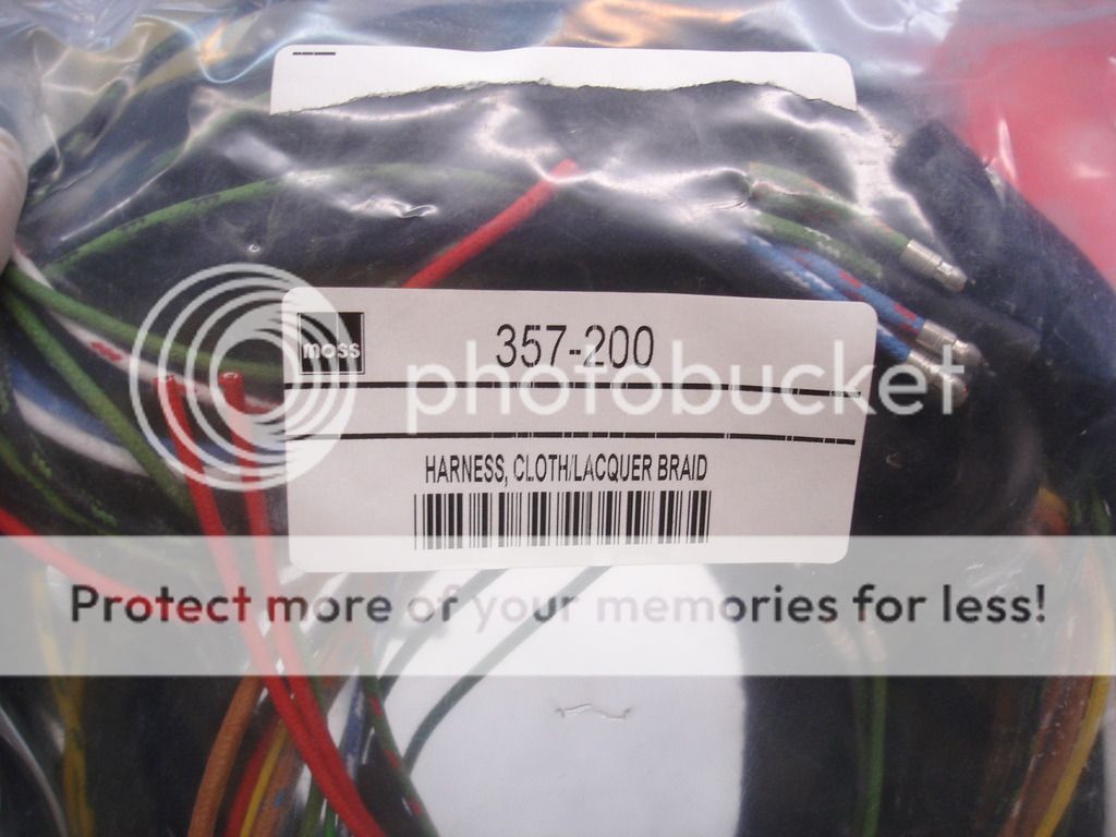
So, let's continue with the wiring harness.


Start in the cabin, and feed the largest bundle of free wires through from the cabin on the right side of the firewall. The Moss harness even has a grommet to help you locate this particular bundle.


In the cabin to the left of the passenger's feet. The harness splits into a thick bundle and a thin one. The thin is the tail light bundle, so it will separate and go to the right. The thick bundle goes left.


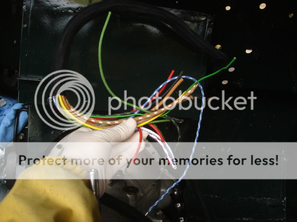
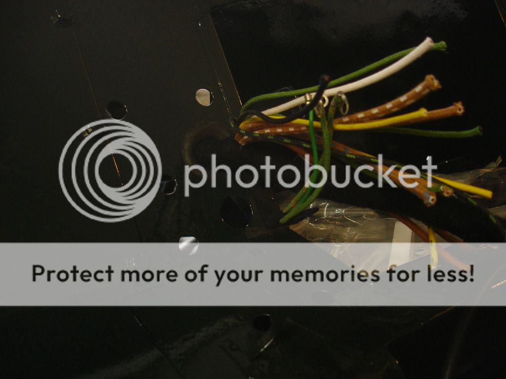
Next, the thick bundle splits again. The split with the wire fray goes to the front of the battery box and gets held with the body cable ties. This will feed all the instruments later.


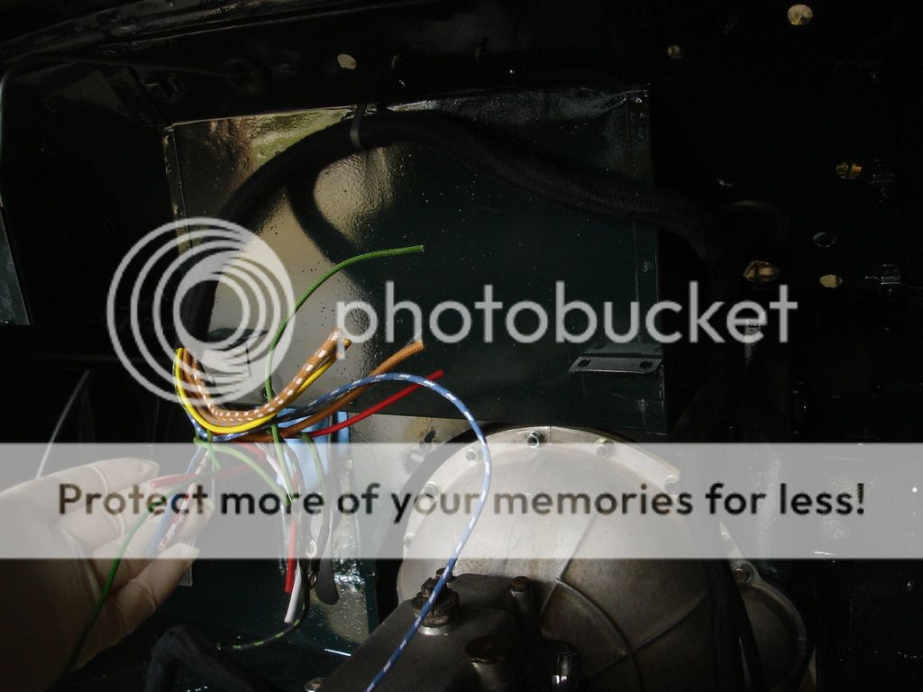
This is the long, thin bundle crossing the passenger's feet well to the right. The body has built in cable ties to hole it as it goes.


We tie it around all the way on the right side of the body and to the boot.

The green striped wire popping out in the last pic goes to the fuel tank sender.


And on around all the way to the tail lights.


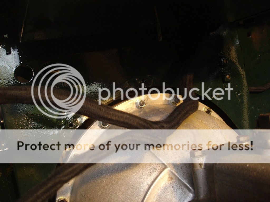
Now, the loose bundle gets stuffed forward of the battery box. It will be out of sight after it it is tied in place.


It goes over the steering column. Notice the column is padded with a rag at the firewall, since it is not held up by the dash...yet.


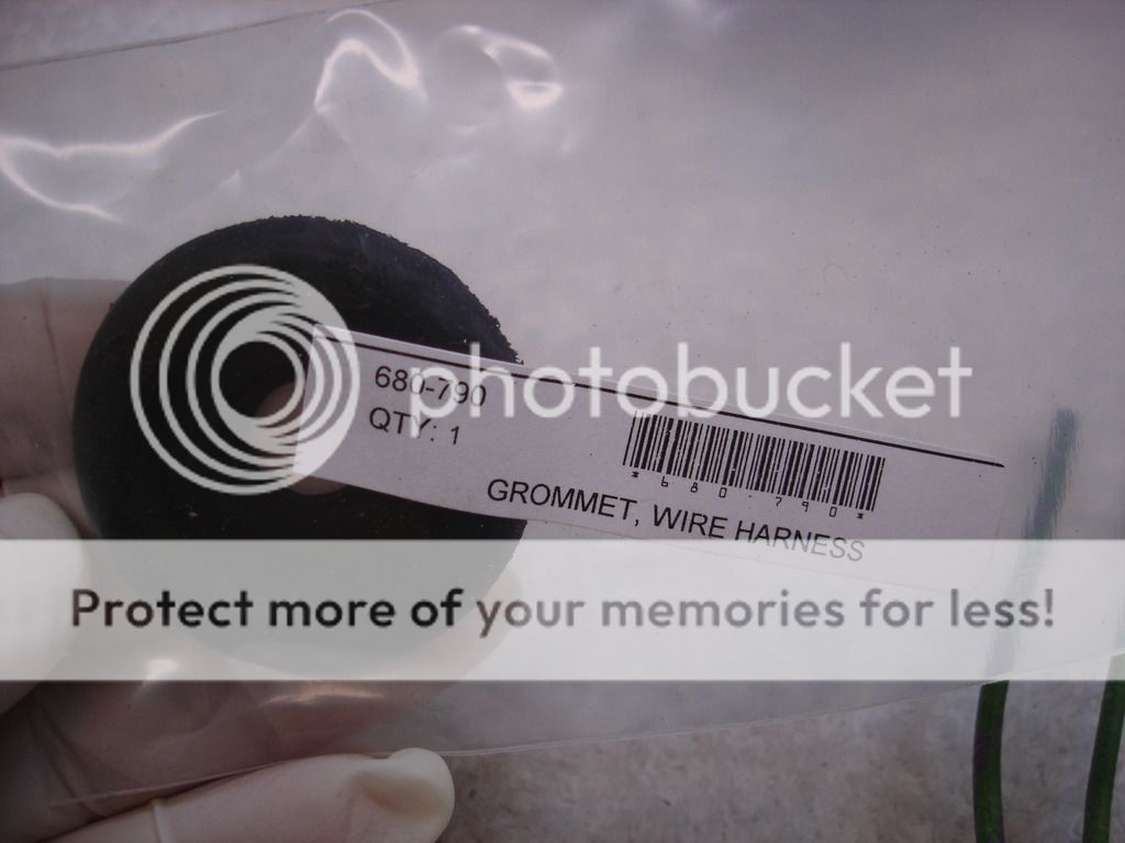
The bundle splits again. The long split goes back out the firewall. You will need to buy a grommet for this split.


The shorter split with the blue motif goes on around to the dimmer switch.


Don't forget to look for the provided cable ties on the body. Hmmm. If you remember in my body thread I pulled the ties up a bit before painting, so as to get paint all around them. I missed this one!! Bummer.


Now we can install the second firewall grommet.


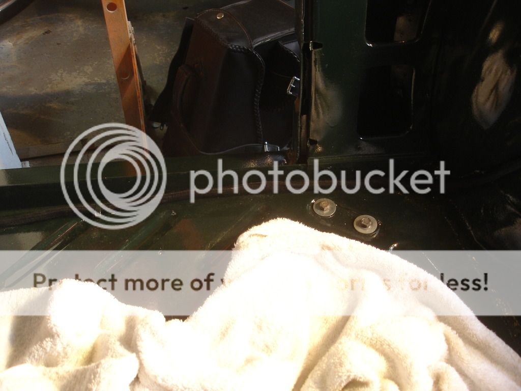
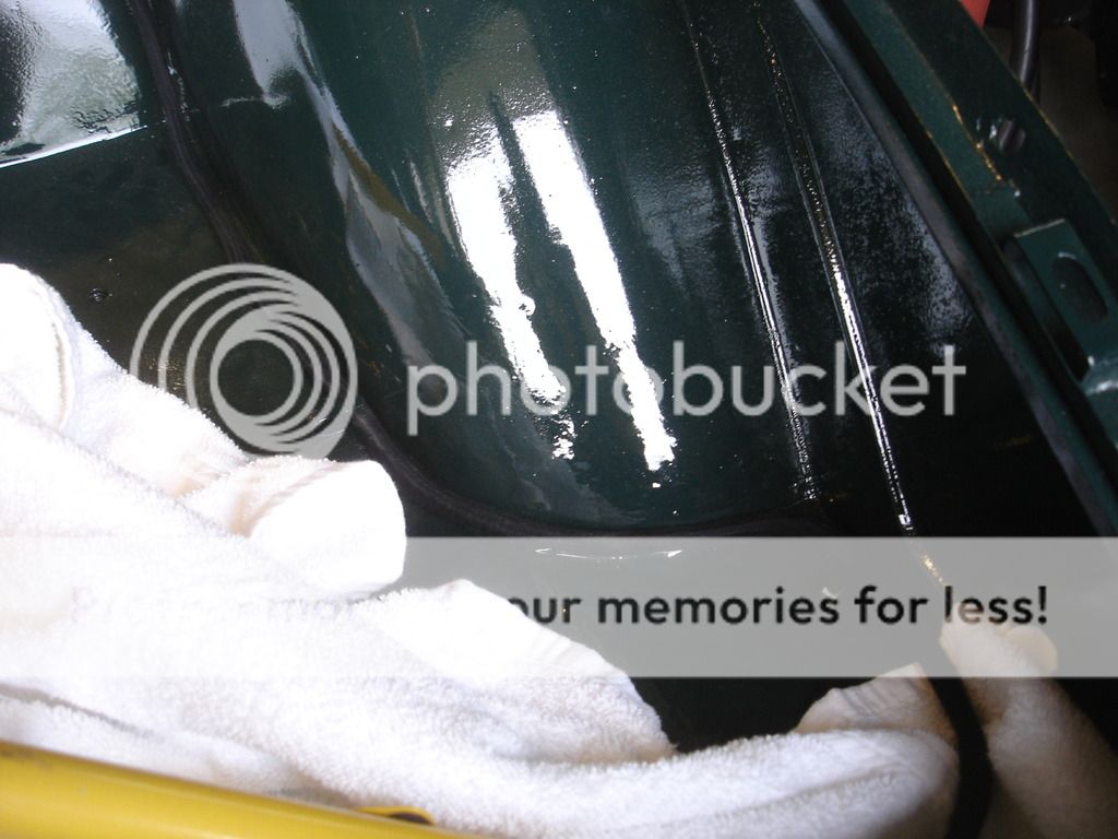
Once the grommet is installed, you continue in the left side engine bay, tying the final bundle around the inner wheel well.


The left ends here, at the horn mounting pad.


Back in the cabin, we have to tidy some of the runs. This is over the driver's right foot, where the dimmer bundles splits from the through-firewall bundle. You must spread them enough to have access to the heater through fitting later, when the heater hoses are installed.


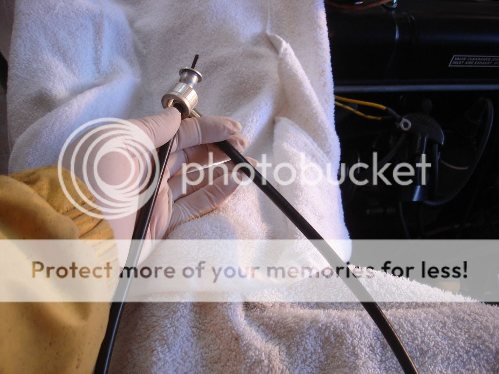
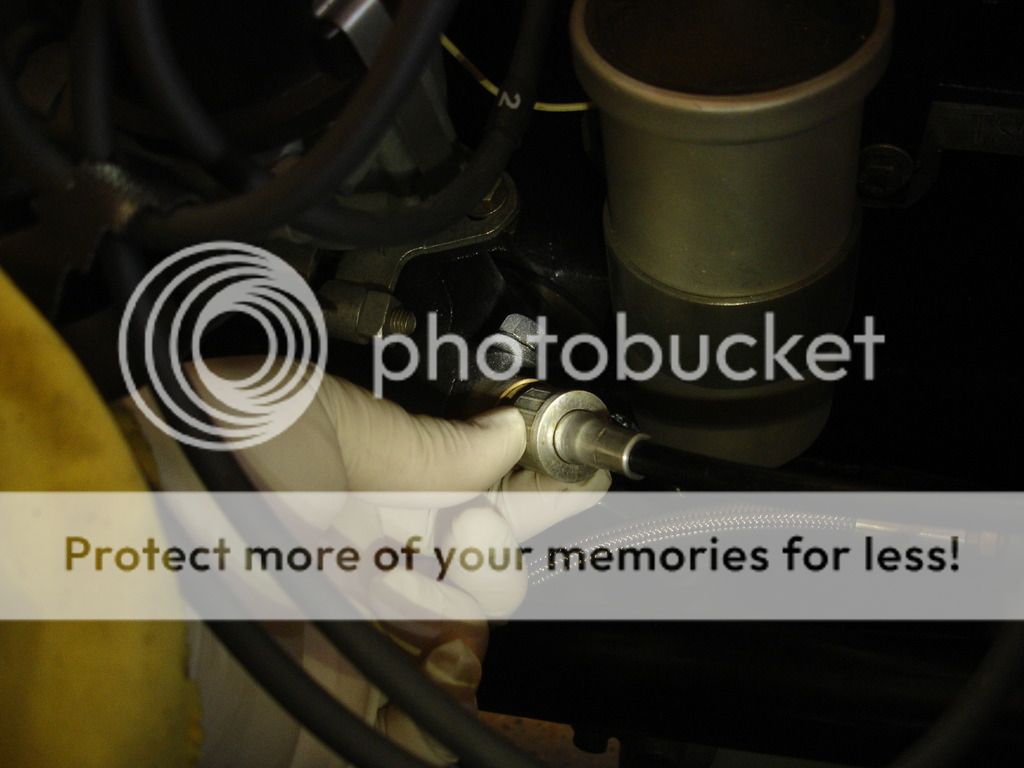
Found the tach cable!


It passes through the left side 1" hole behind the oil pressure flex hose, and uses a grommet. The other hole is for the temp sender capillary tube.


And the front is screwed to the distributor.
 
OP
CJD

CJD

Yoda
Country flag
Offline


Here is the fuse block installed.


Both the fuse block and voltage reg are held with these clip nuts that fit in 3/8" holes in the firewall.


Here is the "second" variation for the signal module.


I told you some of the items are in odd order. I realized I was putting pressure leaning on the radiator, so I went ahead and installed the support rods that tie the top of the radiator to the inner wings.


The overdrive solenoid mounts in the cabin to the lower right of the battery box. The screws are recessed in the battery box, so they do not contact the battery.


Starter solenoid. It is held with the same clip nuts shown earlier.


Once the wires can be routed properly around the fuse block, voltage reg, and solenoid, you can continue running the final bundle along the right inner wing liner.


The right side bundle ends at the horn mounting pad.


These bonnet dzeus brackets showed up in the box! What can I say...putting them on when they pop up keeps the bench clutter down.


Backing up...these wires go to the starter solenoid.


The TR2 uses screws to clamp bare wires to their components. That will work, but in my experience copper tends to creep over time, so the ends tend to loosen. I am tinning every wire with solder to minimize the tendency for the screws to loosen.


This is the wiring for the fuses and voltage reg.


On the left side of the engine, the lone white wire goes to the ignition coil.


At this point the wiring had to come to an end. I cannot install the dash until I get the material to cover it from Jonathon Skinner...so moving on to the spare tire well...


This is the vintage Michelin XZX 145mm installed. If I ever planned to drive the car in the rain I would not leave the towel in. I don't so the towel both protects the paint and helps remove the tire. Note: the wire wheel must fit with the outside downward.

That's it for another week. It's almost to the point I can consider it a car again. About 1 more day's work and it will be time to remount the body panels...and move the project back to the TR2 bodywork thread. Hooyah!
 

DavidApp

Yoda
Gold
Country flag
Offline
Hello John

Made great progress last week.
I will be referring to your photos when I get to the rebuild stage. I see where I need to add the cable tabs. Thank you.

Waiting for your seat recovering lesson. There was a great article on one of the vendors site but it seems to have gone now. Did not print it out at the time.

David
 
OP
CJD

CJD

Yoda
Country flag
Offline
Seat covering...that'll be fun!

I just learned something new, and rather interesting. I have been working on the fuel tank installation, and wondered how to ground the sending unit. The car came to me with an eyelet ground from a screw on the sender to who knows where, since the entire floor was gone. Then, it started to bother me that there was no ground wire provided in the new wiring harness. I mean, if they run a wire to the tank sender, and it also needs a ground, why not run the ground in the harness?

So I searched it, and got an answer from the Austin Healey Forum (although I didn't know it at the time).

Anyway...it seems the sender was originally grounded through the metal fuel line, which is in turn grounded to the fuel pump on the engine block via the stainless braided fuel hose. Half in disbelief, I just ran a tester over the hose and it's true...the braided hose grounds the tank!

So, no ground is needed unless you cut the line to add a filter, or you replace the braided hose with an all rubber hose. Who'd 'a thunk??
 

carpecursusII

Jedi Trainee
Country flag
Offline
I would put a separate ground on the sending unit. To ground the unit I run a wire from the unit to the bolt that holds the tank strap in the front.
 
OP
CJD

CJD

Yoda
Country flag
Offline
Thanks!

Just had my next setback. The steering wheel I've been planning to use for 4 years turns out to be a little under the weather after a closer look. I looked into buying new, and they are NLA across both sides of the pond. So....

I thought my woodworking was done on this project, but it appears I'll be restoring the original wheel to teak. Looks like possibly another "how to", or rather "how not to" thread?!?
 

DavidApp

Yoda
Gold
Country flag
Offline
The Roadster Factory must be out of stock. They list a repro. at a steep price but I have seen some crappy ones on e bay for nearly the same price. I got a deal on one on e bay. Just 2 small cracks and as the car came without one I had to do something. May look art the Roadster Factory one closer to drive day.

Will be watching for the wheel build thread.

David
 
OP
CJD

CJD

Yoda
Country flag
Offline
No, TRF still lists the steering wheels, but they do not have them. To quote ALbert they are "likely gone forever". Moss is NLA, Rimmer NLA, and Revington TR NLA...although they will rebuild yours for like $400. I did not check British Victoria, as they are listed at $499, and that makes teaking the old one a cheaper option.

On another good note...I have rounded up the correctly colored cloth wires and sheathing to assemble a period correct overdrive wiring harness. It was a bigger job than you would think. Many companies carry SOME cloth covered wiring...but none carry ALL the colors required. So I had to order from 4 different companies.

Now the only problem is I am back in Hawaii helping my daughter for the 3rd time in 6 weeks, so the project is on hold again. That's why I'm ordering all the odd clean-up parts.
 
Similar threads
Thread starter Title Forum Replies Date
M Recipe? Spridgets 11
G Recipe for disaster? Triumph 6
Nanhook TR2/3/3A TR2 shoes Triumph 2
CJD TR2/3/3A TR2 Annual Triumph 6
1955TR2 TR2/3/3A TR2/3 Oil Leak Where Oil Sending Pipe Connects to the Block Triumph 8
S TR2/3/3A WTB a tr2 original grill Triumph 0
S TR2/3/3A differential hubs early tr3 and tr2 Triumph 22
P TR2/3/3A TR2 Horn Mounts Triumph 7
S TR2/3/3A Tr2 and early tr3 differential. Triumph 10
mctriumph For Sale Tr2/3 scuttle mechanism Triumph Classifieds 7
S Wanted tr2 original grill Triumph Classifieds 10
J TR2/3/3A TR2 Fitting/mounting rear wing Triumph 11
A TR2 Transmission overhaul Restoration & Tools 0
D TR2/3/3A TR2 Flying Mile question Triumph 11
S TR2/3/3A tr2 muffler clamp Triumph 10
Southwarks TR2/3/3A TR2 door help! Triumph 2
G For Sale NEW PHOTOS: Triumph TR3 Chassis Frame + Front Suspension, Fits TR2,TR3,TR3A,TR3B Triumph Classifieds 1
P TR2/3/3A TR2 Headlight Trim Question: Triumph 8
A Wanted Girling Axle for TR2 Triumph Classifieds 5
J For Sale Triumph TR2 or TR3 elbow trim Triumph Classifieds 0
S TR2/3/3A tr2 and tr3 back trim above the back cover Triumph 0
KVH General Tech Heater and Vent Control Cables--TR2 thru TR4, and more . . . Triumph 3
S TR2/3/3A early tr3 and tr2 kick panels Triumph 3
S TR2/3/3A TR2 and early TR3 wipers Triumph 7
S TR2/3/3A tr2 Triumph 18
newmexTR3 For Sale TR2-4 performance valve springs, collars, exhaust seats, cotters Triumph Classifieds 0
J For Sale Triumph Tr2/3 seat foams Triumph Classifieds 1
J For Sale Triumph TR2, TR3, TR4 CAM SHAFT FOR SALE Triumph Classifieds 0
K For Sale TR2-TR4 Camshaft Sprockets...New...1/2 Price Triumph Classifieds 0
C TR2/3/3A TR2 Axle/wheel bearing removal Triumph 2
T For Sale TR2 - TR3 Gas Cap for sale Triumph Classifieds 1
71TR6 Set of 4 TR2/3/4 Connecting Rods Triumph Classifieds 0
P New member TR2 carpets Triumph 7
S TR2/3/3A Tr2 hood Triumph 8
W TR2/3/3A TR2 wiper motor mount Triumph 1
TRopic6 For Sale TR2/3 Brass Fuel Shutoff Tap [for parts] Triumph Classifieds 0
J For Sale Triumph TR2 TR3 TR3A New Moss Motors Black Karvel Style Carpet Kit Triumph Classifieds 0
S For Sale Triumph TR2/TR3/TR3A/TR3B Workshop on CCD/ROMManual – 1953 - 1962 Models Triumph Classifieds 0
Leatherman Wanted Red and black TR2 / 3 front emblem Triumph Classifieds 6
Jim_Stevens For Sale New TR2-3A inner sill assemblies Triumph Classifieds 3
C TR2/3/3A TR2 Chassis Clips Triumph 4
B For Sale TR2-3 Door Top Wood Rail Triumph Classifieds 1
T Wanted WTB TR2/TR3 Hood/Bonnet Latch Assembly with Prop Rod Triumph Classifieds 0
P TR2/3/3A TR2 color questions Triumph 23
C TR2/3/3A Triumph Tr2 Down Under Triumph 2
T TR2/3/3A About to strat a full restoration TR2 / TR3 ? Triumph 66
CJD TR2/3/3A TR2/3 Guru Final Exam Triumph 59
R TR2/3/3A TR2 Scam Triumph 13
SASSAMON Wanted WTB Early Sidescreens and mounting hardware for TR2/3 Triumph Classifieds 4
JFS TR2/3/3A TR2 Rear Plate Lite on TR3A Triumph 10

Similar threads

Top