• The Roadster Factory Recovery Fund - Friends, as you may have heard, The Roadster Factory, a respected British Car Parts business in PA, suffered a total loss in a fire on Christmas Day. Read about it, discuss or ask questions >> HERE. The Triumph Register of America is sponsoring a fund raiser to help TRF get back on their feet. If you can help, vist >> their GoFundMe page.
  • Hey there Guest!
    If you enjoy BCF and find our forum a useful resource, if you appreciate not having ads pop up all over the place and you want to ensure we can stay online - Please consider supporting with an "optional" low-cost annual subscription.
    **Upgrade Now**
    (PS: Subscribers don't see this UGLY banner)
Tips
Tips

TR2/3/3A Recipe for a TR2

OP
CJD

CJD

Yoda
Country flag
Offline


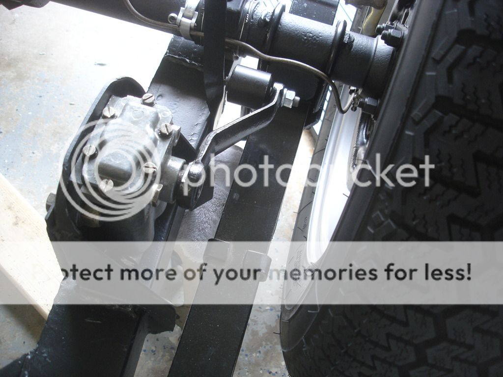
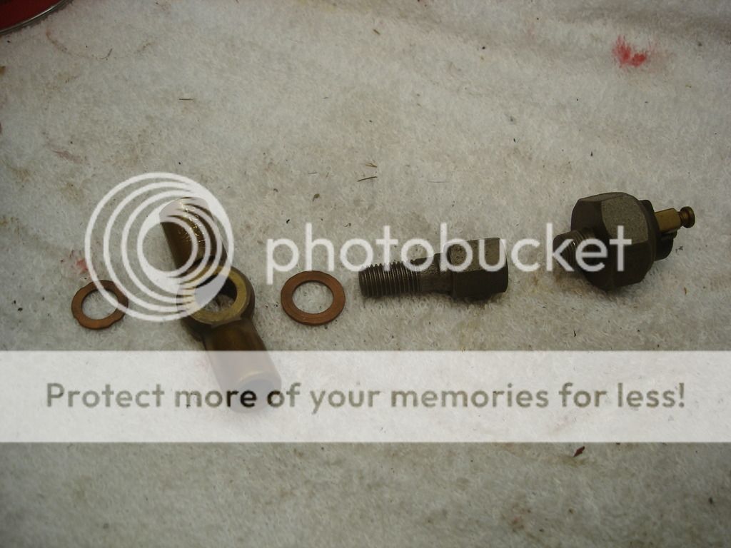
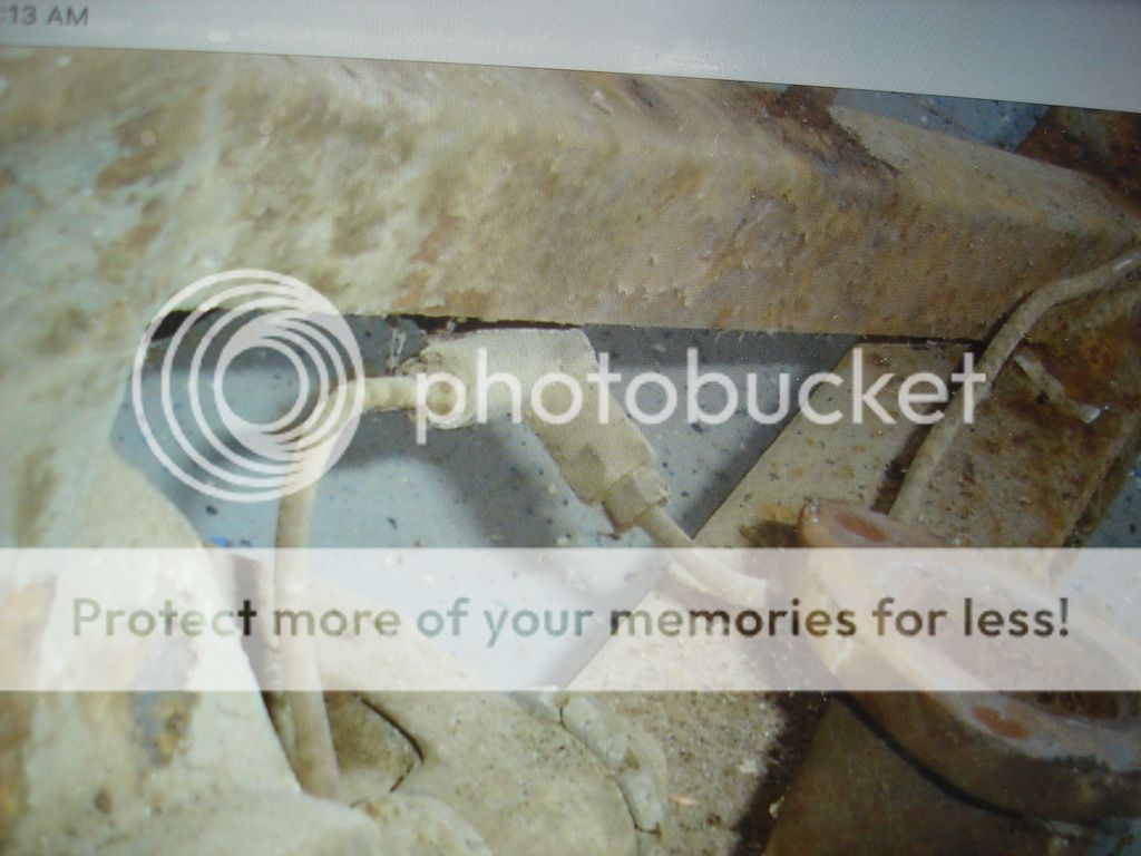
This odd little device is one of the 4 brake adjusters. What can I say, but, odd.

This brings up a point...the 2 cylinders with 2 adjusters up front leave a lot of possible issues with the TR2 brakes. You could lock up 2 cylinders (one left and one right) and still get brakes up front! You could also have a mechanic that thinks there is only one adjustment, and find your pedal goes to the floor even after he adjusts the brakes...


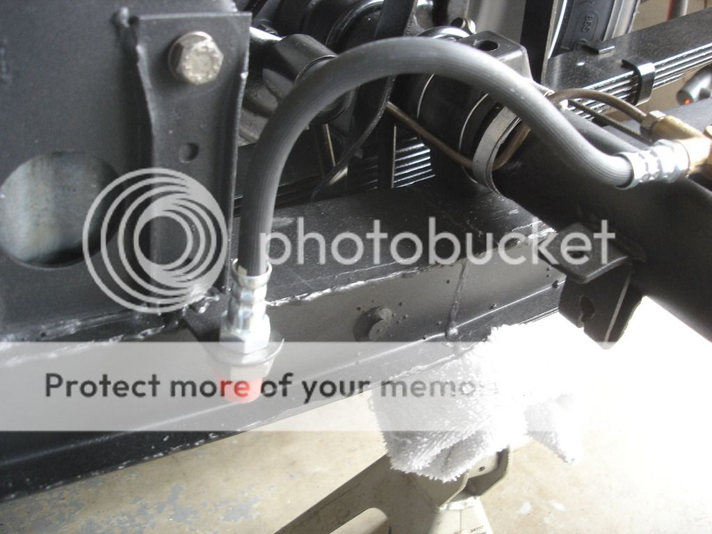
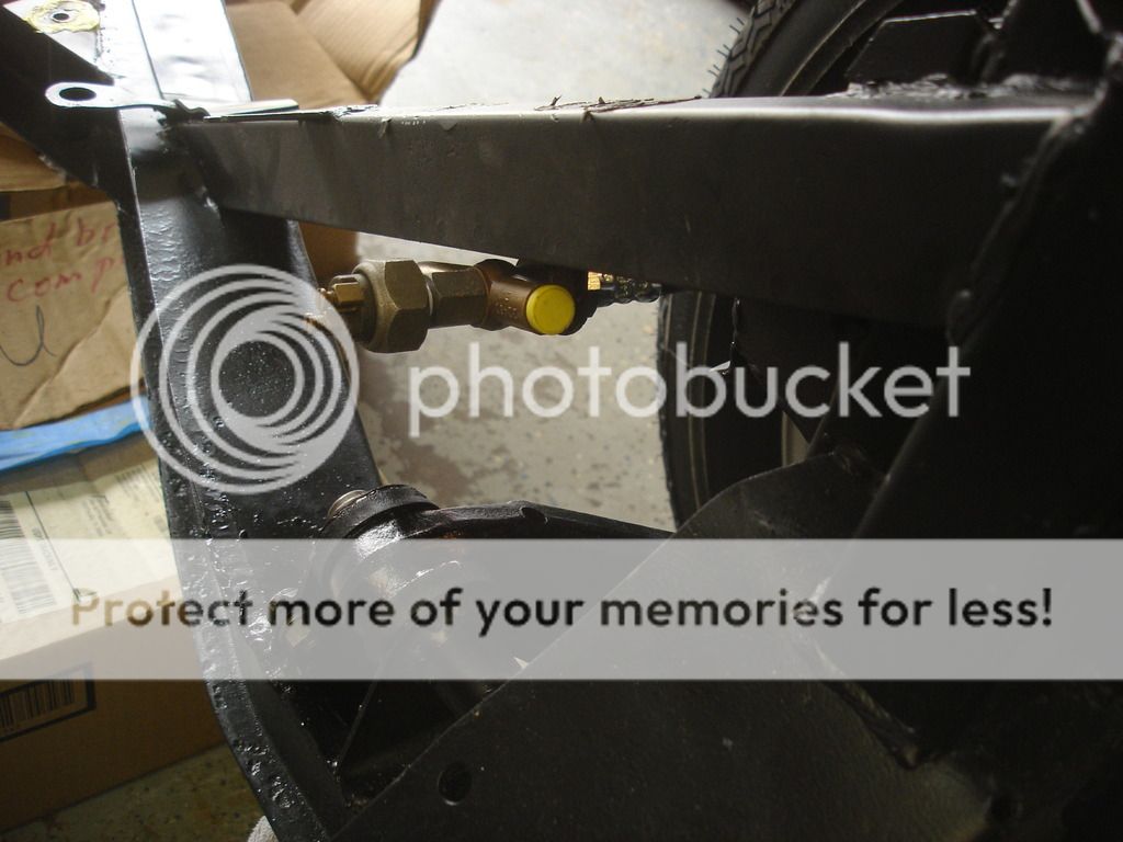
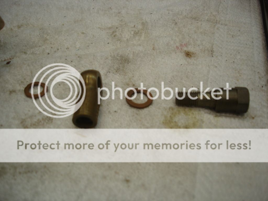
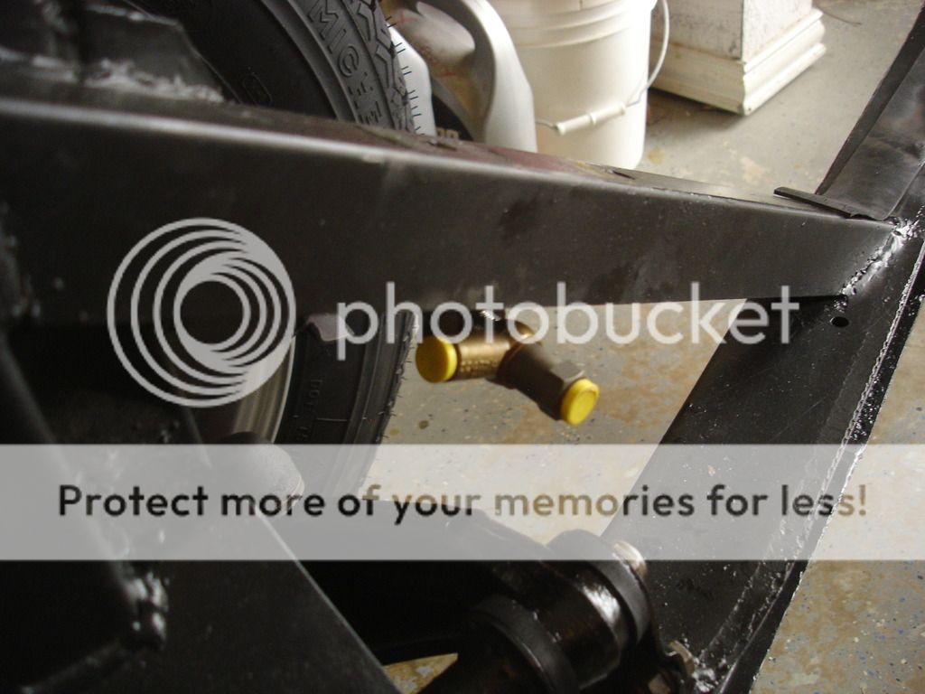
This is a grease catch. I guess they didn't trust the grease seal up front??


So, compared to single cylinder brakes, the TR2 brakes are a snap. Each shoe gets an adjuster, like so.


Now hang the springs down from a top shoe...rather a shoe you plan to use at the top, as they are all 4 the same.


And set the assembly resting on the 2 cylinders.


Then hook the bottom shoe to the springs...and push it into place. You're done! At this point the springs are pretty loose, until we adjust the play out with the adjusters.


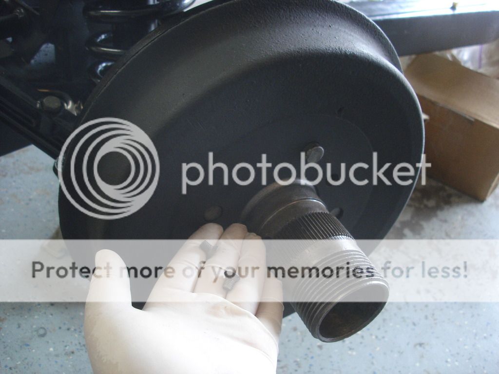
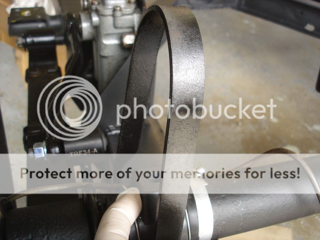
Another 60 year old new part!


Here's another unique part...the wire wheel TR2 front hub. Remember they have unique sides too! I forgot and had to do the first hub twice! RH threads go on the left side, and LH on the right. Very important.

I'll be quiet and let you follow along for the assembly...


OK...can't be quiet here. I've read many, many posts complaining about the felt seals being to thick. Nonsense. If you follow the instructions in the manual, the felt will comply and fit right in...just as it is supposed to.


Stop here for a second...this applies to all TR's!! If you read the manual, it tells you to torque the nut to 10 ftlbs. Notice I put a wheel on to do this. Straight from basic high school shop class...always rotate the bearing while you tighten it!! This does several things at once. Namely, it allows the bearings to seat without catching on any ridges, it allows the grease to displace so you don't get a false torque reading, AND...most importantly...it collapses the felt seal!!

The seal starts so tight that it makes it impossible to turn the hub while you are torquing the bearings to 10. Thus the need for the wheel. Of note...once I finished the process, I can hand spin the wheel and it will turn for 3 turns, no problem. The felt seal complies to the metal...as it was intended to do.


So, I turned the wheel, and the wrench, slowly...until I got the click.


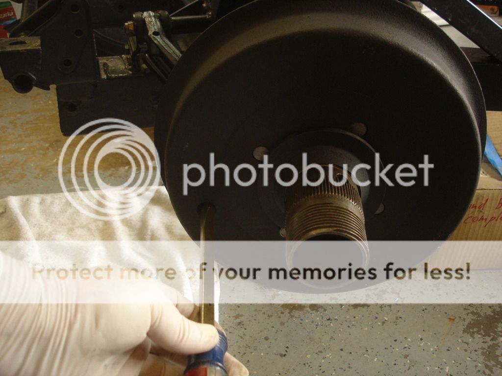
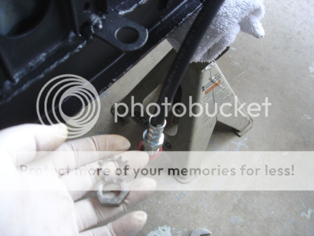
Once the torque is set, back off the nut 1-1/2 flat, and look for the cotter key hole through this little hole Triumph provided in the hub. Turn the nut up to another 1/2 flat until the holes line up.


Here I am holding the key in the nut with a large screw driver while I use a chisel to spread the key.


Notice I don't care that the key is not bent all the way over. Just open is enough, as the key does not turn and therefore has no force trying to sling it outward. Plus, when bent over getting it back out of this tight hub would be near impossible!

Gotta stop here, as I have to go to work...real work. I know. I hate it when real work gets in the way of fun work.

More soon.
 

BlueMax

Jedi Warrior
Offline
Replacing your brake tubing with new on a car that is that age is crucial. However, observations to the exterior of steel brake tubing buy no means will indicate its interior conditions unless you bore scope it or properly pressure test them? Why not install new tubing through out to insure the integrity to your braking system? BTW chassis is looking very nice.
 

M_Pied_Lourd

Darth Vader
Country flag
Offline
Interesting differences in the TR2!

Cheers
Tush
 

DavidApp

Yoda
Gold
Country flag
Offline
We called that front brake setup Twin Leading Shoe breaks as opposed to Leading and Trailing shoes for the rear brakes. Seem to remember they are wider than the rear brakes.

Would have benefited from your writeup when I did my front end.

David
 
OP
CJD

CJD

Yoda
Country flag
Offline
We called that front brake setup Twin Leading Shoe breaks as opposed to Leading and Trailing shoes for the rear brakes. Seem to remember they are wider than the rear brakes.

Would have benefited from your writeup when I did my front end.

David

They do look pretty big! I am having to psych myself up to be ready for the little shimmy that drum brake cars make when you apply the brakes initially and all the shoes tighten up. I have been spoiled by decades of disc brakes! I had never seen "twin leading shoe" before this...it's really simple in concept, but takes a lot of parts compared to discs.

Tush, it is amazing how much changed within 5 years of production. Your cars are MUCH better laid out! If you plan to actually "drive" your car, then the TR3A or B is the way to go. From the weaker diff to the all drums....the TR2 is more of a looker than a driver.
 

Tr3aguy

Jedi Knight
Country flag
Offline
Great it I ever get either of mine on the road I should be set. The TSF series should be the most advanced out of the two and more of the driver! I need to celebrate the small things John
 

DavidApp

Yoda
Gold
Country flag
Offline
Back in the late 1960s I was having my front brake shoes relined. Someone in the store asked what kind of truck they were off. Seem to remember they worked well.

David
 
OP
CJD

CJD

Yoda
Country flag
Offline
I have a few minutes, so here comes an update to the recipe...

DSC05688.jpg


DSC05689.jpg


Once the hubs are on and adjusted, we can add the brake drums. These 2 recessed screws hold the drums on...I suppose in case the wheels fall off and you still need brakes?!?

DSC05690.jpg


DSC05691.jpg


Now come the unobtanium wheel collars. If any of you ever buy integral hubs in the future, do NOT forget to check that these come with it!

DSC05692.jpg


This is a cool shot, showing how you access the front hub cotter key hole. The axle, bearing adjusting nut, and hub must be lined up...and then you get to fidget getting the key in that tiny hole through the small holes. Fun!

DSC05693.jpg


The final step is to adjust the brakes. Turn the drum so one of the adjusters lines up with the hole in the drum. Then reach in with a flat blade screwdriver and turn the adjuster all the way clockwise. Once it won't turn any more, then back off CCW one click. Don't forget to rotate the drum 180 degrees and do it again...
 
OP
CJD

CJD

Yoda
Country flag
Offline
Now we'll back up and see where we are so far...

DSC05694.jpg


DSC05695.jpg


DSC05696.jpg


DSC05697.jpg


DSC05698.jpg


These last 2 pics deserve a note...

You must make sure that the bump stops that are tied to the axle line up with the EDGE of the frame on the bottom and with the rebound strap on the top. You do not want it to line up with the middle of the frame, as the 16 gage frame will dent in the middle from continuously getting rapped by the axle in rebound. The edge of the frame will take the punishment, though.

I had to remove the straps and move the bumps stops over just a tad...continuing on...

DSC05699.jpg


DSC05700.jpg


DSC05701.jpg


Cleaning up the brake hoses here. They are held to the frame tabs with these big nuts and star lock washers.

DSC05702.jpg


As I move on to the brake lines...this is me testing the brake light switch. The switch is the original. For all I know it is THE original. So, to test it I simply fired up the multi-tester in Ohm mode and then blew compressed air into the switch. When air was added the contacts closed perfectly. I love it when I get to keep the original parts!

DSC05704.jpg


The brake light switch on the TR2 is on the left hand side of the car. These are the parts that screw right into the hose end we just located on the frame. Interesting set up, to say the least!?!

DSC05705.jpg


Here I absolutely could not remember what it looked like 4 years ago...Digital photography is a Boone to restoration work! Never scrimp with the pics when you disect your project.

DSC05706.jpg


Here it is reassembled on the frame. Looks a bit different now!?!

DSC05707.jpg


This is the Rube Goldberg set-up on the right side.

DSC05708.jpg


Before...

DSC05709.jpg


And after. Almost??

At this point I am ready to fabricate the steel brake lines that I was not comfortable re-using. This also started a saga in trying to find the "B" nuts to fit to the new 3/16" steel lines. Several of the nuts were ruined in the tear-down. They have to be replaced. Here's how it went down...

1). First I took one used B nut to O'Reilly's to match. I had to by 4 short lengths of pre-fab lines that had B nuts. I now know that my eyesight is failing, as the nuts looked like a match at the store...but when I tried to insert them on the car...they were 3/8"x24 pitch. It turns out the original nuts are 3/8" x 20 pitch. Bummer!

2). I figured I didn't want to mess around with them, so I drove across Fort Worth to a specialty hydraulic shop that caries everything hydraulic. They had one. ONE!! Are you kidding me?? They could order more, BUT, their nut was 3/16" shorter than the TR2 nut. Couldn't tell at the time if it would be long enough or not. You guessed it...NOT!! Like many Triumph fittings, namely the inlet line to the fuel pump, the fitting is a standard size, but Triumph fittings are deeper recessed. Double Bummer!

3). I drove to NAPA, Advance Auto, Auto Zone, and a couple local parts stores looking for the nuts. No luck.

4). Finally I had a brainstorm...the parts shed! Yeah, that's the ticket! I figured I have one more Lockheed rear end and several spare disc brake calipers...surely they will have B nuts I can cannibalize. So, back to the house, grab the keys to the shed, back to the shed and started digging.

So, Marv's diff did not come with the brake lines. Strike one. I pulled out the disc brake calipers. Turns out the disc brakes changed the fittings to the later style 3/8" x 24 pitch. Ugh...strike 2! I began digging through every box, every bag, every crevice in the shed. Finally. I found a pair of front brake cylinder tie lines that had the correct B nuts. WHeew! I was almost out for the count.

Well, I got the nuts home, removed from the old lines and bead blasted. 6 hours down the drain. I am now exactly where I THOUGHT I was the day before, namely, ready to fab the chassis steel lines that need to go in before the engine can be dropped in place.

That's all I have time for right now. I'm really down to 1 good day's work and the body can come out of the Living room. Amazing how fast this can go with all the prep work finished.

But...for everyone else...don't throw away those blasted B nuts!
 
OP
CJD

CJD

Yoda
Country flag
Offline
No update this week. More family to take care of...this time Hilo. Hope to be back at it by middle of next week.
 
OP
CJD

CJD

Yoda
Country flag
Offline
Back on the Job...

If you remember from the last update, I had a bear of a time trying to find the "inverted flare nuts" for the new brake lines. That is not the term I used last update...but I have since learned that inverted flare nut IS, indeed, the proper term. Well, the issue came back to bite me after the 3 weeks off. To recap:

I bought the nuts from O'Reilly's, only to find that the modern standard is 3/8"x24 pitch. The old Triumph parts are 3/8"x20BSF pitch. I drove all over the 2 city area, only to give up. I then ransacked my storage facility and found some of the nuts on old TR2 brake slave cylinders. I thought I had the issue licked...but no such luck.

After building the first new brake line, it would NOT fit the car!! It turns out the slave cylinders I had also used the modern 24 pitch! Ugh! I did get a lot of practice in flaring brake lines for no good result. After spending hours searching the web, I have found a single supplier of the 3/8"x20bsf inverted flare nuts...that are ALSO the 1" length needed. I am waiting for them to arrive. In the mean time...


Here is my first flare, and the (at the time) wrong size nut! I am showing the nifty bending tool I bought for $10. The tool is alright, but this tubing is so flexible that you can get decent bends by hand without the tool.


This is the finished line that runs under the engine block along the rear of the front crossmember. It ties the front brakes together.

Since that piece was made with the wrong nuts...it'll have to sit until I get the correct nuts to rebuild it. Bummer. In the mean time, I was able to salvage enough of the original nuts to continue with other brake lines...


This is the original front to rear line, laid out next to the NEW line.


Before installing the lines, the "X" members get new grommets where the brake lines pass through.


The rear gets threaded first, and the line pushed all the way rearward, so the front of the line can be passed through it's grommet without bending the line.


The rear gets connected, and we follow along to the front, making sure the line rides out of the way of other frame parts, like the rear spring bolts. Now we need these nifty line clips to hold the line against the inside of the frame members.


Note a clip at each end of the little detour the line takes around the jack mount.


The last clip is on the top of the frame at the 45 degree spring tower brace.


And the first work in 3 weeks is done! Hip, hip...
 
Last edited:
OP
CJD

CJD

Yoda
Country flag
Offline


Next is the fuel line that runs down the left side of the frame. The original was in good shape, so it got cleaned and sprayed with cold galvanizing paint.


The ends have the usual olive nuts that Triumph seems to love so much!


Camera never focused on this one. This is looking upward from under the frame. The fuel line starts here, clipped to the bottom of the rear outrigger tube. Note that the olive nut here provides a way of disconnecting the fuel tank line from the main line.


Same area from above.


Now we continue forward, adding the same clips we used for the brake line on the other side.


This little bump allows access to the exhaust pipe mounting bolt...later...


And here we leave off where the (in)famous fuel shutoff will be mounted.


From the deep dark bowels of the garage emerges the motor not seen for almost 3 years hence!!


I kind'a erk myself sometimes. I can't remember at this stage what parts I have or have not purchased. Fortunately, old me looked after current me...most of the time. Under the first layer of trash bags were the little odds to mount the flywheel, clutch, and temperature gage capillary tube.


OP
CJD

CJD

Yoda
Country flag
Offline
After a brief pause...while I retrieved the hoist from the shed...


She flies again!!


Now, since there is only a front mount for the motor with no tranny, it's time to position a jack with a wood pad to hold the rear of the engine.


As the motor comes down into place, first the left front mounting bolt goes in...


Followed by the rear left bolt...which includes the motor to frame grounding strap.


The engine settles gently at the rear onto our jack pad. And then the right mounting bolts were installed.


Important safety tip!!

The tranny input shaft pilot bearing MUST be installed before mounting the flywheel and tranny. In my younger years I pulled trannies unnecessarily when nobody on the crew could admit to installing this bearing. Double and triple check! Or just take a pic like I just did!?!

Note: I have now dealt with 4 TR2/3 cranks with many more pilot bearings. In American cars these bearings are press fit into the crank. I have yet to have one into our TR's that is a tight fit. I have decided that the crank is machined for a slip fit. Don't know why...but it works and that's all I know after searching many supply stores for a tight bearing.

Before installing, be sure to use a bit of grease inside and out. Not too much, or it will sling out onto the clutch disc and cause chatter later.


Many...many...moons ago this flywheel was saved from the scrap yard. At some point in it's life the mounting bolts came loose and the wheel wallowed on the crank. I can only imagine the racket it was making as some no-mind pulled it into his mechanic complaining about a strange noise!?!


In another post I went into the details of drilling the new locating hole off 90 degrees and opening up the mounting bolt holes to 7/16". Of course the crank flange had to be machined for the larger bolts too. Runnout on the face of the wheel was checked...and in the end it should be stronger now than when it left the factory. At least that's my story and I'm sticking to it!


Here is the crank flange showing the locating pin for the flywheel. The manual mentions moving the pin 180 degrees to account for starter ring gear wear. I had to account for loose flywheel mounting wear instead.


TR2's use the early "pressed on" ring gear, to match the early "bullet nosed" starter.


Here's one of my super heavy duty 7/16" bolts. It will go on without washers and with locktite. I normally do not use locktite on assembly, but this wheel has already shown a desire to come off!


These new bolts go in at 60ft/lbs. Here is how I hold the crank from turning while I torque the bolts...just a big screwdriver through the starter hole on the block.


The clutch disc has a raised center. The raised center will hit the flywheel bolts if installed forward. So...the raised center MUST FACE REAR.


This is the flat side that goes toward the engine.


Of course, clean the flywheel face thoroughly with carb or brake cleaner to remove the packing grease. Also notice that this disc looks decent. Those rivets have to hold together at 5k rpm or more. I have seen rivets with washers and other junk that I know would come apart in use. Look it over t make sure it looks like a quality part instead of junk from China or Mexico.


Here is the disc setting on the clutch pressure plate. Also clean the grease off the clutch before assembly.


Now, the disc and clutch go on the flywheel. Notice that my assembly is marked. They were balanced, so must be assembled as they were balanced.
 
OP
CJD

CJD

Yoda
Country flag
Offline
Note about balancing:

The easiest way for a shop to balance your engine is to take all the parts and put them together...then spin it and balance it as a unit. That works. BUT! If you think about it, if you ever have to replace a clutch or flywheel or such, then the resulting assembly may be out of balance. It is not practical to take your engine apart to replace a clutch!

I give my shop specific directions to balance the crank alone. Then add the flywheel and balance the wheel on the crank. THEN add the clutch. I have to pay extra, but the end result is that every part is balanced with itself. As long as the new clutch is balanced...then my resultant assembly will also be balanced.

I still put it all together using my marks...just to be absolutely sure! I check all machine work when I get it back. I never trust a shop completely, as every tech has a bad day. Unfortunately balancing work can only be checked after the engine is run.


Spare tranny input shaft. I know...most don't have these laying around. In fact it bothers me more that I DO have one just laying around than it should bother you that you don't! I need to get a life!?!


If you have a shaft, insert it now, before tightening the clutch bolts. If you have the cheap plastic alignment tool, use that. Any parts house sells generic tools...and they work too. I have even reached a point that I can actually eyeball that the clutch disc is centered. (another skill I am not necessarily proud of!?!) Anyway, this sounds simple, but you can still get the disc off if not done correctly. Here's how it works:

Do not just jam the tool in and let the disc hang on the tool while you tighten the bolts. If you play with the tool (OK you guys...trying to teach here!) you'll find it has play left, right, up and down. First average the left and right, so the tool is centered laterally. Now, lift up and see how high it will go. Lower it about half that distance and hold it right there...centered left and right...centered up and down. You must hold it, or the disc will pull it back down. Now tighten the bolts to snug before releasing the tool. ( I better move on fast before I get in trouble)


Now, once the disc is held and bolts all snugged...start at one and turn it about 1/2 turn tighter. Move to the next around the wheel and give it the exact same amount...continue this in order until the bolts are all tight. Finish by torquing them to 20ft/lbs.


Tah dah!
 
Last edited:
OP
CJD

CJD

Yoda
Country flag
Offline


Here's an old blast from the past. The tarred up, sludged up OD tranny from 2-1/2 years ago! Time to put her back in.


Here is another opportunity to have to take everything back apart if you don't pay attention. Make sure the throw out bearing is in place!! Also last chance to make sure all the bolts are wired/torqued. You want a bit of oil on the throwout bearing face. Just a bit! Also a smear on the tranny snout wear the bearing slides. Finally a smear on the input splines.

Note: If I forgot to grease these parts I would not even think about opening back up to do it. This area gets oil from the rear crank seal. Too much is FAR worse than no grease. Too much will fly into the clutch disc, burn on the flywheel and pressure plates when they heat up...and then the clutch will start to chatter. Once chattering starts the only repair is to replace the disc and face the plates. Better to not use too much grease!!

As shown in the pic, the nose of the shaft that goes into the pilot bearing has WAY too much.


Put the tranny in 4th gear for the installation. You need to align the splines on the disc and tranny, so you must have the most leverage possible to turn the input shaft while aligning. You can then spin the output flange to turn the input shaft easily.


Now this makes it look easy. I actually tried to put this in alone, but gave up. It is difficult to align, turn the flange, and lift alone. I admitted defeat and yelled for my son to help. With my son it took at least 5 seconds! One time a helper is indispensable.


I tell you...NOTHING on this restoration was easy. If you remember, this is the tranny rear mounting plate I had to patch back together. Even this simple part caused me grief! But, that's all over. After the years of prep, now these difficult parts just fall into place.


And that's where I will leave off for this week.
 

M_Pied_Lourd

Darth Vader
Country flag
Offline
Beautiful.

Cheers
Tush
 

mgedit

Jedi Knight
Country flag
Offline
Great work. Brings back many memories, especially trying to get the brake lines sorted out. My TR3 is very TR2 like.

Cheers, Mike
 
Similar threads
Thread starter Title Forum Replies Date
M Recipe? Spridgets 11
G Recipe for disaster? Triumph 6
Nanhook TR2/3/3A TR2 shoes Triumph 2
CJD TR2/3/3A TR2 Annual Triumph 6
1955TR2 TR2/3/3A TR2/3 Oil Leak Where Oil Sending Pipe Connects to the Block Triumph 8
S TR2/3/3A WTB a tr2 original grill Triumph 0
S TR2/3/3A differential hubs early tr3 and tr2 Triumph 22
P TR2/3/3A TR2 Horn Mounts Triumph 7
S TR2/3/3A Tr2 and early tr3 differential. Triumph 10
mctriumph For Sale Tr2/3 scuttle mechanism Triumph Classifieds 7
S Wanted tr2 original grill Triumph Classifieds 10
J TR2/3/3A TR2 Fitting/mounting rear wing Triumph 11
A TR2 Transmission overhaul Restoration & Tools 0
D TR2/3/3A TR2 Flying Mile question Triumph 11
S TR2/3/3A tr2 muffler clamp Triumph 10
Southwarks TR2/3/3A TR2 door help! Triumph 2
G For Sale NEW PHOTOS: Triumph TR3 Chassis Frame + Front Suspension, Fits TR2,TR3,TR3A,TR3B Triumph Classifieds 1
P TR2/3/3A TR2 Headlight Trim Question: Triumph 8
A Wanted Girling Axle for TR2 Triumph Classifieds 5
J For Sale Triumph TR2 or TR3 elbow trim Triumph Classifieds 0
S TR2/3/3A tr2 and tr3 back trim above the back cover Triumph 0
KVH General Tech Heater and Vent Control Cables--TR2 thru TR4, and more . . . Triumph 3
S TR2/3/3A early tr3 and tr2 kick panels Triumph 3
S TR2/3/3A TR2 and early TR3 wipers Triumph 7
S TR2/3/3A tr2 Triumph 18
newmexTR3 For Sale TR2-4 performance valve springs, collars, exhaust seats, cotters Triumph Classifieds 0
J For Sale Triumph Tr2/3 seat foams Triumph Classifieds 1
J For Sale Triumph TR2, TR3, TR4 CAM SHAFT FOR SALE Triumph Classifieds 0
K For Sale TR2-TR4 Camshaft Sprockets...New...1/2 Price Triumph Classifieds 0
C TR2/3/3A TR2 Axle/wheel bearing removal Triumph 2
T For Sale TR2 - TR3 Gas Cap for sale Triumph Classifieds 1
71TR6 Set of 4 TR2/3/4 Connecting Rods Triumph Classifieds 0
P New member TR2 carpets Triumph 7
S TR2/3/3A Tr2 hood Triumph 8
W TR2/3/3A TR2 wiper motor mount Triumph 1
TRopic6 For Sale TR2/3 Brass Fuel Shutoff Tap [for parts] Triumph Classifieds 0
J For Sale Triumph TR2 TR3 TR3A New Moss Motors Black Karvel Style Carpet Kit Triumph Classifieds 0
S For Sale Triumph TR2/TR3/TR3A/TR3B Workshop on CCD/ROMManual – 1953 - 1962 Models Triumph Classifieds 0
Leatherman Wanted Red and black TR2 / 3 front emblem Triumph Classifieds 6
Jim_Stevens For Sale New TR2-3A inner sill assemblies Triumph Classifieds 3
C TR2/3/3A TR2 Chassis Clips Triumph 4
B For Sale TR2-3 Door Top Wood Rail Triumph Classifieds 1
T Wanted WTB TR2/TR3 Hood/Bonnet Latch Assembly with Prop Rod Triumph Classifieds 0
P TR2/3/3A TR2 color questions Triumph 23
C TR2/3/3A Triumph Tr2 Down Under Triumph 2
T TR2/3/3A About to strat a full restoration TR2 / TR3 ? Triumph 66
CJD TR2/3/3A TR2/3 Guru Final Exam Triumph 59
R TR2/3/3A TR2 Scam Triumph 13
SASSAMON Wanted WTB Early Sidescreens and mounting hardware for TR2/3 Triumph Classifieds 4
JFS TR2/3/3A TR2 Rear Plate Lite on TR3A Triumph 10

Similar threads

Top