• The Roadster Factory Recovery Fund - Friends, as you may have heard, The Roadster Factory, a respected British Car Parts business in PA, suffered a total loss in a fire on Christmas Day. Read about it, discuss or ask questions >> HERE. The Triumph Register of America is sponsoring a fund raiser to help TRF get back on their feet. If you can help, vist >> their GoFundMe page.
  • Hey there Guest!
    If you enjoy BCF and find our forum a useful resource, if you appreciate not having ads pop up all over the place and you want to ensure we can stay online - Please consider supporting with an "optional" low-cost annual subscription.
    **Upgrade Now**
    (PS: Subscribers don't see this UGLY banner)
Tips
Tips

Removing BJ8 'Adjustable' Steering Wheel Hub

pkmh

Jedi Warrior
Country flag
Offline
Again, I say hello for my next challenge awaits me as follows on my BJ8…

Today, I was successful in part anyway, in removing my ‘adjustable type’ Steering Control Head assembly from the driver side interior.

FWIW, there are a number of reasons why I want to do this, besides just becoming familiar and performing some first time inspection and required cleaning.

A. Signals fail to work, even after replacing a total of two new flasher units (short burning them out) and installing the appropriate type signal bulbs. So naturally, I want to inspect the mechanics and wiring setup as well as clean and refurbish all pieces and to see if there is an existing short in this area;

B. I want to remove my existing steering wheel so I can preserve and restore by first strengthening the third points with welded metal plus restore the fractured plastic at these third points. After making some mockups of a composition consisting of pulverized old records (78’s) and mixing with a high strength glue (in lieu of epoxies and admixtures I‘ve been made aware of), the results are a very economical, no residue, solid black finish and which can be further grinded and polished. This is my choice and I will keep all posted, especially its behavior in extreme heat and cold weather.

Back to the issue at hand...

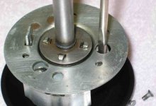
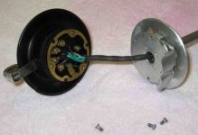
So far, my success has been limited to removing the three grub screws in the steering wheel hub, the horn button, the bakelite molding surround, with all the spring loaded electrical pieces and other bits related to the horn and signals. I have taken record photos of every process leading up to the second ‘bakelite’ fitting behind or what I believe to be sitting in front of the [shorter] stator tube beyond.

Assuming that is true (according to Haynes anyway, #5 of the instructions, page 170), they say to withdraw the [horn/signal] quadrant together with the shorter stator tube and cables.

I have paused in doing this step for as I pull on the steering wheel and or the remaining quadrant, I am experiencing resistance even though I am able to see wires moving a little bit behind this horn/signal quadrant.

So I am now wondering what I need to do as a next step to succeed in removing this remaining quadrant. My one thought is I have to disconnect the cables below the longer stator tube which is accessible from underneath the car. Am I correct to make this assumption?

I also remember somebody here posting step by step photos in the removal process quite sometime ago. The one thing I noticed from the work I’ve done so far is the need to realign the long screw type openings found in both bakelite parts when reassembling. I hope those who have completely rebuilt theirs knows what I am referring to.

Any further tips, I would appreciate greatly.

Thanks so much!

Paul
 

Keoke

Great Pumpkin
Country flag
Offline
So I am now wondering what I need to do as a next step to succeed in removing this remaining quadrant. My one thought is I have to disconnect the cables below the longer stator tube which is accessible from underneath the car. Am I correct to make this assumption?

You are correct, there are bullet connectors under there that will allow you to do this. You will then need to tightly bind that cable bundle up tight so the steering wheel can be removed with the cables attached allowing the cable to pass through the long stater tube.

On the wiki here on the forum you may find that step by step procedure/ --Keoke
 

AUSMHLY

Obi Wan
Country flag
Offline
Hello Paul,

As noted, you can remove the entire set of wires that run through the stator tube, or as I have done many times, not remove them and just remove the steering wheel.

To leave the wires in the long stator tube, first make sure you can pull some of the wires from the bottom of the stator tube up through the steering colum enought to have the short stator tube that's attached to the trafficator come out completly. Once you have enough slack on the wire, pull the trafficator straight out of the steering colum. It has the short stator tube attached, so pull slowly and straight out. Once the small stator tube is out of the colum, remove the small brass nuts on the trafficator that attach the wires. Take photos or draw a diagram of what wire goes to which nut. Now the steering wheel is off and the wires are still in the long stator tube. (The wire should be long enough that you don't need to unplug any wires at the front of the car.)

If your wondering if you have a short in the wires, you can first test them while they are running inside the long stator tube. If you have a short, then it's best to remove the wires, find the short and repair. If no short is found, then simply remove the steering wheel as I outlined above.

Good luck.
 

Attachments

  • 28492.jpg
    28492.jpg
    59.3 KB · Views: 462

DerekJ

Luke Skywalker
Country flag
Offline
Resistance to removing the short tube can be caused by the two tubes becoming stuck together, particularly if the tubes haven't been apart for 20 years or so. The two tubes then move together and the olive nut on the end will resist any further progress. This happened to me last week, and I had to hammer them apart. Not very sophisticated but Im impatient!

If you are going to draw the wires up through the tube I recommend cutting off the bullet connectors to make it easier for the wires to pass. Connect a piece of string to the wires so that it gets drawn up the tube with the wires. You then use this to pull the wires back down through the tube again when you've finished your work.
 

rjc157

Jedi Warrior
Country flag
Offline
Paul your opening up a huge can of worms if you pull the control head out its going to take forever to get the wires through the tube if you do attach a wire or string at the end so you can pull them back through.if you pull the stator tube out all the oil will come out of the steering box,it takes less time to pull a motor than to fish those wires through
 

rjc157

Jedi Warrior
Country flag
Offline
Paul check all the connections on the lights maybe their not grounded that might be causing the short
 
OP
pkmh

pkmh

Jedi Warrior
Country flag
Offline
Hi all,

Thanks for the above great advice and ideas thus far.

I am going to first see if ASTMHLY's idea will work for me. Not sure just how much slack I have to play with in pulling the wires out with the stator tube and not having to disconnect any bullet connectors from below. But that does seem to be the easiest route, if possible.

Another concern I have as Derek points out is how long its been since these wires were moved, if at all. In the event I have a difficult time in pulling the wires out, any suggestions as to using a lubricant and spraying into the upper stator tube first??

As for the steering box, I do remember seeing the cluster of wires coming out of the [lower stator] steering box. The existing cloth sheathing does show excessive fraying which implies to me someone may of tampered with this area or these wires were removed once before.

If pulling out the upper stator tube doesn't work, then I will attempt Keoke's idea and if so, then I will need to remember to bundle tightly as suggested and also attempt to keep seperated those bullet connectors or not have clustered together as part of the bundling, just to make my life easier as these wires are being pulled out. I was already comtemplating JRC's idea of attaching a line to the wires in order to draw back the wires through the long stator tube. I do have a very strong fishing line and a ramrod I can use as a sewing needle, in principle.

I will post me results within the next day or few.

Again, thanks for all the input.

Paul
 
Country flag
Offline
pkmh said:
Hi all,
...

If pulling out the upper stator tube doesn't work, then I will attempt Keoke's idea and if so, then I will need to remember to bundle tightly as suggested and also attempt to keep seperated those bullet connectors or not have clustered together as part of the bundling, just to make my life easier as these wires are being pulled out. ...
I do have a very strong fishing line and a ramrod I can use as a sewing needle, in principle...
Paul

Unless the wires have been 'trimmed,' they are of different lengths causing the bullet connectors to be staggered. This is to facilitate pulling connectors and wires through the stator tube (they had to do it at the factory, too).

I wrap the connector ends with small wire and electrical tape; the wire can be pushed down the tube without a ramrod.
 

DerekJ

Luke Skywalker
Country flag
Offline
Bob

Wire would definitely be better than string.

Even with the staggered position of the bullets it can still be a real squeeze to get them to pass through. Ive done this several times and I think that the first time I didnt't cut them off.

It is possible to disconnect them all at the control end if you have enough slack. That way you dont have to pull the wires through.
 
OP
pkmh

pkmh

Jedi Warrior
Country flag
Offline
Some progress made and to be noted...

...But please note because I have no reference as to nomenclature or terms used to define certain parts relating to the horn/signal assembly, I will try to be more descriptive as to what some of these parts and as a matter of clarity and reference.

Earlier today, I was able to pull out the upper stator tube together along with all related wiring, without having to disconnect or cut any wires from the steering box below, but pulled out only enough to see the back side of what I would refer to as the largest diameter pressed steel plate (that piece which is the last to be seen from the backside of the horn/signal assembly within the steering wheel and which is mounted to the second bakelite surround).

I still haven't been able to figure out how all pieces become disassembled from the second Bakelite surround (that which holds most metal bits and pieces, including the signal switch in position). Specifically, I need to have access to the wire connections which terminate at or behind this Bakelite surround. I will also need to remove the Bakelite surround and or stator tube so I can finish removing the steering wheel.

When I look at the backside of this "largest diameter pressed steel plate", I see a total of four crimped metal 'semi-permanent' fasteners (I will define connectors like screws and nuts as 'removable' while welded connections are 'permanent').

Would anyone care to tell me if I need to "un-crimp" or bend out these four semi-permanent fasteners in order to remove the remaining horn/signal assembly, or is there a simpler way I just haven't figured out yet. The photo in the post above showing the backside where the wires are connected is where I would like to be.

Once there, I should be on my way, you think?! In the meantime, I will search older posts of this forum to hopefully find illustrations, as I once remembered.

So, thanks again for any help offered at present.

Paul
 

terp83

Senior Member
Offline
Paul

Before tearing into the trafficator, make absolutely sure that all the trafficator wires have a good and correct connection at the bullet connectors at the front top of the radiator. In 39 years of Big Healey ownership, almost every trafficator problem that I have encountered has been due to one or more of those connectors working loose. More than once, I have disassembled the trafficator when the problem was elsewhere.

Best of luck,

Jerry
 

AUSMHLY

Obi Wan
Country flag
Offline
Hi Paul,

If you have pulled the trafficator out of the colum and you are asking how to get to the brass nuts inside the bakelight, you'll need to remove that metal backing plate. There are three (3) screws that hold that plate in place. When looking at the back, turn that plate till the 3 holes line up ove the 3 screws. Then remove those screws. The plate can now be pulled away, showing access to the brass nuts.

HERE's a link showing the entire process, with photos. Page 19 shows Roger Moment's tips for installing a new steering wheel or repairing the trafficator without removing the wiring.

Here's a couple photos showing what I described.
Good luck.
 

Attachments

  • 28494.jpg
    28494.jpg
    42.7 KB · Views: 357
  • 28495.jpg
    28495.jpg
    35.6 KB · Views: 345

Patrick67BJ8

Obi Wan
Silver
Country flag
Online
pkmh said:
Some progress made and to be noted...

...But please note because I have no reference as to nomenclature or terms used to define certain parts relating to the horn/signal assembly, I will try to be more descriptive as to what some of these parts and as a matter of clarity and reference.

Earlier today, I was able to pull out the upper stator tube together along with all related wiring, without having to disconnect or cut any wires from the steering box below, but pulled out only enough to see the back side of what I would refer to as the largest diameter pressed steel plate (that piece which is the last to be seen from the backside of the horn/signal assembly within the steering wheel and which is mounted to the second bakelite surround).

I still haven't been able to figure out how all pieces become disassembled from the second Bakelite surround (that which holds most metal bits and pieces, including the signal switch in position). Specifically, I need to have access to the wire connections which terminate at or behind this Bakelite surround. I will also need to remove the Bakelite surround and or stator tube so I can finish removing the steering wheel.

When I look at the backside of this "largest diameter pressed steel plate", I see a total of four crimped metal 'semi-permanent' fasteners (I will define connectors like screws and nuts as 'removable' while welded connections are 'permanent').

Would anyone care to tell me if I need to "un-crimp" or bend out these four semi-permanent fasteners in order to remove the remaining horn/signal assembly, or is there a simpler way I just haven't figured out yet. The photo in the post above showing the backside where the wires are connected is where I would like to be.

Once there, I should be on my way, you think?! In the meantime, I will search older posts of this forum to hopefully find illustrations, as I once remembered.

So, thanks again for any help offered at present.

Paul
You might want to have a look at this John Sims website. Under "technical", look for trafficator. Lots of very good info. https://www.healey6.com/technical.htm
 
OP
pkmh

pkmh

Jedi Warrior
Country flag
Offline
Thank you AUSMHLY, for the valuable tips and pictures, especially about rotating the back plate to loosen the screws. I was beginning to think I had to pry away instead.
Now I feel like I can go forward. Very much appreciated.

Even without having removed the backplate yet, I know for sure there is one electrical wire that is disconnected. That might explain why I do not have signals. I do need to take this all apart and reconnect the one if not more.

I also took a quick glance at the link as advised by Patrick. I am so very much aware of all those bits and pieces that could be lost. I purposely took a lot of photos as I went so I do not have to feel nervous trying to put back together. I just have to worry about losing so I might try placing a white blanket over my lap when reassembling.

I will need to go back and read more thoroughly for it is now almost 1:30am. Long day. Will resume the next day or two.

Thanks again for all your help!!!!

Paul
 

Keoke

Great Pumpkin
Country flag
Offline
Even without having removed the backplate yet, I know for sure there is one electrical wire that is disconnected. That might explain why I do not have signals.
Yep of it happens to be a green color coated wire.-Keoke- :laugh:
 
OP
pkmh

pkmh

Jedi Warrior
Country flag
Offline
Keoke,

Just made more progress by removing the three screws from the back side of that metal backing plate in front of the stator tube.

I noticed how one sheathing to one green wire appears to have melted, exposing the copper wiring, but the copper wiring is still intact. I hope that explains why I haven't been getting signals. I am considering applying Liquid Tape and then wrapping all with regular electrical tape before pulling the wires back down the stator tube, when the time comes.

Also, some of the brass nuts have fallen out of their position, and most likely from me unscrewing those brass screws from the bakelite piece, found just behind the horn button.

I will need to tag and or sketch all wiring as to their positions in that back piece for I need to disconnect all wires so I can remove the steering wheel.

The process of restoring the wheel will take a few days for me.

So, to be continued...

Thanks!

Paul
 

healeyblue

Jedi Warrior
Gold
Country flag
Offline
Use heat shrink tubing over the exposed sections of wiring. It adds very little bulk to the harness to allow it to still slip down the stator tube. AUSMHLY's link shows well the color coding and orientatiion of the wires.
JIM
 
OP
pkmh

pkmh

Jedi Warrior
Country flag
Offline
Thanks Healeyblue about the shrinkwrap. Pulling the small stator tube out from those wires was pretty taut. I know when it comes time to draw them back through, it's not going to be easy.

Today, I have been progressing along with restoring the steering wheel, removing curled fragmented plastic from the third points, then placing thin steel rods which will act as a substrate to receive the black mixture I will concock.

When I do get a new computer, I will be able to post pictures of my progress. Sorry I can't do it now. But so far, everything is going as planned.

Paul
 
Similar threads
Thread starter Title Forum Replies Date
pkmh Removing Rear Hub on BJ8 Austin Healey 48
6 Problem Removing Steering Idler BJ8 Austin Healey 9
bighealeysource removing fenders on a BJ8 Austin Healey 2
J Removing the differential from early BJ8. Austin Healey 37
B 67 BJ8 - Removing Generator Austin Healey 7
P Removing BJ8 Door Panels Austin Healey 21
S removing center section from the dash on my BJ8? Austin Healey 2
R Removing 66 BJ8 Windshield frame Austin Healey 23
A Removing BJ8 Hub Bearings Austin Healey 1
L Removing Master Cylinder Without Paint Damage Austin Healey 27
D Removing the steering wheel hub Spridgets 12
J General MG Thoughts on removing a stubborn 2-ear spinner MG 5
K TR2/3/3A Removing scratches and scrapes fro the wind wings that screw to the windshield? Triumph 9
Gatheringtree TR2/3/3A Removing the headlamp bezel rim Triumph 2
R TR6 Removing the charcoal cannister considerations Triumph 7
S TR2/3/3A Removing a stuck oil drain plug Triumph 13
K TR2/3/3A Removing TR3 windshield stanchions Triumph 4
KVH General Tech Removing Piston Wrist Pin Triumph 2
C Removing AH Sprite Mk 1 windscreen washer pump Restoration & Tools 2
M Need help removing the pinion assembly from a late 1275 steering rack Spridgets 7
jfarris TR2/3/3A Removing choke cable from dash insert Triumph 3
doakley Spitfire Removing facia Triumph 2
7 Wedge Removing sunroof frame Triumph 5
D Removing the last rust from pitted steel Restoration & Tools 11
D Removing Old Radio Austin Healey 4
S Removing Overdrive Shaft Lever Pin Austin Healey 7
L TR2/3/3A Any trick to removing TR3 doors? Triumph 12
M TR2/3/3A Removing Wires From Stator Tube Triumph 7
BN6_2197 Removing connecting link between shock absorber and rear axle Austin Healey 4
T TR2/3/3A Requesting help on removing TR3A steering column and box Triumph 21
longbridgehealey Removing BN4 Bonnet Austin Healey 9
C Removing the Healey "Flash"? Austin Healey 11
Gliderman8 TR6 Removing Left Rear brake line... help! Triumph 9
maxwedge5281 Removing Complete Rear End From BN6 Austin Healey 5
Jim_Gruber Removing a Spridget Engine Checklist Spridgets 5
S TR2/3/3A removing the temp gauge needle Triumph 5
Sarastro General Tech Any good ideas for removing liners? Triumph 20
R TR2/3/3A Removing WD-40 Triumph 6
F Removing oil and water guage from BT7 dash Austin Healey 17
R TR2/3/3A Removing transmission Triumph 3
Joe Schlosser Removing Control Knobs Spridgets 9
W TR2/3/3A Tell me there is a trick to removing lower control arm pin... Triumph 45
Bona42na Spitfire Removing Transmission/Gearbox from underneath Triumph 3
pkmh Removing Passenger Rear Bearing Nut Austin Healey 26
BN6_2197 Advice on removing the float from the chamber Austin Healey 6
B TR6 Removing the ckoke/heater control knobs Triumph 4
Jim_Gruber Removing the Rear Axle Seal Spridgets 4
Jim_Gruber What is the correct tool for removing brake lines from a BE Master Cylinder Spridgets 10
K TR2/3/3A Removing windshield stanchions? Triumph 8
R TR2/3/3A removing sending unit from tank of TR-3. Triumph 8

Similar threads

Top