 Hey there Guest!
 Hey - did you know if you click on the title of a thread it will take you to the first unread post since you last visited that thread?
 but were afraid to ask:
  STOP!! Never post your email address in open forums. Bots can "harvest" your email! If you must share your email use a Private Message or use the
  smilie in place of the real @
 Pretty Please - add it to our Events forum(s) and add to the calendar! >>
Twosheds
Darth Vader
Offline
O.K., Ed, I found the 3-unit regulator schematic I used for my lecture. It's no particular model, but is similar to most. One difference is that the TR3 uses a two-bobbin regulator and this is a three-bobbin regulator. This means that the wire of L3, the current limiter, is wrapped around the same core as L1 and L2 (voltage regulator) and uses the same set of points (C1) as the voltage regulator. Randall might spot other differences.
I have attached the schematic and the notes. I couldn't attach the notes, so they are in the body. Sorry!
So imagine, if you will, it's 8:00 am. You are in a classroom full of snot-nosed youngsters right out of high school, smart-aleck ex-military aircraft mechanics, mid-life career-changers anxious to get a job as an aircraft mechanic, and retired aerospace engineers eager to learn. Some are talking, some drinking coffee and trying to wake up, and all are looking at the chalkboard, upon which is drawn a schematic. The overhead projector is showing the same schematic on a screen to the side. Each student has a copy of the schematic plus lecture notes on his desk, too. Aircraft generators and voltage regulators of various types and in various stages of dis assembly are on a SteelAge desk in front of the class.
Then in walks an Old Hippie carrying a notebook, cup of water, and a pointer. He begins to speak...
Sources of Aircraft Electrical Power
Theory of Generation of Electricity
1. When a conductor is moved through a magnetic field, a voltage is induced in it.
2. If a complete circuit exists, the voltage will cause a current to flow.
3. The amount of voltage induced depends on the rate at which the lines of flux are "cut" by the conductor. The greater the rate, the more voltage is induced.
Two things can change the rate at which the flux lines are cut:
1. The strength of the magnetic field (flux density)
2. The speed of the conductor movement.
4. The direction of flow of the induced current can be found by using the left-hand rule for generators.
Thumb: Direction of conductor movement
Index finger: Direction of lines of flux (Said to run from North to South)
Middle: Direction of induced electron flow
5. The magnetic field may be provided by a permanent magnet or by an electromagnet.
Electromagnet:
When current flows through a conductor, a magnetic field forms around the conductor.
If the conductor is formed into a coil the lines of flux are concentrated making a stronger magnetic field. If the coil is formed by wrapping a conductor around a soft iron core, the lines of flux are concentrated even more, increasing the strength of the magnetic field that much more.
In any electromagnet, the strength of the magnetic field is directly proportional to the amount of current flowing through it:
More current makes a stronger field.
Less current makes a weaker field.
A. DC Generators
Purpose
The generator powers the electrical loads and charges the battery.
1. Parts of the Generator
a. Field Windings
Copper wire wrapped around pole shoes (soft iron core)
Create a magnetic field when current flows through them.
b. Armature
Copper wire wound around a soft iron core that is attached to a shaft. The aircraft engine (or possibly the airstream) rotates the armature.
An AC voltage is induced in the armature windings when it rotates in the magnetic field of the field windings.
c. Commutator
Copper segments on the end of the armature shaft insulated from each other by mica. Opposite segments are connected to a common winding in the armature.
The segments carry the output current from the armature to the brushes.
In conjunction with the brushes, turns the AC induced in the armature into DC for the output current.
d. Brushes
Blocks of carbon that are held against the commutator (one segment at a time) by springs attached to the case.
Carry the output current from the commutator to the output terminal of the generator.
2. Operation
As the armature rotates in the electromagnetic field created by the field windings, an AC voltage is induced in it. A current will flow only through the segments of the commutator that touch the brushes. These segments are connected to the windings in the armature in such a way that direct current flows through the brushes and out the output terminal.
Until the current flows through the field windings from the output of the generator, the magnetic field is due to the residual magnetism left in the pole shoes in the field windings left from the last time the engine ran. This allows the whole process to start.
If the residual magnetism is lost, the generator will not put out current. Residual magnetism can be restored by "flashing the field": connecting a jumper from the battery to the field windings to run current through them and magnetize the pole shoes.
B. DC Voltage Regulation
1. Need for Voltage Regulation
1. If the RPM of the engine driving the generator changes, the speed with which the flux lines are cut will change, causing the induced voltage to change.
2. If the electrical load on the generator changes, the output voltage will change.
3. The loads powered by the generator or alternator want the voltage to remain constant so #1 and #2 are unacceptable.
2. Theory of Voltage Regulation
Since the strength of the magnetic field changes the amount of voltage induced, the voltage can be kept constant by changing the current through the magnetic field. This will change the strength of the field and, therefore, the output voltage.
Examples:
1. If the RPM increases, the voltage will try to increase.
The voltage regulator will sense this increase and decrease current to the field.
The decreased current to the field will cause the strength of the field to decrease.
The decreased field strength will induce less voltage.
The voltage is back to normal.
2. If the pilot turns on more loads, the voltage will try to decrease.
The voltage regulator will sense this decrease and increase current to the field.
The increased current to the field will cause the strength of the field to increase.
The increased field strength will induce more voltage.
The voltage is back to normal.
Vibrating Point Three-Unit Regulator
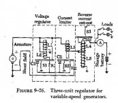
The Three Unit Regulator for Variable Speed Generators contains:
1. Voltage Regulator
2. Reverse Current Relay (cut-out)
3. Current Limiter
1. Voltage Regulator
Construction
Refer to Figure 9-26
The voltage regulator consists of an electromagnet with two windings (L1, L2) and a set of points C1 held closed by a spring S1. L1 is in parallel with the output of the generator, so it has generator output voltage dropped across it. Points C1 are in series with the field windings. R1 is in parallel with C1. L2 is in series with R1.
Operation
When the generator starts rotating, the armature cuts through field lines of the residual magnetic field in the field winding cores and case. This induces a small voltage (2V±)in the armature. Current flows through the output wire to L1 to ground, also through C1, C2, and the field windings to ground. When current flows through the field windings, it creates a stronger magnetic field. When the armature rotates in the stronger field, more voltage is induced in it. The voltage will rise until it is the rated voltage. Then the magnetic field in L1 is strong enough to open C1, forcing the field current through R1 and reducing it. Less field current means less magnetic field strength in the field windings, reducing output voltage. L1 can’t hold C1 open and S1 closes C1. The points will vibrate open and closed.
RPM increase
If the RPM increases, the armature cuts field lines faster and more output voltage is induced in it. Current flow through L1 increases. When the current thru L1 increases, the stronger magnetic field will hold C1 open longer, decreasing field current. When field current decreases, the magnetic field strength decreases, decreasing the output voltage back to the rated voltage.
RPM decrease
If the RPM decreases, the armature cuts field lines slower and less voltage is induced in it. Current flow through L1 decreases. When the current thru L1 decreases, the weaker magnetic field will let S1 hold C1 closed longer, increasing field current. When field current increases, the magnetic field strength increases, increasing the output voltage back to the rated voltage.
Purpose of L2
Current flows through L2 when C1 is open. L2 is wrapped the opposite direction of L1. This creates a magnetic field that partially cancels the field of L1 and lets S1 pull C1 closed.
Load Increases
As the pilot turns more loads on, more current is demanded to run those loads. The generator is producing a certain amount of power, so the increased current will cause the output voltage to drop. The lower output voltage will cause the current through L1 to decrease, so C1 will stay closed longer, increasing the field current. The increased field current will increase the magnetic field strength of the field windings, inducing more output voltage, so the generator will maintain the rated voltage as the load is increased.
Load Decreases
If the pilot turns loads off, less current is needed to run those loads. This will cause the output voltage to try to rise. Current through L1 increases, causing a stronger magnetic field. C1 will open longer, decreasing field current. The magnetic field decreases causing the induced output voltage to decrease back to the rated voltage.
2. Reverse Current Cut-out
Purpose
The reverse current relay or cut-out connects the generator to the bus to power the loads when the output voltage reaches a set point. It also removes the generator from the bus by opening if the battery voltage is higher that generator voltage.
Operation
Generator Powering the Bus
Spring S3 holds Points C3 open. Generator output current flows through L5 to ground. When the generator output voltage reaches its rated value, the current through L5 creates magnetic field strong enough to close C3 against S3. Now the generator is powering the bus. Generator output current now also flows through L4. L4 is wrapped in the same direction as L5, therefore, its magnetic field aids that of L5.
Generator Removal from Bus
If the generator output voltage falls below battery voltage, battery current will flow backwards through L4. The magnetic field created by this flow will cancel the field from L5 and S3 will open C3. This isolates the generator from the bus and the battery is powering the loads.
3. Current Limiter
Purpose
The purpose of the current limiter is to protect the generator from putting out too much current. It does this by reducing the field current to reduce the output voltage and
therefore, by Ohm’s Law, the output current.
Construction
The current limiter consists of an electromagnet L3 in series with the bus that opens the points C2 against the spring S2.
Operation
If the pilot turns on too many loads, the generator output current flowing through L3 will create a magnetic field strong enough to open C2. This forces the field current to go through R2, reducing it. This decreases the output voltage and therefore, the output current.
I have attached the schematic and the notes. I couldn't attach the notes, so they are in the body. Sorry!
So imagine, if you will, it's 8:00 am. You are in a classroom full of snot-nosed youngsters right out of high school, smart-aleck ex-military aircraft mechanics, mid-life career-changers anxious to get a job as an aircraft mechanic, and retired aerospace engineers eager to learn. Some are talking, some drinking coffee and trying to wake up, and all are looking at the chalkboard, upon which is drawn a schematic. The overhead projector is showing the same schematic on a screen to the side. Each student has a copy of the schematic plus lecture notes on his desk, too. Aircraft generators and voltage regulators of various types and in various stages of dis assembly are on a SteelAge desk in front of the class.
Then in walks an Old Hippie carrying a notebook, cup of water, and a pointer. He begins to speak...
Sources of Aircraft Electrical Power
Theory of Generation of Electricity
1. When a conductor is moved through a magnetic field, a voltage is induced in it.
2. If a complete circuit exists, the voltage will cause a current to flow.
3. The amount of voltage induced depends on the rate at which the lines of flux are "cut" by the conductor. The greater the rate, the more voltage is induced.
Two things can change the rate at which the flux lines are cut:
1. The strength of the magnetic field (flux density)
2. The speed of the conductor movement.
4. The direction of flow of the induced current can be found by using the left-hand rule for generators.
Thumb: Direction of conductor movement
Index finger: Direction of lines of flux (Said to run from North to South)
Middle: Direction of induced electron flow
5. The magnetic field may be provided by a permanent magnet or by an electromagnet.
Electromagnet:
When current flows through a conductor, a magnetic field forms around the conductor.
If the conductor is formed into a coil the lines of flux are concentrated making a stronger magnetic field. If the coil is formed by wrapping a conductor around a soft iron core, the lines of flux are concentrated even more, increasing the strength of the magnetic field that much more.
In any electromagnet, the strength of the magnetic field is directly proportional to the amount of current flowing through it:
More current makes a stronger field.
Less current makes a weaker field.
A. DC Generators
Purpose
The generator powers the electrical loads and charges the battery.
1. Parts of the Generator
a. Field Windings
Copper wire wrapped around pole shoes (soft iron core)
Create a magnetic field when current flows through them.
b. Armature
Copper wire wound around a soft iron core that is attached to a shaft. The aircraft engine (or possibly the airstream) rotates the armature.
An AC voltage is induced in the armature windings when it rotates in the magnetic field of the field windings.
c. Commutator
Copper segments on the end of the armature shaft insulated from each other by mica. Opposite segments are connected to a common winding in the armature.
The segments carry the output current from the armature to the brushes.
In conjunction with the brushes, turns the AC induced in the armature into DC for the output current.
d. Brushes
Blocks of carbon that are held against the commutator (one segment at a time) by springs attached to the case.
Carry the output current from the commutator to the output terminal of the generator.
2. Operation
As the armature rotates in the electromagnetic field created by the field windings, an AC voltage is induced in it. A current will flow only through the segments of the commutator that touch the brushes. These segments are connected to the windings in the armature in such a way that direct current flows through the brushes and out the output terminal.
Until the current flows through the field windings from the output of the generator, the magnetic field is due to the residual magnetism left in the pole shoes in the field windings left from the last time the engine ran. This allows the whole process to start.
If the residual magnetism is lost, the generator will not put out current. Residual magnetism can be restored by "flashing the field": connecting a jumper from the battery to the field windings to run current through them and magnetize the pole shoes.
B. DC Voltage Regulation
1. Need for Voltage Regulation
1. If the RPM of the engine driving the generator changes, the speed with which the flux lines are cut will change, causing the induced voltage to change.
2. If the electrical load on the generator changes, the output voltage will change.
3. The loads powered by the generator or alternator want the voltage to remain constant so #1 and #2 are unacceptable.
2. Theory of Voltage Regulation
Since the strength of the magnetic field changes the amount of voltage induced, the voltage can be kept constant by changing the current through the magnetic field. This will change the strength of the field and, therefore, the output voltage.
Examples:
1. If the RPM increases, the voltage will try to increase.
The voltage regulator will sense this increase and decrease current to the field.
The decreased current to the field will cause the strength of the field to decrease.
The decreased field strength will induce less voltage.
The voltage is back to normal.
2. If the pilot turns on more loads, the voltage will try to decrease.
The voltage regulator will sense this decrease and increase current to the field.
The increased current to the field will cause the strength of the field to increase.
The increased field strength will induce more voltage.
The voltage is back to normal.
Vibrating Point Three-Unit Regulator
The Three Unit Regulator for Variable Speed Generators contains:
1. Voltage Regulator
2. Reverse Current Relay (cut-out)
3. Current Limiter
1. Voltage Regulator
Construction
Refer to Figure 9-26
The voltage regulator consists of an electromagnet with two windings (L1, L2) and a set of points C1 held closed by a spring S1. L1 is in parallel with the output of the generator, so it has generator output voltage dropped across it. Points C1 are in series with the field windings. R1 is in parallel with C1. L2 is in series with R1.
Operation
When the generator starts rotating, the armature cuts through field lines of the residual magnetic field in the field winding cores and case. This induces a small voltage (2V±)in the armature. Current flows through the output wire to L1 to ground, also through C1, C2, and the field windings to ground. When current flows through the field windings, it creates a stronger magnetic field. When the armature rotates in the stronger field, more voltage is induced in it. The voltage will rise until it is the rated voltage. Then the magnetic field in L1 is strong enough to open C1, forcing the field current through R1 and reducing it. Less field current means less magnetic field strength in the field windings, reducing output voltage. L1 can’t hold C1 open and S1 closes C1. The points will vibrate open and closed.
RPM increase
If the RPM increases, the armature cuts field lines faster and more output voltage is induced in it. Current flow through L1 increases. When the current thru L1 increases, the stronger magnetic field will hold C1 open longer, decreasing field current. When field current decreases, the magnetic field strength decreases, decreasing the output voltage back to the rated voltage.
RPM decrease
If the RPM decreases, the armature cuts field lines slower and less voltage is induced in it. Current flow through L1 decreases. When the current thru L1 decreases, the weaker magnetic field will let S1 hold C1 closed longer, increasing field current. When field current increases, the magnetic field strength increases, increasing the output voltage back to the rated voltage.
Purpose of L2
Current flows through L2 when C1 is open. L2 is wrapped the opposite direction of L1. This creates a magnetic field that partially cancels the field of L1 and lets S1 pull C1 closed.
Load Increases
As the pilot turns more loads on, more current is demanded to run those loads. The generator is producing a certain amount of power, so the increased current will cause the output voltage to drop. The lower output voltage will cause the current through L1 to decrease, so C1 will stay closed longer, increasing the field current. The increased field current will increase the magnetic field strength of the field windings, inducing more output voltage, so the generator will maintain the rated voltage as the load is increased.
Load Decreases
If the pilot turns loads off, less current is needed to run those loads. This will cause the output voltage to try to rise. Current through L1 increases, causing a stronger magnetic field. C1 will open longer, decreasing field current. The magnetic field decreases causing the induced output voltage to decrease back to the rated voltage.
2. Reverse Current Cut-out
Purpose
The reverse current relay or cut-out connects the generator to the bus to power the loads when the output voltage reaches a set point. It also removes the generator from the bus by opening if the battery voltage is higher that generator voltage.
Operation
Generator Powering the Bus
Spring S3 holds Points C3 open. Generator output current flows through L5 to ground. When the generator output voltage reaches its rated value, the current through L5 creates magnetic field strong enough to close C3 against S3. Now the generator is powering the bus. Generator output current now also flows through L4. L4 is wrapped in the same direction as L5, therefore, its magnetic field aids that of L5.
Generator Removal from Bus
If the generator output voltage falls below battery voltage, battery current will flow backwards through L4. The magnetic field created by this flow will cancel the field from L5 and S3 will open C3. This isolates the generator from the bus and the battery is powering the loads.
3. Current Limiter
Purpose
The purpose of the current limiter is to protect the generator from putting out too much current. It does this by reducing the field current to reduce the output voltage and
therefore, by Ohm’s Law, the output current.
Construction
The current limiter consists of an electromagnet L3 in series with the bus that opens the points C2 against the spring S2.
Operation
If the pilot turns on too many loads, the generator output current flowing through L3 will create a magnetic field strong enough to open C2. This forces the field current to go through R2, reducing it. This decreases the output voltage and therefore, the output current.

 :wink:
 A friendly reminder - be careful what links you click on here. If a link is posted by someone you don't know, or the URL looks fishy, DON'T CLICK. Spammers sometimes post links that lead to sites that can infect your computer, so be mindful what you click.