• Hey there Guest!
    If you enjoy BCF and find our forum a useful resource, if you appreciate not having ads pop up all over the place and you want to ensure we can stay online - Please consider supporting with an "optional" low-cost annual subscription.
    **Upgrade Now**
    (PS: Subscribers don't see this UGLY banner)
Tips
Tips

Proper use of British Crimping tool

M

Member 10617

Guest
Guest
Offline
Can someone explain to me exactly how to use the British Crimping tool properly? The tool seems straightforward enough, but there are two faces to the tool, and it is not clear which one should face to bullet (the large hole or small hole) and which should face the insulated wire. In addition, I'm not sure what to make of the little "tail" that is produced when compressing a bullet. It seems that the "tail" would prevent the bullet from going completely into the Lucar connector.
 

DNK

Great Pumpkin
Country flag
Offline
Ed, Show us a couple of pics of your tool, :blush: er,Crimping tool
 

BobbyD

Jedi Knight
Offline
If you're talking about the tool below the tip of the bullet sits in the recessed section with the tail and wire out the back of the tool. You need special crimping bullets for this tool and the wire size and bullet size have to "match"

BWTools.jpg


Here's what a crimped bullet looks like. The crimp shape is multi-sided

BulletCrimp.jpg
 

PeterK

Yoda
Offline
I usually finish the tail with a spot of solder, then file the end smooth.
 

DNK

Great Pumpkin
Country flag
Offline
Bobby has what I have and is a recommended Dan Master's tool
 

KVH

Darth Vader
Country flag
Offline
I soldered bullets today while fixing my turn signals. I had to replace two corroded wires.

I truly do not understand the theory.

When I solder the wire to the bullet, the plastic jacket just melts away, so how is one supposed to crimp anything for greater strength after first soldering the tip?

As for some styles of crimp bullets, it appears the crimp is in the grove near the tip, correct?

Now, about the capillary action. Which direction is the capillary action? Tip backward, or from the rear of the bullet forward? Or is it toward the heat source?
 
OP
M

Member 10617

Guest
Guest
Offline
Don and Bob,

Many thanks. I have the TT85 crimping tool and mistakingly thought that the crimp was to be applied at the bottom (open end) of the crimping bullet. I see now that the crimp is supposed to be at what I'll call the neck or the groove near the tip of the bullet. However, that doesn't seem leave much room in the bullet for the solder (only in the head of the bullet).

Bob's photo of what the crimped bullet should look like shows the crimp around the neck of the bullet, near the tip.

Just to make sure I have understood what to do, here is a diagram. It shows the crimp at the neck, and the crimping bullet in the crimping tool. Is any of this wrong?
 

Attachments

  • 24122.jpg
    24122.jpg
    23.1 KB · Views: 424
OP
M

Member 10617

Guest
Guest
Offline
UPDATE: I have just received an email from British Wiring with instructions on how to use the British Crimping tool I purchased from them, and I will share the information with you.

"The first thing you need to make sure is that the bullets you are using are crimp-able. There are some bullet connectors that are not designed to be crimped, and must be soldered.

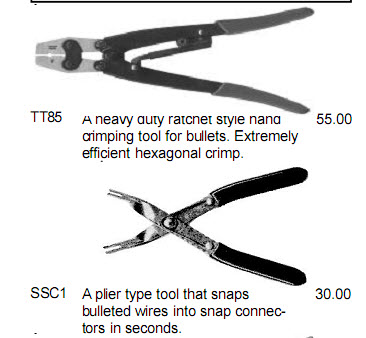
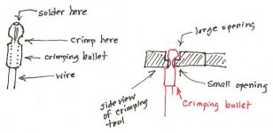
The hexagonal cut-out on the tool that is marked "crimp here" is where you place the collar of the bullet to crimp. It does not matter which direction the bullet is placed. The only reason one side has a larger hole than the other is that the one side needed to be machined out to get the proper width crimp.

You will need to strip 1/4" of insulation off the wire. Slide the wire into the bullet. Place the bullet into the crimper, and close the tool. When you crimp, you squeeze the crimper together until it unlocks (it will click multiple times) and releases the bullet.

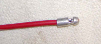
The shape of the bullet will not be affected when you crimp the bullet properly."

.... And so, this seems to be all that we need to know, except how to tell a crimp-able from a non-crimp-able bullet...


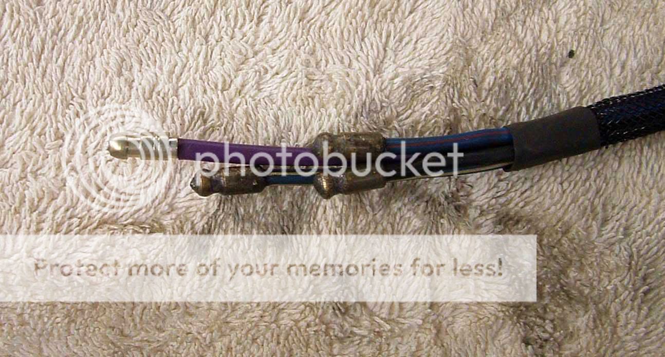
UPDATE to the UPDATE. I have followed the British Wiring instructions and the crimping tool cuts the top of the bullet completely off each time??? Any thoughts on this? Are Moss bullets non-crimpable?
I am using Moss 162-200 Wire Tip, solder type bullets. It appears that these, which are the only ones Moss supplies, are non-crimpable.


UPDATE to the UPDATE to the UPPDATE (!). I just called Moss and the technician there says that Moss wire tip, solder type bullets (162-200) cannot be crimped. They sell a solderlsess one that can be crimped but it cannot be soldered. So, I wonder what bullet those of you are using that can be both soldered and crimped? Moss technician says that soldering is sufficient for the 162-200 bullet.
 

Darrell_Walker

Jedi Knight
Silver
Country flag
Offline
LexTR3 said:
They sell a solderlsess one that can be crimped but it cannot be soldered. So, I wonder what bullet those of you are using that can be both soldered and crimped? Moss technician says that soldering is sufficient for the 162-200 bullet.

My guess is that they meant that the crimp type bullets can not be ONLY soldered.
 
OP
M

Member 10617

Guest
Guest
Offline
Darrell,

Don't know, but Moss technician said that the crimp type bullets cannot be soldered. I am curious as to what kind or brand of bullets people are using who both crimp and solder them. Evidently it is not the Moss #162-200. And if not, I wonder why people are not using the #162-200. Have people found problem with them?
 

KVH

Darth Vader
Country flag
Offline
Mine are from a local electronics shop. They have a crimpable rear, and a hole on the front. I solder the wires in, then heat shrink a good sleeve up to the bullet. I do that because the jacket melts every time I solder the bullet head onto the wire. But I'm still an amateur.
 

BobbyD

Jedi Knight
Offline
I bought this tool when I did the AAW harness which came with bullets that can be crimped and soldered. I actually crimped and soldered each bullet. I applied heat to the side of the bullet and let it draw the solder in from the tip of the bullet. Some people swear by crimping only, others solder only, others do both and some say you should only do one or the other...... take your pick

British Wire sells the bullets that can be crimped and soldered. They are sized based on the wire size you'll be using.

The wire that comes with the AAW harness has a very unique covering that melts at a very high temperature. I did all of my soldering with a mini butane torch and never melted any of the wire coating.

BTW....... I really wish I had also bought that British Wiring tool that snaps bullets into the connectors. Guys who have bought it, love it for its ease of use.
 

TR3driver

Great Pumpkin - R.I.P
Offline
I don't know what Moss sells as 162-200, but as I mentioned before it is important IMO that the bore fit the wire snugly for a good solder joint without crimping. (It also has to fit snugly for a good crimp joint.) Since the "solder type" bullets are "one size fits all", they cannot fit the various sizes of wire snugly. They also only attach to the wire for a very short distance at the tip, while the crimp-type bullets will attach all through the crimp area for a stronger connection.

So I buy the crimp bullets from TRF, and attach them with solder only. Maybe I "can't do that", but it seems to work very well for me. I have never had one fail in more decades than I care to count. TRF has 4 different sizes, LUCWB321 (smallest) through LUCWB324 (largest); which I believe correspond to 9, 14, 28 and 44 strand wire (as per the British Wiring catalog). But I just bought an assortment of them, and each time I pick the smallest one that will fit the wire at hand. On occasion, I have even drilled out a small bullet to suit.

Here's a shot of one installed on 14 AWG wire:

Oneextrawire.jpg
 
OP
M

Member 10617

Guest
Guest
Offline
Randall and others. Many thanks. The Moss bullets are intended as one size fits all, so it is logical that they will not fit all wire sizes. But they do fit the Lucar connectors that are referenced on the same page of the catalog.

I think I will order an assortment from TRF and -- I suppose -- an assortment of Lucar connectors.

I would like to soldr and crimp the bullets.
 

bigjones

Jedi Warrior
Bronze
Country flag
Offline
Ed,

I'm sorry you are having such a miserable time with the crimping tool.

I can confirm that the Moss bullets cannot be crimped. I got the crimpable kind from British Wiring, along with the tool, and they work just fine - why not just order a bunch from BW, instead of TRF? That way you know what you are getting, ie, crimpable bullets.

Good luck!
 
OP
M

Member 10617

Guest
Guest
Offline
Thanks, all.

I think I'll order one of those tools to snap on the connectors and an assortment of bullet connectors at the same time from British Wiring. But before I do, can the British Wiring crimpable kind also be soldered?

BTW, the person I spoke with at TRF this afternoon said that all sizes of bullets fit in the same size Lucar connector. I'm not sure how this is possible unless the bullets are all the same size but the holes for the wire are different (?)
 

TR3driver

Great Pumpkin - R.I.P
Offline
LexTR3 said:
I'm not sure how this is possible unless the bullets are all the same size but the holes for the wire are different (?)
Someone give that man a See-gar !
:iagree:

BTW, TRF also sells the "solder only" bullets, as well as the "fold over the wire" bullets. The latter are Prince of Darkness incarnate, IMO, not for ordinary mortals to mess with.
 

TR3driver

Great Pumpkin - R.I.P
Offline
LexTR3 said:
But they do fit the Lucar connectors that are referenced on the same page of the catalog.
I don't believe that is correct. "Lucar" normally refers to flat blade connectors that were used on later cars to connect to switches and such.

In this blowup from the Moss catalog, only item 66 is a "Lucar" connector (67 is a vinyl insulator for 66). Items 61-63 are the three types of bullet sleeve.
 

Attachments

  • 24127.jpg
    24127.jpg
    20 KB · Views: 334
Similar threads
Thread starter Title Forum Replies Date
R TR6 Proper alignment of gearbox front cover plate Triumph 3
sundown TR6 Proper ring gaps Triumph 6
R Proper Aluminum Sump Installation Austin Healey 13
TulsaFred Proper attachment of Demister tubes and vents Spridgets 3
M Proper running temp for 1275 Spridgets 28
Bob_Spidell Proper Engagement of Overdrive Austin Healey 8
M Hauling a Spridget - Proper tie down technique? Spridgets 15
M Proper oil? Spridgets 6
Got_All_4 TR2/3/3A Which oil cap decal is proper to use with this cap Triumph 7
M What is the proper oil for Bugeye engne and transmission Spridgets 6
M Choosing the proper inner tube Spridgets 6
T Proper location for rocker shaft 'Screw-Locating' Spridgets 3
KVH TR4/4A Proper Ring Gap Triumph 4
bugedd Fuel Leak and Proper Routing Spridgets 9
M '69 Sprite Proper Seats Spridgets 3
R Proper Timing Technique '60 BN7 Austin Healey 0
bighealeysource Proper way to "seat" ball bearings in OD operating valve Austin Healey 3
britlover proper tire size to replace 5.90-15? Austin Healey 16
Got_All_4 TR2/3/3A Is this the proper Boot lid seal? Triumph 9
K TR2/3/3A Proper size of "set screw/bolt?" for top of trans..... Triumph 1
J TR2/3/3A Proper distributor for 1960 TR 3A Triumph 5
K Proper SU Adustment Austin Healey 16
T proper jump starting technique Austin Healey 2
F Proper location of chrome loop for spare tire strap? Austin Healey 2
M Proper torque for cylinder head nuts Triumph 20
R proper antifreeze? Spridgets 2
B MGB Proper MGB Overdrive speedometer MG 3
A Proper Gear oil? Triumph 9
brgrmyster Proper finish on luggage floor angle assembly? Triumph 0
M Restoring proper order to spark plug wires Triumph 36
M Proper use of the Gunson Colortune Triumph 41
brgrmyster GT6 Proper stock color oil filter canister 68 GT6? Triumph 7
G Proper Torque for Water Pump Install MG 4
tri_carb_healey brake drum work, proper jack points Austin Healey 12
tri_carb_healey proper type of gasoline Austin Healey 6
bighealeysource Pics needed on proper way to fold up top on BN2 Austin Healey 1
M Proper Brake Fluid For 1960 Morris Minor Pick Up Spridgets 8
J Proper brake fluid Austin Healey 19
af3683 TR2/3/3A Proper Use of Jack Stands on Rear of TR3B Triumph 9
M Proper servicing of overdrive Triumph 15
af3683 TR2/3/3A Proper Oil for TR-3 Steering Box Triumph 22
M TR2/3/3A Proper servicing of TR3 air filters Triumph 20
T proper use of exhaust clamps Austin Healey 11
rggav Proper way to remove and reinstall wire wheels? MG 6
pjsmetana Spitfire Proper Jack Points? Spitfire Triumph 8
H Proper Installation of shock mounting plate Austin Healey 3
P TR2/3/3A Proper screws for a TR3A interior Triumph 4
A Proper Oil Filter MG 22
6 Whats the Proper Way to Remove Tie rods on AH BJ8? Austin Healey 17
RJS Oil Pressure Relief Valve - Proper Function Triumph 2

Similar threads

Top