• Hi Guest!
    You can help ensure that British Car Forum (BCF) continues to provide a great place to engage in the British car hobby! If you find BCF a beneficial community, please consider supporting our efforts with a subscription.

    There are some perks with a member upgrade!
    **Upgrade Now**
    (PS: Subscribers don't see this gawd-aweful banner
Tips
Tips

TR4/4A TR4A Assembly by a rookie (me!)

For my excuse for lack of progress, my daughters and I spent some time at the Pittsburgh Vintage Grand Prix! A long drive, but well worth it!

Quite jealous, Mike! Very likely some of my old pals were in attendance.

Did you get out to the events at PittRace in Wampum?
 
Hi KVH, Great questions! I’ll answer shortly; likely tomorrow. I’m on the road today.
 
Quite jealous, Mike! Very likely some of my old pals were in attendance.

Did you get out to the events at PittRace in Wampum?
We did not - arrived Friday night and back Saturday afternoon. The “avenue of speed” on Friday night with all the cars roaring in procession along the “main street” (Forbes) is always fun. The races in Wampum are special - faster and spectators have a bigger view of the track. In Schenley you only see one, maybe two corners. We also missed the Monday night Walnut Street show - always good for one or two rare (i.e. old) Ferraris (complete with guards) plus an array of just interesting cars from all ages.

What I like the most is the open and inviting nature of the folks showing / racing their cars. My daughters have sat in all kinds of great machinery, from Rolls Royce to VW and everything inbetween - invited by the proud and watchful owners. I suspect the events at Put-in-Bay and Watkins Glen have a similar nature about them.
 
WOW, you sure did a great job. I'm about ready to start my full engine rebuild, and have some questions, a lot. I hope you don’t mind, but I’m a bit nervous after letting my block sit for 2 years:

Understand the nerves. My block sat for about five years, during which the shop flooded (underwater) and the block went back to the engine rebuilders for a second rebuild! (Kudos to my mechanic for being upfront with me.)

a) Your crank pulley and timing gears were not marked, right? Looking at your set up, can you explain just a bit further? For instance, when you measured 110 after TDC for the one valve fully open, what did you do with that information? What adjustment did that lead you to? In other words what readings do you take from the wheel and how do those translate to another adjustment you make? I actually didn't find the Macy's article that helpful (to me).
Correct. I marked the new crank pulley for TDC - drilled a hole in it so that the “pointer” on the timing cover points to the hole at TDC. I did not mark my timing gears. However, to set engine timing, I did not use any marks - I attached a timing wheel to the crankshaft and a bolted a piece of stiff wire to one of the threaded holes on the front of the engine as my pointer. (Does not matter where the wire points, but it can’t move during timing.) First step is to find TDC; I used the Macy’s article for that: Fix a bolt pointing into the piston, and bump it going up one way, bump again going up the other way. TDC is exactly halfway between those bumps. (Like you, I did not find the Macy’s article of further value.) I forget the exact timing, but basically you want the intake valve to be peak open at XX degrees after top dead center. However, to find peak opening is difficult, because it is fully open for a few degrees. So I found the maximum opening with a dial indicator, then found the angle when the valve is 0.1 (or any other fixed value) before fully open, and the same after fully open.

I found this video helpful: https://www.google.com/url?sa=t&rct...=W0zvpImhvHc&usg=AOvVaw2JT1SxdF7ESlYxoMIfbuN1

b) those new pushrod tubes--did you use that flaring tool for the fit? And only because the old tubes were ruined somehow, or missing?
Correct. I oversize machined the holes in the head (actually my machinist did), inserted the tubes with blue loctite, and flared. I am not sure why the tubes were missing - assume the head was “hot tanked” and they dissolved.

c) what issues did you have with the thrust washers and bearing clearances, or was that part done at the shop?
That part was done by the shop, but I checked, and found all to be within spec.

d) just being an old grandma, did you remember the washer that goes ahead of the cotter pin on the timing chain tensioner?
Yep! (And I appreciate you being an “old grandma”… grandmothers are great; missing washers not so!)

e) what kind of gasket sealer did you use on that front engine cover? A friend swears by some “Motorcraft” gray product. I don’t recall if you’re supposed to put sealer on both sides of that gasket—how did you handle it? I'm wondering what your criteria was for choosing red vs. blue RTV, or is that blue Hylomar I see there? Related to this, did you make much use of Permatex Aviation or Permatex High Tack?
I used Indian Head Shellac, mainly because I spent money on it, it smells nice, and it is what was used at the time. I think Hylomar Blue, or Permatex Aviation is a better material, and used that on parts with a higher chance of needing service in the future, e.g. oil pan.

f) you did not use a solid copper gasket, correct? You used a composite one, copper or some alloy sandwich gasket?
I used solid copper (Payen brand) plus copper spray.

g) with the new sleeves and figure 8 gaskets, either the clearance is .003 to .005, or close, or its not. What can you really do about it? I’ve always been within clearance, but wonder the workaround is if not. You sealed the sleeves with WellSeal?
You can adjust the clearance with gaskets made of different material thicknesses - but you likely have to cut your own. I did not seal the sleeves, but hope the engine shop sealed the Fo8 gaskets.

h) about that wood cradle for the engine—to lower the engine and attach the transmission. Can I see a pic?

(I can’t recall how I handled that last time, but I’m fairly certain I rested to engine on blankets to avoid pressure on the oil pan. Or I may have left the hoist partly under tension. I do recall feeling that everything would have been much easier, including sliding the engine/transmission back into the car if I’d just left the oil pan off and installed it later from underneath. Any thoughts on that? Too convoluted for the payoff?)

The oil pan clearance to that front frame member is very tight on reinstallation of the engine/transmission, and I did scrape a bit.
Will attach below - took a few iterations to get right :smile:. I am nervous about getting dirt/debris inside the engine, and prefer to keep the oil pan in place. I suppose you could make up a plate (only needs a few holes) to cover the bottom of the engine. But the gearcase drops below the oil pan flange, so you’d have to raise the engine before mating the two.

i) did you end up using the Viton rear main seal? Any issue there?
I used the stock seal.

j) your fan damper looks custom? Am I wrong? (though you kept the stock fan)
It is stock… at least I hope so! Is there anything that looks funny or off that I should be aware of? My intent is to build it as stock as practical.

Well, I’ll be lucky if you have the patience to review, but any thoughts or experiences would be appreciated. Love seeing these cars restored. They deserve it, and the engineers who put that Triumph manual in print ought to be celebrated eternally.
Yes!!
 
First iteration:
398261A1-84EC-417B-B3BB-EEE0BE267C2E.jpeg


Problem:
CB7E2B52-7310-466D-AAB7-CCB1AA1610C4.jpeg


Second iteration:
9A176114-4922-4697-8D32-425511F3AAC6.jpeg

C1ED65D8-0953-40D6-A219-7FC526C41A41.jpeg
 
I made the exact same mistake.

B4D9259B-13AC-47E6-B871-EC5293AF5E65.jpeg


this is a furniture dolly with a homemade cradle which actually started to deform under the engines weight. I beefed it up a bit by sliding another piece of wood under the cradle on both ends. It’s been like that for about 2 weeks now and all seems good.
 
That was very helpful. Thanks for all of the answers. I have just a few things: first, I’m wondering how you were able to torque the fan extension bolt (dog bolt) to the crankshaft at over 100 ft pounds. Would I be correct to assume that you uses a block of wood to stop the crankshaft from turning? Second, certainly no big deal, but your fan extension does not look stock; but only because it appears it has been machined to help avoid interference with the steering tube. I’m still studying that timing indexing/process and the engine cradle. Looks cool.
 
first, I’m wondering how you were able to torque the fan extension bolt (dog bolt) to the crankshaft at over 100 ft pounds. Would I be correct to assume that you uses a block of wood to stop the crankshaft from turning? Second, certainly no big deal, but your fan extension does not look stock; but only because it appears it has been machined to help avoid interference with the steering tube.
Yes, block of wood. Worked a charm. The only concern I had was the bolt head is (by design) slightly rounded. But the socket did not slip at the high torque.

I am not sure about the fan belt extension… it was what came with the car. I found this image in another forum, but it is the only one I found that shows the groove: > TR3 fan hub extention : TR2 & TR3 Forum : Triumph Experience Car Forums : The Triumph Experience <
 
WOW I’d never seen reference to a third extension, but I’ve also never seen a post in error from Randall or Geo.

We unfortunately lost Randall a while back, never to be forgotten. Knew everything about TRs and more. Former GPS software engineer.
 
Now I’m wondering about the wheels on those fabricated engine dollies. Is the idea that you put the transmission on wheels also and just slide them together, avoiding all the muscling and horsing? Or are you putting the engine on wheels with the idea that you will block the wheels when you slide the transmission on?
 
The latter; I pushed the engine wagainst the wall - using a thick/soft piece of foam and muscles the transmission home. Making a transmission dolly of the same height sure would have made it easier - but would have taken a lot of time. I blocked the rear of the transmission with a stack of 2x4s so I only had to “wrestle” the front half.
(I am behind on posting updates…)
 
Hi all,

Apologies for the long delay since posting. I’ve got a new job (a wonderful change), and have lost my Internet access and lunchtime forum forum perusing! I’m posting this using my iPhone… Apologies for some of the pictures being upside down!

Updates:
1. Installed the shift fork and throwout bearing in the transmission. I added a grade 8 bolt in the center of the fork, within a nylock on the backside.
2. Installed the flywheel, using ARP fasteners.
3. Installed the clutch. (I had the fly wheel and clutch assembly balanced by local machine shop prior to install.)
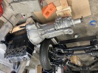
4. Here comes the bride… Marriage of the engine to transmission. The OD is the heavy side of the transmission! I raised the the aft end of the transmission up on a stack of two by fours. The engine, on a rolling dolly, was pushed against the wall with a piece of foam between engine and wall. Transmission was in fourth gear, allowing the input side to quickly align on spinning the output side. It took a bit of grunting and questioning, and then suddenly the two parts click together beautifully. (Again, similarities to marriage… at least my own. :smile: )
5. Then I hoisted the assembled engine onto the chassis. This took a bit of fiddling to get the engine level during the lift. (It is much easier to line up the engine mounts with a horizontal engine.) Once I got the lifting arrangement correct, it was quite easy.
6. Admired my work with a celebratory drink, feeling like a big kid!
7. My rockers arrived from rocker arms unlimited, I installed the push rods (with a healthy coating of assembly lube), the rocker arms, and set the clearances using feeler gauges.
8. Installed the starter and dynamo. (I’m going old school!) Sports and Classics in Connecticut was able to provide me the correct shim for the starter; TRF the bits for the generator.
9. Installed the intake and exhaust manifold. I painted the intake with rustoleum (aluminum primer plus silver topcoat). I would like to get the exhaust manifold ceramic coated, but this will not happen until after the engine has been initially tuned. Plenty of anti-seize used!
10. Installed a falcon stainless steel exhaust. This took a little bit of fiddling, but ultimately went together extremely well. The hardest part was inserting pipes to the correct depth, such that the exhaust at the end of the car lined up with its proper location. Again, lots of anti seize!
11. And finally, last night I installed the driveshaft.

A few comments:

Kudos to TRF for providing complete kits of high-quality. They provide the proper manifold and exhaust nuts (brass). They also provide Clevelok (spelling?) nuts for the propshaft, as recommended by Randall. Also, their webpage is very clear with how many bits you need. They don’t sell ARP fasteners, and when I bought them from a different supplier I didn’t get the right quantity. I know TRF is not perfect, but it sure seems like they try.

How does one torque the prop shaft? If I’m reading the manual correctly, it requires a torque of 80 to 100 ft-lbs. I can’t get a socket on the bolt heads. How do you do it?

Finally, anything I should do or check prior to putting the body back on the chassis?


BA218D23-D605-4C81-8674-BFB03EF9F681.jpeg

DAFC4D30-A43D-4BB2-B074-F7DB0CA18DBF.jpeg

32368C77-32A5-422D-922B-5CE77C9111D1.jpeg

5A6DF331-FFC8-448F-BC1F-1F366673F070.jpeg

D13F4EC5-9544-42BF-AB3F-C503464F5115.jpeg

8FF841F5-6DAE-47AA-BC3F-DDF4951A1AB8.jpeg

A4282FDC-03B8-4886-9A87-46F9FBB4162D.jpeg

01467280-891F-444B-8934-5A5BDDD9E5DC.jpeg
 

Attachments

  • 6887EAC3-6F42-4FB5-B802-5D364D27E37C.jpeg
    6887EAC3-6F42-4FB5-B802-5D364D27E37C.jpeg
    402.2 KB · Views: 71
Last edited:
How does one torque the prop shaft? If I’m reading the manual correctly, it requires a torque of 80 to 100 ft-lbs. I can’t get a socket on the bolt heads. How do you do it?

Update; basis a little internet sleuthing, it seems I am (completely) misreading the manual… 80-100 is incorrect.

Seems the right answer is 25-30 ft-lb. Very doable with two hand wrenches.
 
Beautiful work. Amazingly patient and detailed effort. Incredible you have the body off the chassis and were able to do that. If I were at your stage, having done everything you've done, I know what I'd be thinking: "I'll have the first totally restored TR4A that doesn't ever leak even a single drop of oil." And then I'd check every day . . . .
 
Thanks for the compliments! This is my first time for much of this work, and I am enjoying every minute of it. (Excepting occasional outbursts when I smack my finger or similar! A memorable quote from Steinbeck’s Grapes of Wrath: “"H_ll, no! I never fixed no car in my life 'thout cuttin' myself. Now it's done I don't have to worry no more.")

However I don’t think it will be leak-free. It is British, after all. More importantly, I decided to leave the work already done alone and not use the updated rear seal.
 
Last edited:
Great work, Mike! When do we hear th' "VROOM!" post? :D :bananawave:
 
The carbs will be a "bolt 'em on, hit th' key" job. Water pump a bit more involved. But it's all exciting for sure.
 
I have yet to see one not leak somewhere and it always looks like rear main, but it is usually the breather pipe or pan. The crank shafts have the scrolled deal on the end to through the oil back into the engine. Yes I love the pain of the first startups keep us posted

steve
 
Back
Top