-
 Hi Guest!
If you appreciate British Car Forum and our 25 years of supporting British car enthusiasts with technical and anicdotal information, collected from our thousands of great members, please support us with a low-cost subscription. You can become a supporting member for less than the dues of most car clubs.
There are some perks with a member upgrade!**Upgrade Now**
(PS: Subscribers don't see this gawd-aweful banner

Tips
- We have a special forum called "Member Articles" where you can submit actual articles for consideration for publication. Learn More
- Don't have an Avatar? If not, your avatar will default to the 1st character in your username. Go into "Account Details" to change your Avatar.
- Some basic forum navigation info: click
Hey - did you know if you click on the title of a thread it will take you to the first unread post since you last visited that thread?
- Hey Guest - Is your British Car Club in our Clubs database? If not, send me a PM - Basil

- Looking for a local club? Click the "Clubs" tab above and browse hundreds of clubs world-wide.
- Add Android or iPhone APP: click
- Did you know - any picture or video you add in your posts in any marque-specific forum will also get added to the Media Gallery automatically.
- A few more tips about posting and replying: click
- Hey there Guest - be sure to keep your profile page up to date with interesting info about yourself: learn more
- More tips and tricks on Posting and Replying: click
 STOP!! Never post your email address in open forums. Bots can "harvest" your email! If you must share your email use a Private Message or use the
  smilie in place of the real @
- Want to mention another member in a post & get their attention? WATCH THIS

- So, you created a "Group" here at BCF and would like to invite other members to join? Watch this!
- Hey Guest - A post a day keeps Basil from visiting you in the small hours and putting a bat up your nightdress!
- Hey Guest - do you know of an upcoming British car event?
 Pretty Please - add it to our Events forum(s) and add to the calendar! >> Here's How <<
- Hey Guest - you be stylin'
Change the look and feel of the forum to fit your taste. Check it out
- If you run across an inappropriate post, for example a post that breaks our rules or looks like it might be spam, you can report the post to the moderators: Learn More
- If you would like to try some different "looks" or styles for the site, scroll to the very bottom, on the left and click the Style Selector.
You are using an out of date browser. It may not display this or other websites correctly.
You should upgrade or use an alternative browser.
You should upgrade or use an alternative browser.
TR2/3/3A Rear tail light cutouts
- Thread starter LionelJrudd
- Start date
OP
LionelJrudd
Jedi Trainee
Offline
Thanks for the comments guys. John, to paraphrase Kevin Costner "Buy it and they will come!" (The perfect job that is). I try all sorts of things now I have the tig that I couldn't have considered before. Today I tried heat shrinking per some of your thread. Got to be careful as it is easy to over heat the metal. Cooled the metal with a wet rag but if the metal is wet, the arc wants to jump all over the place. Water and tig does not mix well. Worked OK but I think potentially a bit expensive in argon. I am going to get some shrinking sticks and try them in the tig comfigured as a stick welder. That way there would be no cost for gas.
Never tried to weld stainless although I have done a few small aluminium jobs.
Regards cutting the bottom from the tank and replacing it, I would opt for mild steel welding with the oxy rather than brazing or solder but that is my preference. Brazing impregnates the steel with the bronze along the weld and can cause problems if work is to be done later. Solder was used years ago to build motorcycle tanks but was prone to cracking on the rough roads. Had the advantage though that it could be repaired with a soldering iron thereby avoiding naked flames around the tank.
I used to repair motorcycle tanks in Indonesia using an oxy acetylene set that used rock carbide to create the acetylene. Had to shake it every so often to splash the carbide with water to raise the acetylene pressure. Adds another dimension to welding when the gas pressure is forever changing while you weld.
OP
LionelJrudd
Jedi Trainee
Offline
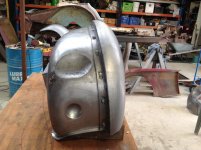
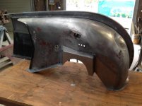
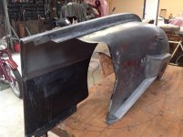
Finally got the left inner mudguard finished and added the cage nuts to both the mudguard and inner guard. Had to fabricate the box section that goes over the suspension turret and this had to be spot welded to the mudguard. Unlike the cage nuts along the edge of the inner guard, the location for the spot welds on the box section were in a fair way and deep, which the Eastwood type of spot welding clamp could not reach. After a bit of thought I modified my valve sprong compressor to make a clamp with the necessary reach.
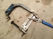
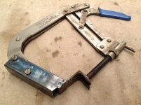
Worked well and will go into the tool kit for future use. When the need arises I will modify it so the foot can rotate through 90 degrees as I can see situations where it will be required.
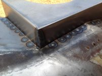
The wleds look like this.
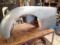
The mudguard and inner complete with their home made cage nuts looks like this.
Onwards and upwards. Next and final job is to fabricate a spare wheel carrier then I can start reassembly of the million parts to make a car!


Worked well and will go into the tool kit for future use. When the need arises I will modify it so the foot can rotate through 90 degrees as I can see situations where it will be required.
The wleds look like this.

The mudguard and inner complete with their home made cage nuts looks like this.


Onwards and upwards. Next and final job is to fabricate a spare wheel carrier then I can start reassembly of the million parts to make a car!
Frank Canale
Jedi Warrior
Offline
Thank you for the photos of your fuel tank, and the fabrication tips. When I find an old rusted out tank I will get started. there is little rush for I have a long way to go before I need the fuel tank. I have started on the passenger inner sill and floor. since I will be cutting the A post from the inner sill is there any down side to remove the A post to replace the hinge nuts with stainless nuts, re weld a cage nut, repair the bracket that the check strap attaches to. If I remove the A post I can also weld a crack at the slot on the scuttle behind the A post. This will make several repairs easier but want to make sure I am not going to make a problem down the road. I have fabricated brackets to re position the A post back exactly where it is incase I decide to remove it. Any advice is greatly appreciated, Frank
OP
LionelJrudd
Jedi Trainee
Offline
Hi Frank. It seems most people avoid separating the post if at all possible due to the difficulties realigning the posts, doors etc. Both A posts on my car were rusted through at the base so I have no option but to realign them in the future. If you have both the door and the corresponding front mudguard off, you should have reasonable access to the parts you mention. If the cages are still OK, you can replace the nuts by bending up the side of the cage and then bending them down again when you have swapped the nut. Several of the cage nuts on my A posts need to be replaced and I will be doing that with the posts attached to the scuttle which is separate from the sills and also the inner guards. Ie scuttle and A posts alone.
OP
LionelJrudd
Jedi Trainee
Offline
Frank, my apologies. Obviously I started typing without putting my brain into gear last night. Looking at the A post on my scuttle this morning it is obvious that getting to the cage nuts is not easy as I indicated. I forgot that I currently have the kick panels off mine and therefore I have access to the back of the A post. Quite a lot different to when it is on the car. If you are removing the kick panels from your car which you will need to do to remove the post, then you can access the back of the post. Still fiddly to weld in there.
If you leave the kick panels in place, then they attach the scuttle and firewall to the sill and will retain the relative positions. Just be sure to put the post back where you found it.
If you leave the kick panels in place, then they attach the scuttle and firewall to the sill and will retain the relative positions. Just be sure to put the post back where you found it.
Frank Canale
Jedi Warrior
Offline
Thank You for the thoughts. I am going to replace the bottom 2" of the kick panel that has the off set that welds to the inner sill. When I first looked at the cage nuts inside the A post I did not see a way to bend the tabs out to replace the nuts. Removing the A post will make three repairs much easier. I have had to slow down and do a lot of thinking and coming up with a plan of attack. Hope to get started back on it after the holiday( Thanksgiving). After seeing your post with photos I am going to try and start including photos as I work thru the process. I work full time so progress is slow. Thank you, Frank
I want to give a shout out to you Lionel and thank you for posting this thread. You are definitely an inspiration and truly a renaissance man. Didn't think I'd be interested in fabricating sheet metal (even started looking around for someone to fab me some repair panels), but I am inspired.
Thanks once again for sharing your journey with us.
Cheers,
Ron
Thanks once again for sharing your journey with us.
Cheers,
Ron
OP
LionelJrudd
Jedi Trainee
Offline
Thanks for the comments Ron. Had to ask my wife what a renaissance man is and we decided it must be good. Be encouraged to have a go at the fabrication. Got to start somewhere and the product will be totaly your own.
Decided to look back at the firewall I put together some time ago to finish off the detail. At the time I didn't have a satisfactory way to spot weld or a supply of cage nuts so the holes and cage nuts needed to be done. Likewise lots of holes for steering columns and the like had to be sorted to facilitate conversion from left to right hand drive.
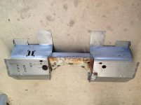
When I started to do the cut outs for the brake clutch assembly I decided to check the fit of the peddle box. Funny how time dulls your memory of the parts you have removed. I'm sure it was better than this when I took it off. Brings up the old question of refurbish or replace? I have decided the brake fluid container wil be replaced.
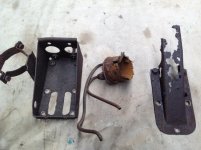
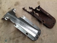
The supporting frame was a bit rusted so I decided to fabricate a new one. Made it from RHS which I had to cut down its length to adjust the width of the assembly from two inches to one and seven eigths inches. This was good because it allowed me to bend the flanges and then weld the two halves back together.
Unfortunately the peddle assembly was fused together with rust. The peddles pivot on a shaft which hangs in two bushes which are clamped in the frame. One bush turned in the peddle and the other was totally locked. Both bushes were eaten away with rust.
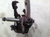
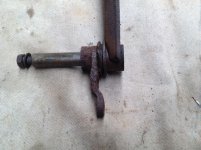
You can see the grooved bush between the peddle and the actuating lever. Unfortunately the bush is locked in place because the lever is welded on after the bush is put on the shaft. I decide I need to disassemble both peddles and replace the bushes. This required an angle grinder to cut the welds on the lever.
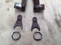
I turned up two new bushes on the lathe and then welded the levers back on the main bosses. Reassembled the peddles into the supporting frame. If you cross your eyes and squint you can see the new bushes between the peddles and the frame.
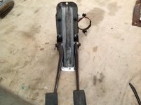
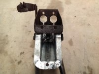
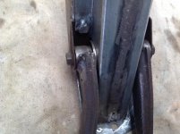
Finaly back to where I started from! Dry fitting the assembly to the firewall to ensure the holes are in the correct places.
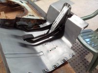
Two days work! Maybe I should have bought one!
now to get back to my firewall.
Decided to look back at the firewall I put together some time ago to finish off the detail. At the time I didn't have a satisfactory way to spot weld or a supply of cage nuts so the holes and cage nuts needed to be done. Likewise lots of holes for steering columns and the like had to be sorted to facilitate conversion from left to right hand drive.

When I started to do the cut outs for the brake clutch assembly I decided to check the fit of the peddle box. Funny how time dulls your memory of the parts you have removed. I'm sure it was better than this when I took it off. Brings up the old question of refurbish or replace? I have decided the brake fluid container wil be replaced.

The supporting frame was a bit rusted so I decided to fabricate a new one. Made it from RHS which I had to cut down its length to adjust the width of the assembly from two inches to one and seven eigths inches. This was good because it allowed me to bend the flanges and then weld the two halves back together.

Unfortunately the peddle assembly was fused together with rust. The peddles pivot on a shaft which hangs in two bushes which are clamped in the frame. One bush turned in the peddle and the other was totally locked. Both bushes were eaten away with rust.


You can see the grooved bush between the peddle and the actuating lever. Unfortunately the bush is locked in place because the lever is welded on after the bush is put on the shaft. I decide I need to disassemble both peddles and replace the bushes. This required an angle grinder to cut the welds on the lever.

I turned up two new bushes on the lathe and then welded the levers back on the main bosses. Reassembled the peddles into the supporting frame. If you cross your eyes and squint you can see the new bushes between the peddles and the frame.


Finaly back to where I started from! Dry fitting the assembly to the firewall to ensure the holes are in the correct places.

Two days work! Maybe I should have bought one!
now to get back to my firewall.
OP
LionelJrudd
Jedi Trainee
Offline
To continue the spot welding saga.
As they say about necessity and invention. I needed a way to spot weld the cage nuts that were in the middle of a panel where my clamps would not reach. The critical thing is that the two sheets of metal are firmly pressed together. Commercial wleding gear clamps and then weld in one process. Amateurs clamp and then weld. (Eg me) Day dreaming about how I would do them and came up with the following.
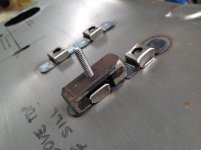
Two bits of heavy plate welded to a flat bar. The bar is threaded in the middle to take a gutter bolt that will pass through the cage nuts. When the bolt is tightened it holds the cage and nut in place and also acts as a heat sink for the spot weld. In the following photo you can see the head of the gutter bolt and the spots where welds have been completed. To the right are several cage nuts spot welded in place with the modified vice grips as these are near the edge of the sheet.
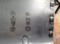
As they say about necessity and invention. I needed a way to spot weld the cage nuts that were in the middle of a panel where my clamps would not reach. The critical thing is that the two sheets of metal are firmly pressed together. Commercial wleding gear clamps and then weld in one process. Amateurs clamp and then weld. (Eg me) Day dreaming about how I would do them and came up with the following.

Two bits of heavy plate welded to a flat bar. The bar is threaded in the middle to take a gutter bolt that will pass through the cage nuts. When the bolt is tightened it holds the cage and nut in place and also acts as a heat sink for the spot weld. In the following photo you can see the head of the gutter bolt and the spots where welds have been completed. To the right are several cage nuts spot welded in place with the modified vice grips as these are near the edge of the sheet.

I have changed my mind about the water in Australia being the genius activator and decided it is the under sun effect/down under. Leonardo Da Vinci was a renaissance man. Heck I love that clap for the caged nuts. I took a fender that was a little thin and a store bought caged nut and spent most of my time blowing holes in the fender and some of the cage nuts that stuck feel off with a strong push.
Thanks for the tip on gas welding; that was probably the way they were done. I worked with guy that could weld that way and it looked great, but once and a while they would break, perhaps the penetration was poor.
Your tip is excellent about the A post as well because the inner kick panel has that straight edge that goes down onto the top of inner sill and sets the vertical position off the A post, IMO. Keep up the excellent work, but I have to say sometimes purchase some stuff of evilbay at least for a pattern, and please keep posting; it is better that TV.
Peace out steve
OP
LionelJrudd
Jedi Trainee
Offline
John I metal formed the stiffening ribs. Cut a piece of flat bar the appropriate tickness, width and rounded the ends. Clamped the sheet on top of it and then hammerformed the metal down with a drift and heavy ball pein hammer. Did this before I did the bends in the sheet.
Steve, its just rainwater here and lots of sun!
Lionel
Steve, its just rainwater here and lots of sun!
Lionel
OP
LionelJrudd
Jedi Trainee
Offline
As my old boss would say, Assume Nothing! When I was removing the inner mudguards from the firewall, the rusted state of the guards lead me to assume the box brackets that strengthened the attachment between the guard and firewall would be eaten out with rust inside. Accordingly I decided to simply cut off the flanges that were welded to the firewall, thinking I would have to fabricate new box sections. Of course Murphy's Law came into play and both brackets were nearly perfect inside. I have just spent some time re-making the flanges for the perfectly good box sections.
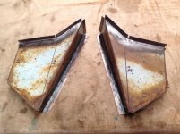
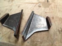
Some would say day dreaming though I call it dry fit up of the parts. This is what it looks like now!
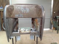
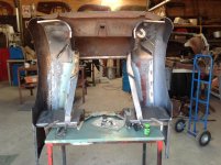
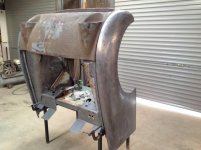
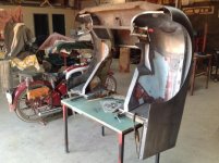
The front cowl is one of five I have. Still to decide which I will use. The bike in the background is my 47 Triumph Speedtwin.


Some would say day dreaming though I call it dry fit up of the parts. This is what it looks like now!


The front cowl is one of five I have. Still to decide which I will use. The bike in the background is my 47 Triumph Speedtwin.
This thread is the best example of positive thread drift ever - from the shape of the rear taillight opening to "how to make a car by hand". I will never be able to do any of this but its sure fun seeing it get done. John D did his great TR2 thread and he is being modest because his work is great too.
Dan
Dan
