• Hi Guest!
    You can help ensure that British Car Forum (BCF) continues to provide a great place to engage in the British car hobby! If you find BCF a beneficial community, please consider supporting our efforts with a subscription.

    There are some perks with a member upgrade!
    **Upgrade Now**
    (PS: Subscribers don't see this gawd-aweful banner
Tips
Tips

TR2/3/3A Rear tail light cutouts

Hi Lionel, I am having a little trouble forming the bottom 14” of the passenger mud guard (wing). I have made a buck that I copied the driver side from. The first attempt was close but not good enough. Did you use a shrinking stump or just a sand bag? I need to do the shrinking first to get the general shape. I thought I could do it with the English wheel but there is more shrinking than it looks like. Any help is greatly appreciated. You seem to be a natural metal worker. Great workmanship!!!!! Frank
 
Lionel,
Just to make sure you know, my comment about being a renaissance man is truly a compliment. I had feared that certain colloquialisms might be misconstrued. I forget that we here in the States didn't invent the English language, we just massacre it daily :wink-new:

To me, a renaissance man is someone of many talents, even some yet realized. Just because you might not know how to do something, it just means you haven't learned it yet. That is (to me) the mark of a true renaissance man. I would hazard to guess that you probably cook as well as sew, dabbled in woodworking and installed most of the lighting in your house. You'll fix the dishwasher yourself, rather than call a repairman (unless you truly have no time). You figure out how things work.

I can't wait to see how your TR comes out, but no pressure. Take breaks, enjoy some grilling with friends (it is Christmas after all, right?).

Did you see John's long posts (great how to) on his restore? I've read them 2x. There were a couple parts that I skipped over the first time (didn't think they were pertinent at the time but went back anyhow). So much info there and great pix as well.

Cheers!

Ron
 
Hi Frank, I guess we are talking about the rear wing. Unfortunately I didn't take enough photos of this work. Didn't realise it would create the interest it has. So the photos I have don't show the detail I would like.
The wing requires a combination of both stretching and shrinking but in the first instance is just a straight roll along the top shoulder and a straight roll down the back end, nearly at right angles to each other. I just rolled both over a length of about four inch pipe I clamped to the edge of my bench. The rolls get a bit crowded at the tail light area where they meet so I then went into some severe shrinking in that area to blend the rolls together. When I got the rough shape of the tail light section I then used the shrinker stretcher on the flat part of the section to pull that area in tight. You need to cut away any excess metal to simplify the shrinking. Once I had roughed out the shrink in that area, I then started stretching back into the body area on the sand bag to give it some body. You can see the "walnuts" in the photo below from the ball pein / blocking hammer.

IMG_1272.jpgIMG_1277.jpgIMG_1278.jpgIMG_1279.jpg

You need to be careful with the shrinking though. I always worry about getting enough shrink and then over do it. I find it harder to stretch the metal back nicely after too much shrink as the shrinking work hardens that area. So a bit at a time. The shrinking is done with a tuck fork to put tucks in the metal and then hammering in the shrink with a blocking hammer on a hard wood block. After work on the sandbag, I wheel it to check that the shape is forming correctly. Might then need some more hammer / sand bag work to continue getting the shape. Don't over do it though because the wheel will also add body to the shape without much pressure.

From there I used tucks and the hammer to shrink in the bottom corner a bit but not too much. I also used the hammer and sand bag to balloon out the back of that area a little, rolling it on the wheel to keep it smooth and allow me to see it taking the shape slowly.

The curvature of the back section is also determined by the rear flange. As soon as you put the flange on it, you stuff up the shape. Applies to the top section as well. The shape is recovered by shrinking / stretching the flange accordingly to bring the curvature back into the panel. The critical thing though is to not put any flanges in place until you have the shape fitting the buck. You play with the flange to recover the shape you have already put into the panel. (The exception is when you want a flange to lock in the shape. Eg hold the edge straight or to a pre determined curve)

Getting the rear bottom curve / corner right was done by shrinking the flange in that area to pull the rear edge in. I cut myself a little profile to match a good wing and then kept shrinking a little at a time and repeatedly checking against the profile until the bottom edge matched nicely.

It does not look like there is a lot of curvature in the panel but there is the same as the originals. Also, the final shaping will be done by tweeking the flages when the panel is fitted to the car.

I hope some of this makes sense. Happy for others to offer suggestions because I'm just finding out as I go. Would love other guidance that clarifies things to help Frank out and add to my small collection of techniques.

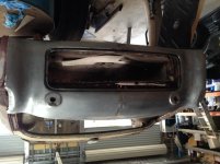
So Frank, keep at it but take it slowly. When I started the rear panel of the car, I walked away from it and it sat next to the car for about six months before I worked up the courage to go back to it. The final panel is the same piece of metal I started with. Sometimes you have to think about it a bit more and then give it another go. All you can do is lose a bit of time and a small sheet of metal.
Sat like this for months
IMG_1027.jpg

Ended up like this
IMG_1308.jpg
 

Attachments

  • IMG_1204.jpg
    IMG_1204.jpg
    63.7 KB · Views: 77
Ron, nothing misconstrued. My wife likes taking the micky out of me now referring to me as the renaisance man as a joke. We spend a lot of time in Indonesia and that's where you get cultural confusion. Got to be pretty laid back otherwise you spend all your time second guessing everything happening around you.

I'm really chuffed that people are enjoying what I am doing. Adds that little bit extra to banging away at one's own little hobby. Read John's work several times and still refferring back to it to see how some things go together. It's amazing how confusing little bits can be when the rust has eaten away that critical corner joint or all the section where the floor is supposed to attach to the firewall. I'm amazed at the attention to detail in John's work and documentation of the work. I get carried away wanting to see the next stage of what I am doing and before I know it, I have not photographed the work I have done. A case in question being my response to Frank above. I did two guards and don't have photos to show Frank the detail of the work. More attention to detail next time I guess.
regards,
Lionel
 
Hello Lionel

Working and photographing as you go is difficult. It is amazing how much you have got documented. I get carried away and forget the camera.

Looking forward to the next stage.

David
 
Work on the firewall and scuttle has stopped. Need to sand blast the A post area to install new cage nuts so I can proceed with fitting the kick panels. Need new air cleaners for the compressor which I have acquired so can't sand blast until I have them.
Decided after test fitting the front end that I will need to move ahead with the front cowl so when the rest is done, it will be available to fit. Checked the five cowls I have and one is better than the rest. Someone previously thought the same and there were piles of droppings from a MIG welder plus the obligatory bronzed patches. The front of the cowl has been worked with a shrinking or stretching hammer leaving an area of acne that I haven't decide whether I will have to cut and replace it as the pits left by the hammer have rust in them. The flanges on either side of the cowl have been bronzed at the cage nut locations to rectify cuts accross the bolt holes but most of the holes are torn still and will need to be replaced.
IMG_1463.jpg
In the above photo you can see the marks from the hammer. The area is stretched and will need replacing or at least shrinking. Below it on the lip you can see to the left a fracture in the lip which has been bronzed with the metal overlapped. I have marked this for removal and replacing the metal. Previously the panel appears to have been cleaned with a flapper disk or some other aggressive abrasive. The edges of flanges have been abraded and the metal thinned to the point of needing building up or replacing. Both sections where the bumper bar mounts pass through the panel will need to be replaced as the holes are torn and the mig weld that has been put around them has distorted the metal and is about 3/16 inch thick.

The flange on the right side is pretty ragged so I cut it off and then flattened the remaining metal in the lower half of the cowl. The reason for this is that previously the flange has been damaged and in reshaping it, the person has reduced the width of the front of the cowl. I checked the width against several of the other cowls.
IMG_1454.jpgIMG_1456.jpg
As can be seen from the above photo, the remaining metal is damaged so I cut back from the flange area about half an inch and then added enough metal to create a one eighth inch flange to match the un damaged section. I blocked the cowl up on the good section of the flange and used the bench top as a level to extend the line around the new metal to bend the new flange stub.
IMG_1457.jpgIMG_1458.jpg
Previously I made a template from my good mudguard to allow me to allign the repair sections on the damaged mudguard so it matched the good one. This profile is the same as the flange of the cowl so I was able to use it to draw the new flange outline. You can see the difference between the required profile and the cowl without its flange.
IMG_1459.jpgIMG_1460.jpg

Below are photos of the new flange tacked into position ready for the final seem weld and cage nuts to be attached. I left about one eighth inch flange to weld this to so the weld is on the flat of the flange and will not be visible when the mudguard is in position. Normally you would weld along the fold of the flange!
IMG_1461.jpgIMG_1462.jpg
Tomorrow hopefully I will complete the seam weld, attach the cage nuts and replace the dodgy sections on the flange on the other side
 
Your work continues to amaze me. Having several cowls was handy when you came to check dimensions.

I was lucky that my cowl was not too damaged or rusty.

Keep up the great work.

David
 
Finished the repairs to both flanges on the front cowl. Perhaps of interest is the effect of welding the flange in place. Given the flange was cut to match my template for the top profile of the mudguards, the photos below show the shrinkage and its rectification.

IMG_1467.jpg
The gap between the flange and template is about half an inch because the welding on the outer edge of the flange shrunk it, flattening out the curve.
Some gentle work around the inner edge with the shrinker brought it back into shape to match the profile.
IMG_1469.jpg
Each of the cage nuts was removed from the other flange and the ragged holes cut out. Per John Durant's edict the cutouts were curved to reduce stress. The bar accross the flange was to allow me to lock the curve of the cowl according to the template before cutting the patch pieces, reducing the chance of changing the shape by using the wrong sized patch. As an academic exercise I made the overall curvature of the cowl slightly larger to allow for shrinkage as I welded the patches in. This would be a matter of course for a boiler maker but a first effort for this amateur. As luck would have it, after the welds and its associated shrinkage, the curvature matched the template as good as perfect!
IMG_1470.jpgIMG_1471.jpgIMG_1472.jpg
Below is the test fit of the right mudguard to the new flange. The second photo shows the variation at the bottom of the cowl. The left mudguard is spot on but the right side of the cowl is about three eighths of an inch shorter than the guard. I am using a reference point at the back edge of the cowl which has been transferred to my template to ensure both sides match. No problem, I will adjust the fold lines at the bottom of the cowl and add a bit of metal if necessary on this side.
IMG_1474.jpgIMG_1475.jpgIMG_1476.jpg

Next job is to tidy up the "lips of the mouth" where a couple of fractures have been bronzed back together with the metal overlapped. Will have to cut out and put in new repair sections. Made up a dolly yesterday that will fit inside the lip to allow me to reprofile the lip which has been pummelled badly in the past.
 
As always, beautiful work, Lionel. It must be nice to be able to only repair an original panel, instead of beating from scratch!
 
John, new metal is a pleasure to work. There is something to be said for recovering a panel which otherwise might have ended up on the tip though. I still can't build any enthusiasm for rectifying previous owner's repairs. I understand we do what we can with what we have available at times just to keep a vehicle going. Maybe I'm getting a bit precious these days. But there is nothing quite like the feel of welding fresh clean metal.
 
Finally got to try the grill in the front apron today. Had to cut out previous repairs to the lip of the mouth and put in new metal. Made a dolly the other day for rolling the top lip and it worked fine. The lip had been crushed as well as having sections of the metal thinned by agressive sanding. I think the paint might have been removed with a flapper disk previously and in the process, the surface is scored in many places and corners of the side flanges ground away to the point where they needed to be replaced or built up with weld.
When I first presented the grill to the apron, there was no way it would fit in the opening. After working the shape back into the apron, the mouth was opened up and the grill fitted back in. Had to tweek the edges of the aluminium grill a little to seat down against the apron but early stages yet. Still a lot of tidying up to do on the apron but ran out of argon today!
not sure what the flat section in the bottom of the mouth is called but had to cut out the area where the crank handle bracket mounts. The pressed section needed new flanges made and the middle of the flat section had to be replaced to receive the pressing. When I have some gas, will finish the flanges on the pressing and then spot it into place.
IMG_1483.jpg
Shopping for gas in the next day or so!

GrahamH lent me a pattern for the high low beam switch so in a slow moment the other day made a right hand drive mounting bracket for the switch. Added some seam welds and an e tra gusset to strengthen it up a bit.
IMG_1480.jpgIMG_1481.jpg
 
Looks the part Lionel, youre grill looks like an original with the wider air slots?they must be getting rare these days?

Graham
 
Hi Lionel, decided to give myself a few Christmas presents today. I ordered David Gardiner's DVD on metal shaping with hand tools. I am fond of the Picard line of hammers and was going to order an embossing hammer but was not sure what size to order. I was going back thru your pictures of the rear mud guard and noticed you have a hammer like i am looking at. What size embossing hammer are you using to do your metal shaping? I will be making my tuck fork this week in preparation for time off between Christmas and New Year. Thanks, Frank
 
Graham, I'm wasn't aware there are different types. The one I've got is the only one I have so that's it for the car. A bit dog eared but for now it will fill the hole.

Frank, good to have Christmas plans. I have no idea of the size of my hammers. Went to a shop that sells panel beating tools and went by size, weight and quality. Don't even know their brands. Reckoned I would need to hold them for some time so they better be comfortable. I think the best bet is to buy the minimal number of tools. Then add when you see a real need that shows up from the work you are doing. Also use what you have available. I have a basic set of dollys that I bought at a swap meet. I make dollys / stakes out of bits of galvanised water pipe, offcuts of steel beams left over from building my house. Also picked up some tools that would have originally been used by water tank fabricators for rolling over seems in the tank. Can't say how many times I have used them but they get used most days. Got each one for a dollar each. Don't waste money on fancy stuff. Have a great Christmas with your toys!
 
By way of avoidance, I was looking through my pile of bits and pieces for the car. The doors caught my attention and I remembered there is a capping that goes on the top of the doors as the base for the padding and vinyl on top of the door. One door has the remains of the capping and it is missing totally from the other door.
My sample capping! A bit ragged.
IMG_1485.jpgIMG_1486.jpg
Thought about how to make the shape and found I had a stake that matched the diameter of the depression in the channel. The stake is one I made from a water pipe bend a while back. I made a matching dolly / die from a smaller diameter piece of pipe to work the inside of the capping.
IMG_1487.jpgIMG_1488.jpg
I bent a channel to match the capping with a bit extra width to allow for a reduction in width as the depression is formed.
IMG_1489.jpg
Hammering the top die into the channel in the jaws of the vice allows the depression to form while the jaws of the vice stop the sides of the channel splaying out. A result of this is the channel also starts to curve as required to fit the top shape of the door.
Below is the channel as it came out of the vice. Not fully curved but getting there. A little bit of work with the shrinker / stretcher on the outer edge of the flanges brought the curve around to match the original.
IMG_1484.jpg

IMG_1490.jpgIMG_1491.jpg
Very happy with the way it turned out. Still got to add the little end cap for the ruuber padding but will do that when I have some gas for the tig.

What I don't know is the shape of the rear end of the channel. This bit was totally rusted away on my sample so I just made the channel long enough to extend past the back of the door for now.

Anyone out there who can provide a picture of the rear end of the channel?

Guess I will have to make another for the passenger door if I want my wife to ride with me!
 
Hello Lionel

Great work. Making good use of what you have to hand.

I took the easy way out and bought new ones.

Hope these photos help.

David
Door cap trim.jpg
Door cap trim 2.jpg
Door cap trim complete.jpg
 
Had a go at the little caps at the end of the door cappling today. Turned a piece of hollow steel to match the inside diameter of the caps and then found a hollow section just larger than the outside of the cap to use as a drift. I rounded over the inner edge of the drift so when it is driven down on the metal, it didn't dig into the metal.

Cut four circles of sheetmetal large enough to accommodat the diameter of the cap and the side edge of the cap. Mounted the circle on the hollow section with some washers and a bolt and set it up in my vice.
IMG_1495.jpgIMG_1496.jpg

Gently worked the outer edge down with a small hammer to start the shape of the cap. Then started drifting down over the mushroom to form the shape. Alternated between using a small hammer working the metal down and in and drifting with a bigger hammer. I put a little oil on the metal when using the drift to assist in the drift sliding down over the metal.
IMG_1499.jpgIMG_1500.jpgIMG_1501.jpg
I then mounted the assembly in my lathe to part off the rough end so the cap would be left the correct length. This could have been done with snips or a saw but the lathe is available to me and set up for the job. While still in the lathe, I dressed the cap with emery paper.
IMG_1497.jpg
Caps look like this and mount to the door capping like this. I seam welded the edge of the cap with the tig as there is not enough metal to safely spot weld per the other bits I have been doing.
IMG_1502.jpgIMG_1504.jpg
 
Hello Lionel

Looks better than the bought caps.

I noticed that when I put my door capping on the door the front pointed tip does not line up with the dash cap. The points are lower. Not sure if the dash cap is too high or if I need to trim the door trim.

David
 
Back
Top