• Hi Guest!
    You can help ensure that British Car Forum (BCF) continues to provide a great place to engage in the British car hobby! If you find BCF a beneficial community, please consider supporting our efforts with a subscription.

    There are some perks with a member upgrade!
    **Upgrade Now**
    (PS: Subscribers don't see this gawd-aweful banner
Tips
Tips

TR2/3/3A Rear tail light cutouts

Hi lionel,
Glad to see the New Year has brought you positive progress. I too see you completing the tub way before the year ends. I have taken your advice to go slow on my patch panel for the passenger rear wing where the stone guard covers. I have the patch to the point where it matches the driver side. Now the task of forming the flanges, sure would hate to loose the part after this much work. Did you use a tipping die on your bead roller to start forming the flange or just a hammer and dolly. I have enjoyed working on this part, it seemed to fight me over and over till it finally gave up and started to work right into the shape i wanted. Thank you for you help and continued success . Frank
 

Attachments

  • IMG_0164.jpg
    IMG_0164.jpg
    47.6 KB · Views: 93
Hi Frank. Looking good!
I used the bead roller with my tipping die as I was doing half a guard at a time. On smaller sections I will / have simply worked the flange over on a sharp edge held in the vice, taking care to follow the line carefully.
When you do, the flange it will affect the curvature of your main piece as it will be trying to fit back into a smaller radius and therefore flatten out the main curvature. Consequently you will need to shrink the flange a little to regain the correct curvature. I often alternate tipping and shrinking until I achieve the correct angle of the flange and also have retained the correct curvature of the panel.
Easier to creep up slowly on the correct angle / curvature combination than to have to try and stretch the flange back out again because you went too far.

Tacked the front inner guards onto the firewall today. Started to do the final seam welds and messed them up. Couldn't seem to make a good weld to save myself. Went for a ride on my bike to clear my head and then decided to start on something else. The final welds can wait until I make a rotissarie and can turn the body over.

So now, the back half of the car is going together! Started detailing the front rear floor pan with the cage nuts and access holes ready to install it. 2019 moves along!

Keep us posted on your panel.
 
Waiting with baited (bated?) breath Lionel. Love looking in on you and seeing where you are at.

Happy New year (a bit late, but I've been putting in the overtime to afford this hobby).
 
Had a look at the channels that run down either side of the boot compartment. They had attracted my attention while I was documenting some reference measurements for when I start rebuilding the rear half of the car.

Some time ago I made the sections but did not assemble the channels as I was not sure how I was going to weld it together. Now I can spot weld with the tig, the issue was resolved.

I clamped the two sections together with some bits of steel to set the width of the gap in which the rubber seal will sit later. I used a heavy piece of steel to back the welds as a heat sink. This was clamped in place by my spot weld clamp.
View from the clamping side and view from the welding side.
IMG_1548.jpgIMG_1547.jpg
Finished channe. Ends will be mitred and cut to length when fitted to the car.
IMG_1550.jpg
Clamped to the rear side panel of the boot. Made the sode panels some time ago and they have been sitting in my store room waiting for this year.
IMG_1549.jpg
 
Finally bit the bullet today and started on the rear end of the car. Had spent a lot of time sitting thinking about the order in which panels needed to be replaced so I could retain the integrity of the structure. Decided in the end to make sure I have enough measurements documented so I can check the dimensions as it goes back together and then just start.

Went to put the rear floor section in and then realised that it is an under and over part. The flange on the prop shaft tunnel goes under the front floor pans and the flange at the back goes over the floor pans. Could not get it in place as the front pans are spot welded in place and the rear of the car didn't allow enough room to slide the section in from the back. Lifted the rear tub off with the block and tackle and pushed it out of the way. I had built a gantry over the car so I could lift the tubs and chassis up onto stands. With the rear tub out of the way, there was enough wriggle room to fit the rear floor pan.
Removed the wheel arch
IMG_1552.jpgIMG_1553.jpg
Put in the one I made in June 2017. I made these wheel arches first after the flat panels as they were the simplest sections to practice my metal shrinking with a hammer and block of wood. Also simple to practice on the English wheel. The arch was made in three sections and then tigged together. The main flat section with a rolled outer edge, two sections around the circumference with a rolled edge to butt up against the flat section. These two also had the flange tipped on their outer edge. When I made them, I approximated the angle of the flange. Now they can be put in situ, I will tweak the angle of the flange using the shrinker / stretcher. Once it fits nice, I will then mark and cut the holes for the cage nuts.
IMG_1554.jpgIMG_1555.jpg

No progress tomorrow. Got to go to the city for the day.
 
Tweaking the shape of the rear wheel arch today and it occurred to me that if I put the arch in place, I will not be able to reach into the centre of the floor plan to spot weld the boot floor to the middle floor pan. Likewise, I will not be able to reach in and spot weld the front of the spare wheel carrier to the boot floor.

Finally decided to remove all the upper part of the rear half and put it aside. Using the rear mounting points for the body on the chassis as reference points I will build forward to the doors and the rear end of the outer sill.

So I removed the rear apron, cut around the wheel carrier and drilled out the passenger side wheel arch.
IMG_1556.jpgIMG_1557.jpg
You can see why I had to make a new rear apron!

Once freed, I lifted off the rear tub and then the spare wheel carrier and associated mounting brackets.
IMG_1558.jpgIMG_1560.jpgIMG_1561.jpg
The boot floor needs to be replaced. I have the correct panel from KAS.
All the minor panels associated with the rear of the car are beyond re-use. Some I made in 2017 in anticipation of today. These were really practice opportunities.
IMG_0943.jpgIMG_0955.jpgIMG_0953.jpg
As an aside, I did not know what the holes were for in the above curved pieces but decided since they were there, I should include them for authenticity. Only last year when I was looking at GrahamH's car did I learn that they are for the drain hoses from the water channel around the boot lid.

So today I started to fabricate the rear parts to create the base on which to rebuild the rear. The two black sections below are from Kilmartin Automotive Sheetmetal. Bought them in about 2009. Interesting in that the top flange on them was to the front of the car, not the rear as in my original panels. Not sure if this changed during the production changes but I reversed it to match my original panel.
IMG_1559.jpg
I removed the bracket which bolts the body to the chassis from the wheel carrier because they will be welded to the above section, but decided they are too rusted to re-use.

So tomorrow I will make the brackets, weld them to the above section and I have my base line to start rebuilding the rear tub.
 
Lionel you have definatly started from scratch with the rear end?you may need to do some reaserch on the inner tubes for the overider mounts that go through the rear apron, i see you still have one on the remains of your old apron. They would have been seam welded top and bottom to keep the elements out but were probably a place for the rott to start and i see Moss don't do the inner distance tube any more but a modified SS bolt.

I didn't realise you had had the beast that long, good to see so much progress now.

Graham
 
Wait a minute...you bought the boot floor?? Compared to what you have fabricated so far, I would think that would be only an afternoon job for you. Of course I am kidding. Still amazed at how many panels you have fashioned from sheet!
 
Hi Lionel. I comforts me to see you bringing out pieces you made in the past to start putting your tub back together. I too have an order with Kilmartin sheetmetal. I ordered the butter sills because the are the only company to make the ouster sill with the bow in them to mach the doors of the post ts60000 cars. My metal forming skills need work so I have decided to tackle the chassis so I don't get bogged down with body panels. My spare wheel carrier is ok minor patches where the body mounts rusted thru the tub and po patched and will need redoing. I will need to make a boot floor rather than patch the holes. I have the new rear body mounts fabricated so I will be working on the rear of mine as you are. My biggest challenge will be the quarter panel( dog leg ) both sides have rusted away so I don't have much to go by. That will be down the road. this is a picture of the blank i used to make the body mounts for my car I am not sure if they are the same as yours but thought it might help.
 

Attachments

  • IMG_0169.jpg
    IMG_0169.jpg
    53.3 KB · Views: 73
John, a long time ago in a land far away I had a job and was paid money. With not much time and a little bit of money, I frittered it away on car and motorcycle parts, some of which are now coming to light. Even then, I couldn't reconcile what I would have to pay for the more complex parts. Now with minimal money and an excess of time, the roles are reversed and unfortunately the complex parts are still required for the car.

Frank, good to be able to compare notes. Sounds like you are doing it section by section which it seems is the tried and true way to keep the integrity of the body. Coincidently, I made the body mounts today and attached them to the front panel of the rear box section below the apron. As mentioned above, this is so I can use the mounting holes as a reference point to build forward.
IMG_1565.jpgIMG_1564.jpg
Added the rear apron just so I could have a look. I spend a lot of time just looking!
IMG_1562.jpgIMG_1563.jpg
It seems there is a particular order to assemble the parts that allows the spot welder to access each part. I am working out the order as I go and keep checking ahead to ensure I will be able to access the necessary locations. Even so it can be a bit difficult because I do not have the reach of the large commercial welders used in assembly lines, and have to improvise a bit.

Next step is the spare wheel carrier so I marked out the base of the carrier. Will do this in three parts. The base and left and right sides. The wall of the carrier is really quite long when you measure it and would be a bit cumbersome to do in one piece so will do in halves and join together at the front, then weld to the base.

I did the preliminary pressing of the floor panel in the bead roller. Would have been nice to metal form the pressings but they are all different on one side so fudged it with the bead roller and then hammered the corners. A bit rough but when painted and a spare wheel covers it up, only the mechanic under the hoist will see it.... So sack me!

Next, the depression in the middle and then the rolled outer circumference. Some dodgy bits to do at the front edge so will think about them later!
IMG_1566.jpg
 
Hello Frank

I wish I had known that about 12 months ago. My outer sills were put on by the PO and needed a lot of work to look OK. Several times I almost bought a new pair but thought that I would probable not be much further ahead.

David

Hi Lionel. I comforts me to see you bringing out pieces you made in the past to start putting your tub back together. I too have an order with Kilmartin sheetmetal. I ordered the butter sills because the are the only company to make the ouster sill with the bow in them to mach the doors of the post ts60000 cars. My metal forming skills need work so I have decided to tackle the chassis so I don't get bogged down with body panels. My spare wheel carrier is ok minor patches where the body mounts rusted thru the tub and po patched and will need redoing. I will need to make a boot floor rather than patch the holes. I have the new rear body mounts fabricated so I will be working on the rear of mine as you are. My biggest challenge will be the quarter panel( dog leg ) both sides have rusted away so I don't have much to go by. That will be down the road. this is a picture of the blank i used to make the body mounts for my car I am not sure if they are the same as yours but thought it might help.
 
Graham, haven't got to them yet. Will do them last before I afix the lower box section to the apron and when I have it all on the chassis for alignment. Still got to make the base of the box section which fixes the bottom lip of the apron to the box but will do that when I have finally tweaked the curvature of the apron. Will work from the bracket holes in the chassis back through the box section to the apron, using some measurements from the old apron to guide the way.

If OK with you, I might prevail on you to come and have a look at your car again before I finalise this bit.
 
This one is for you Frank!
Proceeded with the base of the spare wheel carrier. To do the depression in the base, I drew a circle at the limit of the depression. At this stage I did not worry about the depression which extends to the rear opening, the idea being to get a uniform depression in place and then extend it rearwards when happy with the depth and quality of the work.

Hammered out the depression on the sand bag and then tidied it up on the English wheel. Then back to the sand bag and with the blocking hammer I extended the depression as far back as needed. Tidied this up on the wheel.

The rear lip where it joins the apron is depressed accross the width of the panel and there is a secondary depression in the middle for a tie down for the wheel. (I think). These I formed with the hammer and dollys and a couple of old bolts modified as punches. The outer edges were abused in the bench vice as well. (Those of you who know your wheel carriers will have spotted that the rear depression could be a little wider to fit the curved profile of the box section that goes under it. This has been noted and will be attended to!)
IMG_1567.jpgIMG_1568.jpg
Decided in for a penny, in for a pound and moved on to the rolled edge on the outer perimeter.
Marked the depth of the curve around the perimeter and then used the tuck fork to put a series of puckers around the perimeter. Hammered these out on the wooden block to shrink the outer edge.
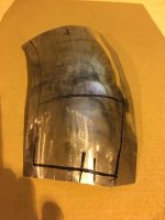
This is how it looked straight off the block. Not pretty but the curve was there.
IMG_1569.jpg
I have a stake made from a piece of one inch galvanised pipe which suited the curve here so I tidied up the curve on the stake. In rolling the edge over the stake, there was a tendancy for puckers to form naturally on the outside of the curve. These I worked back into the metal on the stake improving the shrink on the roll.
This is how it came off the stake. At the time I also rolled over the straight sides to the rear as these did not require shrinking. I also tidied up any walnuts in the metal where I may have mis-hit when trying to do the shrinking. (I guess it was me)
IMG_1570.jpg
About this point I decided it was time to move to the English wheel and roll it into a perfect curve. Ufortunately when I checked, I don't have any wheels that are tight enough radius to fit in the rolled edge.
So, hammer and dolly it is. I used the pipe stake as a hand dolly and proceeded to work the edge around with a panel hammer. This formed some more puckers naturally as I worked the metal into the curve so I put the stake back in the vice and worked the puckers back into the metal.
When happy with that, I found a dolly in my box of bits that fitted the rolled curve perfectly on the old spare wheel carrier. I worked around the perimeter with the hammer and dolly to finish it to the point where it can be welded to the wall sections. If you check the photo below, you will see there is virtually no sign of the puckers in the edge of the metal which shows what can be done with the basic tools.
IMG_1571.jpgIMG_1572.jpg
I still have to roll the sides at the rear of the panel where it protrudes through the rear apron. This is a different radius to the major perimeter roll. Also, the height of the rolled edge now needs to be scribed and trimmed, ready to accept the walls of the carrier.
 
Hi Lionel, Thank you for the lesson on metal forming, I can use all the help I can get. Spent last night looking at the back section and your influence on me has help me decide to stop patching and start making panels. The upper closing panel that extends onto the inner fender and includes half of the rear tail light will be the start. looks like a good panel to learn on. lower rear valance needs a repair as well as the panels you bought from Kilmartin. Lots of work but I am determined to learn this skill, It might take a few sheets of metal but I am going to get it. Off to work now , Thanks for the help.

Frank
 
You're welcome Frank.
Started off today by widening the depression at the back of the spare wheel carrier so it matched the profile of the lower box section. Basically just some hammer work on the sandbag and then using the planishing hammer and dolly to smooth it out.

I then started on the sides of the carrier. Did this in halves by putting a flange on one edge by rolling the metal around some 3/8 th rod.
IMG_1574.jpg
Those of you who have been paying attention will notice the bending instructions on one of the pieces is wrong. One should be a mirror image of the other! Luckily this was noticed before I started stretching any metal. There is a straight section and then the part which curves around the wheel carrier. By stretching the flange, the panel curves around. I stretched it gently along it's length, matching it against the old carrier to get the correct curve.
IMG_1575.jpg
In the photo above you may see the black line parallel to the plain edge. This is a guide line from which I will roll the edge inwards to match up with the outer rolled edge on the base. This edge will need to shrink. I did this on my trusty water pipe stake as per the approach for the rolled edge of the base.

Once the edges were complete, I set the height of the side on the base and scribed a line around the rolled edge of the base and trimmed. Set the sides on the base and tacked in place.
IMG_1576.jpgIMG_1577.jpg
Super happy with this! Even sits flat on the bench.
Next, seam welds, rear strengthener at the back of the carrier and then spot weld to the mounting brackets.
 
Back
Top