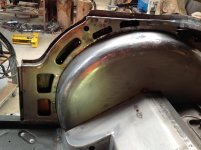
• Hi Guest!
    You can help ensure that British Car Forum (BCF) continues to provide a great place to engage in the British car hobby! If you find BCF a beneficial community, please consider supporting our efforts with a subscription.

    There are some perks with a member upgrade!
    **Upgrade Now**
    (PS: Subscribers don't see this gawd-aweful banner
Tips
Tips

TR2/3/3A Rear tail light cutouts

OK. Will proceed with tonight's installment.
Repositioned the rear body work and then decide to continue as I have been, working from the rear forward.
Cut out the flat pieces that go behind the tail lights and spot welded them in place.
IMG_1613.jpg
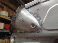
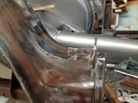
Added the little curved bits behind the tail lights to the side panels and the spotted that to the tail light mounting
IMG_1614.jpg

IMG_1612.jpg
and spot welded along under the side panel where it meets the side flange of the boot floor.
IMG_1615.jpg
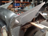
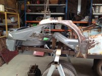
Repositioned the body work (that remains) to check distances etc.
IMG_1616.jpg
 
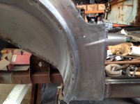
Have been tossing up what to do with the inside panels behind the B posts.
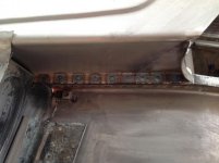
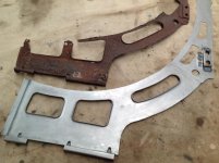
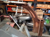
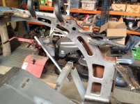
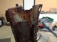
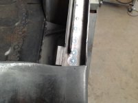
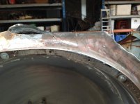
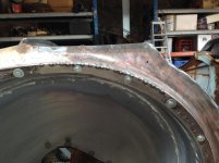
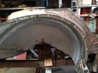
This is what one looks like. The other is much worse. The top of the inner panel is OK on one side but the other has rust in the top as well.
IMG_0866.jpg
Decided to remove the inner face of each side and replace it. May actually replace the upper surface as well but will decide that once I have made the inner faces.
Currently the inner mudguards are removed from this area. This is an older photo.
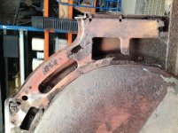
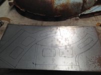
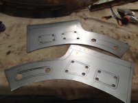
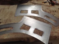
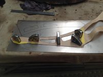
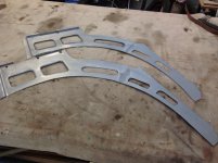
Took a pattern of the inner face and transferred to sheet.
IMG_1617.jpg
Cut out and drilled to remove the blank sections.
IMG_1618.jpgIMG_1619.jpg

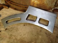
Started to roll the edges of the cut outs on a stake in the vice.
IMG_1620.jpg
The 1 1/2inch allowance at the top of the last photo is to create the channel where the upholstery tacking board goes.
The allowance on the right edge is where the flange of this panel goes down over the sill.
To the left will be attached some more sheet where the panel extends to the rear below the tonneau. This bit is just a flat cut out and I didn't want to waste a large sheet so made it in two parts.
Will comtinue tomorrow
Lionel
 
Hi Lionel, looking great. very nice bead work. Did you make your boot floor? I am going to have to make mine but I will have plenty of time to think it thru as I will be focusing on my spring tower / lower fulcrum pin replacement. Thank you for your pictures as this is where I will be headed in the near future. Frank
 
Are you sure you did not purchase a shell of iron oxide. I think I heard you say you have not worked with sheet metal much before, amazing. When I was 20, I worked at local sheet-metal shop, but we did mostly rain gutters and flashings for houses. I did cut and bend a lot of metal, so I am good with snips, but none of it was radiuses. In the State I live in the metal around the Vin needs to be original if you go through a title inspection, but they get fooled often. I would love to take your car in and watch them figure out where it starts and stops as original.
steve
 
Lionel, don't forget the striker plate and support bracket for the boot lock inside the rear valence it's a bit tricky to get at once it's all together.

Graham
P1010093.jpg
 
Hi Frank. I bought the boot floor from KAS back in 2009. Been sitting in the shed waiting for it's day in the sunshine. If I didn't have it today, I would make it. With the number of pressings in the boot floor, you will need to compensate for stretching and consequent warping of the panel. Even the one from KAS had some twist in it but this was overcome with some gentle persuasion and welding it to the spare wheel carrier.

Steve, western Australia is the iron oxide capital of Australia and we have exported half our state to China. If I had sold my TR on the open market, there would have been a dive in the price of iron ore! My background is in teaching science and then in IT. Just got to have the interest!

Graham, those bits are some of the things I need to look at on your car because they are non-existant on mine. Some things I can ad lib but others I really need to see an original example.

Today I finished off the inner panels. Still not decided if I will make the top sections for them or use existing.
Transferred pattern to sheet.
IMG_1621.jpg
After cutting out, tig welded the two halves together.
IMG_1624.jpg
 
Last edited:
Added the cage for the plate that holds the hood lower mounting point bolts. Punched out the little tabs for holding the tack strip for upholstery with an impact driver tip that I ground to shape on bench grinder.
IMG_1625.jpg
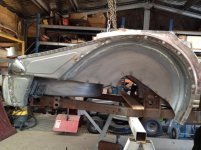
Cut out the old metal from the body. At this stage, the interior still needs cleaning.
IMG_1659.jpg
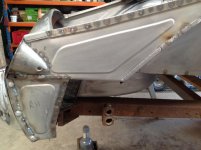
New section clamped in place. Top edge shows allowance for trimming to fit into existing panel. The inner curve has been checked against the inner mudguard for correct curvature.
IMG_1626.jpg
 
That looks great. You can't buy those pieces even if you wanted to.

I notice in photo 2 you can see where they got some paint on the in side of the dog leg panel.

David
 
They don't take that much time to make without the top flange. I would have to weld the flange on if I wanted it but since I have checked inside the dog leg they seem robust enough so will use the original with some minor repairs.

Moss list the inner panels but flag them as limited supply. It looks like their panels have the top flange welded on rather than a pressing. They also do not have the tabs for holding the tack strips, the cages for the hood sticks mounting point or the cut out for the door striker plate.

The paint on the panels appears to be over spray of red oxide primer, only where it has passed through the cut outs. Some sections inside the dog leg have a black primer on them. I have seen the same primer in other hidden areas of panels on the car.

Next job is to weld them in place. Not sure whether I will then do the gutter around the top of the boot opening to stiffen it up or start fitting the inner wheel arches. Might do the gutters first while I can still take the rear section off and get underneath where they attach to the tonneau to complete the welds. I hate trying to weld upside down!
 
Working on this car is like a moving feast. Never sure where you will be next!

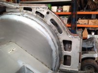
Thought some more about the order of assembley and realised I will have difficulty welding the inner wheel arch in place if I reinstall the inner wall of the dog leg. It would get in the way of my clamps when I am trying to spot weld the flange of the arch to the flange of the dog leg. So decided to move ahead with the installation of the wheel arch regardless of anything I have said previously.

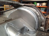
Added the flange for the inner panel to the arch and then clamped the arch in place to transfer the positions of the cage nuts to the arch. Welded them in place.
IMG_1663.jpg
Test fit holding in place with the rear mudguard bolts.
IMG_1660.jpgIMG_1661.jpg
With the inner guard in place it was possible to check the distances / position of the rear apron and boot assembly in relation to the front half of the floor so I could join the front and rear permanently. All OK.
Finally, a full length car, albeit with some parts missing!
IMG_1665.jpg
While the doglegs and tonneau were off the car, I decided it would be apprporiate to do repairs on the quarter panels and B posts.
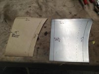
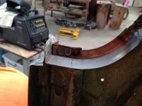
Started with a template of the lower quarter panel that all TR owners seem to know and love! Decided to have a go at a one piece repair section rather than the two piece approach many take. Just for the challenge.

The offending section (upside down)
IMG_1669.jpg

Pattern
IMG_1666.jpg
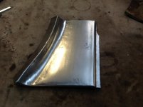
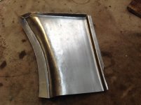
Worked out OK after some back and forth. Now know how to do it easier for the second
IMG_1670.jpgIMG_1671.jpg
Happy with that although it still has to be planished and surface finished.
For those interested, I will go through the fabrication process in detail when I do the section for the other side.
 
Hi Lionel, very impressive. As I suspected looks like you are ahead of schedule. Can’t wait to get back to the Sheetmetal work I have to do, some of what you have done to the back of your car. Straightening my frame now and then to repairing front suspension. Lots of measuring with nothing very interesting to post for now but the suspension part will be documented. I was incouraged to hear that you feel the quarter panels will be an easy part to form. Keep up the great work. Frank
 
Sorry Frank, I didn't say they are easy to form. I said having done one, the second will be easier! Still, they are not so bad. My comment related to knowing in retrospect what I should have done to get the correct curve in the section. Will explain when I do the second section.

Repaired the lower sections of the B posts and then refitted to car. The saga of the cage nut continues. Would you believe it after all the nuts I have welded on the car, I have welded the LAST one on and I was one short. Ran out of nuts a little while ago but recovered enough from panels to complete the job. Made the last cage by hand. If I had noticed when counting the six nuts in the spare wheel carrier and taken them into account, there would not have been a shortage. Live and learn!

Today I finished attaching the wheel arches and doing the final welding on the rear apron and side panels. I had a celebratory beer because now I have a complete body tub again.
IMG_1676.jpg
Very happy with this. When I recorded heights and diagonals from original, ther were significant discrepencies between the left and right sides. I have been able to reassemble and all measurements now are within two millimetres for the rear body. I installed the boot lid to check the opening is appropriate as well.
IMG_1683.jpg

IMG_1680.jpg
Had to install the gutter along the sides of the boot opening at this stage while I could get at some areas. Still need to finish this when I can turn the body on its side. Haven't done the section accross the rear apron and will look at that soon so I can sign off the rear end of the car.
IMG_1679.jpgIMG_1685.jpg
Now have to replace the flange on the quarter panel before I can do the final spot welds around the wheel arch.
IMG_1682.jpgIMG_1681.jpg
Once the flange and spot welds are done, I can weld the new inner quarter panels and then finalise the outer patch panels.
 
Really impressive work Lionel. Thanks for sharing.

Cheers,
Tush
 
Lionel:
I was just whining and crying over the sorry state of my original LH wing/fender wondering what I was going to do. The task looked insurmountable to me and was very discouraged.

I re-read your posts and feel a little more energized. I especially liked (re-liked) your re-fabrication of the front wing, notably, the flange. That may have saved me from an ensuing mental breakdown.

Thank you so much for sharing your journey!
 
Hi Lionel, I know that nothing Is easy but I understand what you meant as I have found on my frame. Non of it is easy but the second time is easier as I know what to cut and how pieces are formed. I am also not afraid of messing it up. It must be a great feeling of accomplishment to see the tub all back together. You have raised the skill level bar pretty high. I know it is making me try harder to make my parts better. Thank you for the documentation of your work so I will be able to go back and see how you did a panel. This will make it easier for me. Keep up the great work, Frank
 
Finally got back to the bodywork yesterday. Ran out of gas last week so got distracted cleaning and refurbing engine parts to fill in time and then got distracted by brakes and front suspension parts. Amazing how much time you can spend just cleaning and prepping for paint.

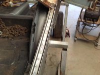
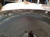
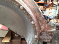
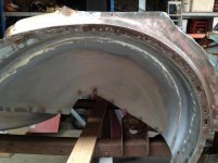
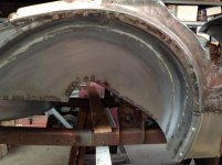
Decided I had better have a go at the outer flanges for the rear wheel arches. The inner tub is in place so I decided to cut the flange off in three sections, keeping two sections bolted in place to hold the outer skin and inner tub relative to each other. The new section would be tacked in place and rebolted, then the next section cut out. I left the full weld to the end so that any flexing of the flanges to sit in place could occur. Once all sections were in place and bolted up tight, I would do the final weld.
IMG_1698.jpgIMG_1699.jpgIMG_1700.jpgIMG_1701.jpg

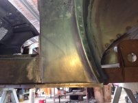
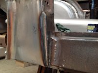
Went ahead with the patch panel in the lower front dog leg.
Added the bottom flange so it can be welded to the sill, sprayed some weld thru primer on and tacked in place.
IMG_1703.jpgIMG_1704.jpgIMG_1702.jpgIMG_1705.jpg

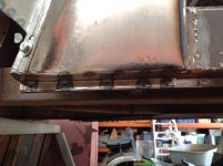
Spot welded to the sill and seam welded down the front edge.
IMG_1706.jpgIMG_1707.jpg

Still got to finish the panel weld and do some more spot welds around the flange but decided that was enough for today.
IMG_1709.jpg
 
Finished of the right hand side today. Had some rust in the top section of the quarter panel so cut that out and replaced the inner section then the outer skin.
IMG_1710.jpgIMG_1712.jpgIMG_1714.jpg
Installed the inner section of the quarter panel. Seam welded around the top edge and spot welded to the flange on the inner wheel arch.
IMG_1715.jpg
Now to do the other side.
 
Finally replaced the flange around the rear wheel arch on the left side and spot welded the inner wheel arch to the flange.

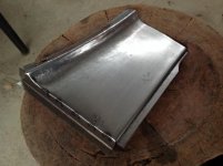
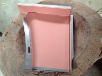
Previously, I said I would show in more detail the fabrication of the one piece patch panel for the lower front of the dog leg.

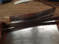
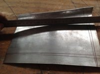
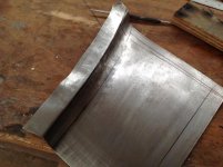
The section has a slight curve in its in its main area both horizontaly and vertically. If the curvature leading to the flange is created from a flat section, a resulting depression will result in the panel. To minimise this effect, the flat section needs to be pre-curved prior to creating the outward curvature. I did this on the English wheel but it could have easily been done with a round mallet on a sandbag. The two black lines are respectively where the rollout will occur and then the reverse flange for the fender mounting surface.
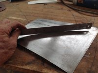
IMG_1734.jpg
Once the flange was rolled out over a stake with a plastic mallet, we can see the reverse curve the panel has taken. Without creating the pre-curvature, this would be more extreme. To reverse this effect, the large flange needs to be stretched, bringing the correct curvature back into the panel. The line above the ruler is where the reverse flange will be bent.
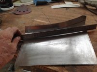
IMG_1735.jpgIMG_1737.jpg
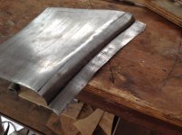
I used the bead roller to start the bend of the flange. This could just as easily been done on a sharp stake with a mallet but the bead roller was there so I used it. As the flange is rolled over, the outer edge is being forced to a smaller radius and therefore has an excess of metal, indicated by the ripples / waves in the flange. Other side effects are the straightening out of the curve of the fender shape and tightening the radius of the rollout from the flat section.
IMG_1738.jpgIMG_1739.jpg
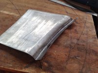
Shrinking the flange has the following effects
flattens the flange
allows the flange to be bent around further
reinstates the fender curvature
opens out the radius of the rollout and
reinstates the nice curvature of the main section.
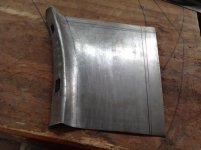
IMG_1740.jpgIMG_1741.jpgIMG_1742.jpg
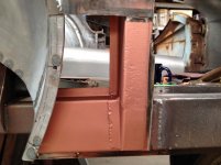
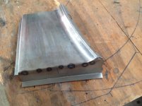
Time bend the reverse flange where the panel attaches at the front of the B post. This was done on a sharp stake in the vice with a plastic mallet. This had to be done on a stake because the sheet is curved in this area and a staight brake to bend the flange would have destroyed the panel curvature. The box section underneath was then added.
IMG_1743.jpg
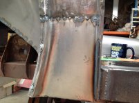
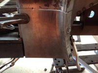
Clamped and finally welded in place. Spot welded to the inner sill underneath.
IMG_1744.jpgIMG_1751.jpg
Welded the inner panel in place.
IMG_1752.jpg
Got to spot the outer sills in place and that is the end of the body tub work!
 
Hi Lionel, once again great work and excellent explanation. I have not had much time to work on my frame this last week or so. Minor things to tidy up, coat the inside and I can get back to working on the tub. Probably going to finish up the front first, not much left to do to the front and that way I will see some progress. Then to the back where you post will be a lot of help and inspiration. Frank
 
Back
Top