• Hi Guest!
    You can help ensure that British Car Forum (BCF) continues to provide a great place to engage in the British car hobby! If you find BCF a beneficial community, please consider supporting our efforts with a subscription.

    There are some perks with a member upgrade!
    **Upgrade Now**
    (PS: Subscribers don't see this gawd-aweful banner
Tips
Tips

TR2/3/3A Rear tail light cutouts

5:30pm and still 42.5 degrees C. A very hot day in the shed. Not sure how hot in a leather apron and welding mask!

Slow week. A friend asked me to cut out the rust in his Toyota Landcruiser so that has been taking priority. I hate patch ups!

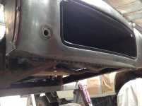
Finished the spare wheel carrier and fitted the front of the box section and mounting brackets. All parts are spot welded to the carrier base.
IMG_1595.jpgIMG_1596.jpg
This allowed the test fitting of the rear apron to refine the rear edges of the carrier base and also the final shaping of the curve along the bottom of the box section that links the apron to the front wall of the box section. This was spot welded to the flange at the bottom of the apron.
IMG_1597.jpgIMG_1598.jpg
The rear apron is temporarily bolted to the brackets / side panels with bolts through the rear mudguard mounting holes. It still has to be welded to the side panels and then seam welded around the edge of the wheel carrier and apron flange. Further, the flange on the base of the box section will be spot welded to the front wall of the box section.
IMG_1599.jpgIMG_1600.jpg

IMG_1601.jpgIMG_1602.jpg
Felt pretty good walking the length of the shed with the rear section of the car on the top of my head to test fit it on the chassis. (Small things amuse small minds!)
 
It amazes me how you are able to get those rear inverted /curve/angles around the back lights and spare tire. Your hand eye stuff is excellent because just filling that area with putty and working it into shape is a challenge for me.
 
Lionel, The back section is looking great! You are not fooling me, you have to have a really good mind to take a project to the level you have. I am having to do as you suggested and look and see what order to do the repairs to the back of my car. I am focusing on the chassis now and working on forming panels as I feel I have a picture in my mind of how to form the metal. My background is more to the industrial side ,rolling tubing, forming brackets, pans, tubing frames. Seeing the panels in 3D is not easy for me but it will come with time. Following your progress closely as it will help me down the road. Are you using any weld thru primer between the flanges you are spot welding? I have tried to use it a couple of times and tig welding does not like the primer. I decided the weld quality is more important and will rely on seam sealer, quality primer and paint to protect as much as I can. Keep up the great work.

Frank
 
David, the shine on the metal is from all the mis-hits!

The order of assembly is interesting and I think about how they assembled the car on the production line. I would love to be able to go and watch as they were assembled. The rear closing panel I got from KAS matches the picture on the Moss site in that the top flange points forward. My car original part as best I can make out was the reverse and this fits with my thoughts on access for the spot welder person. My order of assembly would be:

Start with front of box section for rear apron
closing panel spot welded on
mounting bracket welded to both above
attach all to spare wheel tub
rear floor panel to spare wheel tub
base of box section to rear apron
rear apron to all the above by spot welding the base of the box section to the front of the box section and then seam welding around the flange of the apron to the spare wheel carrier and the rear edge of the rear boot foor.

Doing it this way gives the spot welder clear access to all joints.

Frank I have been using some Upol #2 copper rich weld thru primer but tend to mask off the flanges where I spot weld. Zinc primers are definitely no go. The slightest hint causes an explosion and stuffs up the elctrode. I usually have a number of electrodes sharpened ready to swap out any contaminated ones. Even with panels that I have put rust converter on, I use emery paper to bring welding surfaces back to bright and shiny before welding. Like you, I will be depending on flooding sections with rust inhibitor once assembled and seam sealer.

Sounds like I will be calling on you when it is time for a roll bar. Freight from the states could be a killer though!
 
Hello Lionel

Here are some photos of the rear passenger quarter on my car. The new panel on the left was used but the one on the right had the captive nuts in the wrong place It should have had a 90 degree flange to spot weld it to the rear apron. I think the "U" cut shaped cut was part of damage repair.
I passed the panel on to someone who had a car that used that type.

David

Pannels purchased.jpg
Damaged area.jpg
 
My car is the early model the same as Lionels and that closing panel is the same as the one in Davids photo. This side on my car was quite rotten so I ordered a replacement from Kilmartin but it was the wrong shape so I unstitched it and welded some patches in and put it back on came out ok in the end

Graham
P1010018.jpg
 
Got back to it this week. Did some geometric gymnastics and worked out the position of the hole through the rear apron for the support bolts for the rear over riders. Didn't have the necessary 5/8th ID tube so rolled some from flat sheet and seam welded them along their length to create the necessary tubes. Had a practice run because the first two were not long enough.
Used a long centre punch to sight through from the mounting hole in the chassis to mark the exit point through the rear apron. Drilled the holes and then sized them with a rat-tailed file while sighting through to the chassis to get them aligned. Fed the tube through and cut to length allowing a couple of mm over length. Used this extra metal to fuse back to the face of the rear apron with the tig. Cuts down the amount of filler rod used. Dresed the face back with a flapper disk and then hand finished with a file.
IMG_1603.jpg
Filpped the whole assembly over and welded the tube on the other side where it comes through the box section, finally locking it together.
Finally ready then to edge weld the base of the spare wheel carrier and the rear edge of the boot floor to the flange in the rear apron.
IMG_1604.jpg
Had a minor stuuff up here. Realised when it was upside down, that I had not aligned the boot floor correctly with the apron so the edges did not align correctly across the width of the spare wheel carrier opening. Consequently, the weld is not fully an edge weld across the width. Too late to change due to the number of spot welds holding it all together. In the scheme of things, not a massive issue.
Ready now to look at reattaching the tonneau, inner wheel arches etc.
 

Attachments

  • IMG_1605.jpg
    IMG_1605.jpg
    54.2 KB · Views: 81
That hits the spot Lionel, have you looked at the small captive nuts for the leather straps in the spare tire well?

Graham
 
Graham, last minute job when I realised they were there as I was about to weld the whole assembly together. I put all the captive nuts on the spare wheel carrier and then realised I think they are the smaller diameter. Too bad, my TR will have heavy duty spare wheel tie downs in case I want to do off road work. Will just make the small clips to suit the bolts and paint them with "look small" paint.

Test fitted an over rider today. Had to turn up the spacer pipes and then made two 3/8th bolts to hold it all together. When I fitted the over rider, it stuck out at a terrible angle. Will have to finesse the shape of the mounting bar tomorrow to get it to align with the rear apron correctly.

All good fun!
 
Lionel have you noticed the small cutaway where the override bracket fits under the valence the cutaway looks like it gives clearance for the bracket.

Graham
IMG_1582.jpg
 
Funny you should mention that Graham. I found the bracket does touch the bottom of the valence and intended asking the question whether there should be a cut out. You beat me to it!
In actuality, I would have put a cut out in, regardless because I could see the bracket could not be bent in such a way as to nicely clear the valence.
Well spotted!
 
Last edited:
Not sure what is happening with my last post.

I do not see any photos that I uploaded but see instead "Attachment 57350" etc.
could someone let me know if they see the photos?

If I go to edit the post, I can see the photos!
lionel
 
No cant see the photos if I click on the attachment number it tells me I've done something wrong and to contact the admin.

Graham
 
Back
Top