• The Roadster Factory Recovery Fund - Friends, as you may have heard, The Roadster Factory, a respected British Car Parts business in PA, suffered a total loss in a fire on Christmas Day. Read about it, discuss or ask questions >> HERE. The Triumph Register of America is sponsoring a fund raiser to help TRF get back on their feet. If you can help, vist >> their GoFundMe page.
  • Hey there Guest!
    If you enjoy BCF and find our forum a useful resource, if you appreciate not having ads pop up all over the place and you want to ensure we can stay online - Please consider supporting with an "optional" low-cost annual subscription.
    **Upgrade Now**
    (PS: Subscribers don't see this UGLY banner)
Tips
Tips

TR2/3/3A Alternator Wiring for TR3

mgedit

Jedi Knight
Country flag
Offline
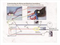
I have got my alternator installed (Denso 12185N) and am now turning to the wiring. I've reviewed various online threads and just want to confirm my wiring before starting to make connections. I had a non-working control box so I've taken the guts out of it to allow me to use it as a connection box.

Questions are part of the pictures as well.

1. D and F are connected inside control box via heavy resistor. I think I also need to remove this to separate F and D terminals. Is that correct?


2. Does thin yellow that was on D now move to F to connect to yellow/green from alternator? So wire from alternator is then wired directly to indicator light.


3. Is a fuse or circuit breaker needed on the output from the alternator (maybe inside control box between D and A1 and A)? If so, what size?


4. What gauge of wire should I use for inside box connections between D, A1, and A?


5. What gauge of wire from alternator (60 Amp) to D terminal on control box? Run about 3 feet, current wire from generator about .064 inch (so I think it is 14 gauge on the new harness I installed earlier)?

6. My plan to add additional circuits is to daisy-chain heavy white from old to new fuse box, move white coil wire over to second fuse box, take fan from new fuse box, take third wire from alternator (supposed to go to switched power) to fuse input (currently not used on second fuse box). Is this a reasonable approach, or is there a better way?

As usual, thanks so much for the help.

Cheers, Mike

Alternator_12185N.jpg

Control Box.jpg

Control Box and Fuses_1.jpg

Control Box and Fuses_2.jpg
 

TR3driver

Great Pumpkin - R.I.P
Offline
1. Yes.
2. Yes.
3. I wouldn't. The wiring is already sized to handle the maximum output from the alternator. If you want to add circuit protection, I'd suggest a fusible link at the point where the brown wire meets the starter solenoid. 14 AWG should be about right.
4. 10 AWG will do, 8 would be better.
5. Same as 4.
6. I would recommend not adding any heavy loads to the existing ignition switch (which is what supplies power to the white circuit). It's adequate for the stock loads, but easy to overload if you add more to it. Better to pull power either directly from the alternator output, or from the existing brown/blue or brown/white circuits. If the loads have to be controlled by the ignition switch, use relays.

Wiring the radiator fan directly into the ignition circuit also causes a strange symptom where the engine will keep running for several seconds after key-off, if the fan happened to be running at the time. The fan motor acts like a generator immediately after power is cut, and feeds power back into the coil.
 
OP
mgedit

mgedit

Jedi Knight
Country flag
Offline
Thanks Randall. Greatly appreciate your help. Will get started on this and check back if I have more questions. Cheers, Mike
 

M_Pied_Lourd

Darth Vader
Country flag
Offline
Mike, if you are interested, I can dig out the wiring documentation that came with mine.

Cheers
Tush
 
OP
mgedit

mgedit

Jedi Knight
Country flag
Offline
That would be great Tush. Always good to have additional documentation. Cheers, Mike
 

M_Pied_Lourd

Darth Vader
Country flag
Offline
Ok. I'll dig it out.

Cheers
Tush
 
OP
mgedit

mgedit

Jedi Knight
Country flag
Offline
OK, making some more progress. Sorry if I seem "slow" on this, but don't want to create electrical issues down the road. Mechanical things seem sort of obvious, electrical things not so much!

Based on Randall's input I've re-thought what I planned to do (see below) and purchased much heavier wire for alternator output.

Couple of additional questions.

1. The instructions with the electric fan suggest that the power be supplied from a switched source. When the car is shut off the alternator would no longer produce power so with a connection via the A terminal of modified control box would this serve the same electrical function? That is, is this the "equivalent" of a switched supply, or would the power still makes its way to the fan somehow? The fan will be wired via a relay provided with the fan kit. OK to do like this, or is there a better way?

2. The alternator has three outputs from the plug. The S goes to the output on the alternator, the L goes to the dash light, and the IG is supposed to go to a switched power source. The guy I bought the alternator from added a diode in the wire from the IG terminal and he suggested attaching wire to coil. I would prefer it attach at the firewall with the other control box/fuse box wires. I was going to attach at the white wire input to original fuse box, but Randall cautioned about adding extra loads to this circuit. Does this alternator connection add a significant load? Assume it makes no difference to load on ignition switch if I attach at either suggested spot. If load is significant, should the connection from white circuit to alternator be wired via a relay? If so, how would I do that?

For those who are interested, I found these wire gauge sites. No doubt lots of other sites too:

https://www.tessco.com/yts/industry/products/itm/automotive/get_wired.html

https://www.offroaders.com/tech/12-volt-wire-gauge-amps.htm

and a handy calculator:

https://www.gtsparkplugs.com/WireSizeCalc.html

Thanks once again for the help. Peace and Happiness to all at Christmas.

Cheers, Mike

Second Fuse Box2.jpg
 

TR3driver

Great Pumpkin - R.I.P
Offline
1. The instructions with the electric fan suggest that the power be supplied from a switched source. When the car is shut off the alternator would no longer produce power so with a connection via the A terminal of modified control box would this serve the same electrical function? That is, is this the "equivalent" of a switched supply, or would the power still makes its way to the fan somehow? The fan will be wired via a relay provided with the fan kit. OK to do like this, or is there a better way?
The 'A' terminal is a constant source, not switched. However, it is a good place to get power for the fan, as controlled by the relay. (IOW, one of the relay contacts gets wired to the 'A' terminal.) By having the power to the relay coil come from a switched source, the power to the fan becomes switched.
I'm not sure if I've explained that clearly, so feel free to ask again if not. Here's a sample diagram (from the Internet, not mine).
elec_fan_2.jpg

2. The alternator has three outputs from the plug. The S goes to the output on the alternator, the L goes to the dash light, and the IG is supposed to go to a switched power source. The guy I bought the alternator from added a diode in the wire from the IG terminal and he suggested attaching wire to coil. I would prefer it attach at the firewall with the other control box/fuse box wires. I was going to attach at the white wire input to original fuse box, but Randall cautioned about adding extra loads to this circuit. Does this alternator connection add a significant load? Assume it makes no difference to load on ignition switch if I attach at either suggested spot. If load is significant, should the connection from white circuit to alternator be wired via a relay? If so, how would I do that?
The IG terminal draws relatively little power. It should be fine to add that to either the white circuit or the green circuit. Using the fused 'green' circuit ensures that the ignition doesn't get shorted out if the regulator inside the alternator fails (but they very rarely do). Or if you want, tap the white circuit through a new fuse so that a failure elsewhere (blowing the original fuse) does not disable the alternator.
 
OP
mgedit

mgedit

Jedi Knight
Country flag
Offline
Thanks once again Randall ... very much appreciated.

Here is the diagram that came with the fan kit.

Fan_Wiring3 (Medium).jpg

So, am I correct is thinking that a good Power Source as per this diagram could be from my modified A terminal (via a fuse)? This is direct from the alternator via the modified control box. What size "British" fuse would be required? I have a spare blue 35A (same as used for the green circuit) that I got from TRF, would that be OK?

If I wanted to add an "override" switch to this setup (not sure if I really need or want to) how would I do that? From the diagram you included with your last reply it would look like a wire from thin blue that goes to the EFC via a switch to ground might do it? Somehow that does not seem to be enough. Is grounding that thin blue wire all that is needed? I've added a diagram of the relay terminal setup to the picture.

Cheers, Mike
 

Attachments

  • Fan_Wiring2 (Medium).jpg
    Fan_Wiring2 (Medium).jpg
    54.2 KB · Views: 98

TR3driver

Great Pumpkin - R.I.P
Offline
To work from that diagram, you need to leave out (or cut) the jumper between terminals 30 and 86 on the relay; and add another wire from 86 to a switched power source (eg white circuit). Then yes, your modified A terminal would be a good source for pin 30.
That way, the fan can only run if the ignition switch is on, but the ignition switch doesn't carry the current for the fan motor.

Grounding the thin blue wire is all that is needed to make the fan run whenever the ignition is on. The relay coil gets power whenever the key is on, through pin 86; so the controller grounds pin 85 to energize the relay and pass current to the fan through the relay contacts. If your override switch grounds pin 85, then the controller becomes irrelevant and the relay is energized whenever the key is on.

I put an override switch on mine, mostly because I didn't necessarily trust my home-made controller. So far, the only time I've really needed it was when I accidentally knocked a wire loose under the dash, and needed to get to an appointment before fixing the loose wire. But it has come in handy once or twice, when I wanted the fan to help cool the engine below normal operating temperature so I could work on it quicker. (Of course it's not as effective once the thermostat closes, but the extra air flow past the engine block still helps.)

Fuse size may depend on which fan you have. My Hayden only draws about 8 amps when running, but some of the high performance Kenlowe fans draw 20 amps or more. Your 35 amp British fuse would be fine for the Hayden, but not the Kenlowe. The fan motor draws a lot of extra current when first starting, so the fuse has to be oversized to avoid nuisance blows. Plus the "British" rating is actually twice the continuous current rating of the fuse. (Meaning that "35 amp" fuse is really a "17.5 amp continuous" fuse.)
 
Last edited:
OP
mgedit

mgedit

Jedi Knight
Country flag
Offline
Thanks Randall. Presume you mean terminals 30 and 86 in first couple of lines. So the idea would be to cut that red wire between 30 and 86 and run the cut end from 86 to the white circuit, and just insulate the end going to 30. Can you tell me why it would not work just feeding power from the A terminal to the 30 and leaving the wiring as is? That load is not going to the white circuit is it? Will try to find out what the draw of the fan is supposed to be. Thanks for your patience and valuable help. Cheers, Mike
 

TR3driver

Great Pumpkin - R.I.P
Offline
Thanks Randall. Presume you mean terminals 30 and 86 in first couple of lines. So the idea would be to cut that red wire between 30 and 86 and run the cut end from 86 to the white circuit, and just insulate the end going to 30. Can you tell me why it would not work just feeding power from the A terminal to the 30 and leaving the wiring as is? That load is not going to the white circuit is it? Will try to find out what the draw of the fan is supposed to be. Thanks for your patience and valuable help. Cheers, Mike
Oops, sorry about the numbers. I fixed the post, just to hopefully reduce future confusion.

Leaving them both connected to the A terminal would mean that the fan could run any time, even with the ignition off. Depending on your controller module (EFC), it will probably also be drawing power from the battery all the time, which could lead to a dead battery after long storage. (A simple thermal switch wouldn't do that, but the extra power to the EFC suggests that it has electronics of some sort inside, which get their power from the red wire.)
 
OP
mgedit

mgedit

Jedi Knight
Country flag
Offline
Thanks again Randall. Just looked up fan specs and it looks like draw is 8-9 amps, so I'm thinking the 35A British-rated fuse would be OK. Cheers, Mike

Fan Draw.jpg
 
Last edited:
OP
mgedit

mgedit

Jedi Knight
Country flag
Offline
Hopefully, my final question about this hookup. The location of that thin red wire is not very convenient as it is far from the fuse box and I'd rather not cut the kit wiring unless essential. I was thinking it might be easier to add a relay to feed the 12 V supply. If I'm finally starting to understand how this works, I would take the A terminal output from modified control box to the 35A fuse in my new fuse box, and from there run to the 30 terminal of a new relay. New wire from the white circuit would go to terminal 86 to switch the relay, a ground from 85, and the wire from 87 would provide a switched 12 V supply as per the original wiring diagram that came with the fan kit. Cheers, Mike

relay_pins.jpg
 

TR3driver

Great Pumpkin - R.I.P
Offline
Sounds good.
 

DornTRoriginal

Jedi Hopeful
Gold
Country flag
Offline
This Thread was great to follow along, I will be doing the same thing soon and I have copied the entire conversation to reference. Mike I agree electrical is sometime mysterious and confusing.

Here is where I am: I bought a new cloth wiring harness from TRF 15 years ago... then I bought an alternator conversion kit from Moss in 2013 and a new fan and fan motor from Wizard, refurbished all of the gauges 2014, thinking about LED lights etc. 2016 there's still lots to do... I've installed the alternator and fan prior to completing all the body work which is now semi 95% complete and I am on the path to putting my LBC back together with the usual struggles that you have all helped me through, thank you!
What would your advise be to regarding wiring everything when I get there; should I stick with the wiring harness I have and add new connections as Mike has done? I remember Pat G telling me he used a different wiring system and I saw his wiring system that was cool but I do not remember the specifics. I also recall a post where the entire wire harness was laid outside of the car and all of the wires were marked and tagged prior to running through the car which makes a lot of sense to me in order to have a good plan of what will be needed to do once inside the car. Is using the old regulator necessary or important other than for the same old look? I have installed heated seat pads and will also look to putting in a sound system. Over all I am trying to look original but I am not trying to be 100% stock as you can tell.

Thanks!
 

TR3driver

Great Pumpkin - R.I.P
Offline
Whether to keep the old harness or not is kind of a personal decision. I'm somewhat perverse (and cheap/lazy), I enjoy keeping as much original as possible (as opposed to reproductions of the original). So I've always added onto the original harness and that has worked out fine for me. I also make a lot of changes over time, since my original goal was to get the car on the road as quickly as possible. For example, the two new sub-harnesses in this photo were added at different times. (One of them to replace the original hydraulic brake light switch with a mechanical switch; the other to make the corner turn signals double as brake lights.)


But there is certainly a lot to be said for making a custom harness to match the car you are building, especially if you are replacing the harness anyway. FWIW I've heard that British Wiring will build a harness to your specifications, using period-correct wire and jacket (if you want).

No need to keep the original control box, if you don't want to. It's not needed with an alternator, especially if you are using a custom harness. With the stock harness, it makes a convenient way to tie wires together that need to be tied together but a custom harness would just have continuous wires and no connections to make there.
 
OP
mgedit

mgedit

Jedi Knight
Country flag
Offline
Glad that this thread will help someone else. Great thing about the forum is the people like Randall who are always willing to share their knowledge and help educate those of us who need some coaching. Cheers, Mike
 
Similar threads
Thread starter Title Forum Replies Date
K TR2/3/3A British Wiring alternator conversion kit question. Triumph 3
F TR2/3/3A I'm stuck... alternator/wiring/starting/? Triumph 2
apbos Positive Ground Alternator wiring. Spridgets 9
BoyRacer Wiring question for alternator conversion Austin Healey 3
G TR2/3/3A Wiring ammeter with the British Wiring alternator conversion. Triumph 13
D TR2/3/3A Alternator wiring diagram Triumph 7
M wiring of alternator Austin Healey 3
T TR2/3/3A Question on wiring Denso alternator through ammeter Triumph 4
K TR2/3/3A Triumph Rescue/British Wiring Alternator Kit Triumph 10
N Spitfire alternator wiring question Triumph 1
K TR2/3/3A Alternator from British Wiring Triumph 12
Lukens TR2/3/3A Help wiring convertion alternator Triumph 6
B TR6 Does a 75 amp alternator require a wiring upgrade of any kind? Triumph 3
bash Alternator wiring question Triumph 5
D MGB mgb 77 alternator wiring. MG 2
Patrick67BJ8 Alternator Conversion & Regulator Wiring Help Need Austin Healey 11
H TR4/4A tr4 alternator wiring Triumph 4
I Alternator wiring Austin Healey 5
E BE Alternator Wiring Question Spridgets 5
T TR4/4A TR4A alternator conversion wiring question Triumph 28
tweety Alternator wiring connector, Sources? Spridgets 4
G MGB Alternator wiring "71 MGB MG 4
bill_powell Alternator Conversion / Wiring Spridgets 13
kodanja Alternator upgrade wiring? Triumph 30
kyreb1862 MGB 77 MGB Alternator Wiring MG 4
B TR6 71 TR6 Alternator Wiring Triumph 2
Webb Quick Alternator Wiring Question Triumph 3
Airfix TR6 TR6 alternator wiring? Triumph 5
D Alternator Wiring MG 7
C Wiring Check. Alternator wiring. MG 19
LastDeadLast Bosch Alternator Wiring Question Triumph 1
I MGB Alternator help MG 0
P Alternator Installation Pic Austin Healey 4
P Generator to Alternator Swap Austin Healey 2
W Generator or Alternator? Austin Healey 18
Writer2022 GT6 GT6 MK3 Alternator Problem Triumph 4
K TR2/3/3A Is it time for a new alternator??? Triumph 8
M Smog pump and alternator brackets Spridgets 0
V MGB Never occurred to me that my '66 would be positive ground. Does the presence of an alternator show that it's been converted? MG 22
A General MG 78 MG MIDGET ALTERNATOR SMOKES MG 5
E MGB external alternator regulator MG 2
DrEntropy MGB Generator to alternator swap MG 1
M TR2/3/3A Generator Warning Light on with the Alternator Charging the Battery Triumph 4
K TR2/3/3A Overtightening the alternator belt? Triumph 14
B TR6 Swapped Lucas to GM alternator Triumph 9
M TR6 Alternator Issue for 72 TR6 Triumph 7
K TR2/3/3A Can anyone confirm that if you replace the ammeter with a voltmeter ( generator removed and alternator added) that you...... Triumph 5
K TR2/3/3A Red ignition light stays on...car has alternator not generator. Triumph 17
K TR2/3/3A TR3 with alternator conversion... red light stays on and low voltage on the voltmeter gauge? Triumph 1
G Spitfire Alternator troubles Triumph 2

Similar threads

Top