• Hi Guest!
    You can help ensure that British Car Forum (BCF) continues to provide a great place to engage in the British car hobby! If you find BCF a beneficial community, please consider supporting our efforts with a subscription.

    There are some perks with a member upgrade!
    **Upgrade Now**
    (PS: Subscribers don't see this gawd-aweful banner
Tips
Tips

Wiring question for alternator conversion

BoyRacer

Jedi Warrior
Country flag
Offline
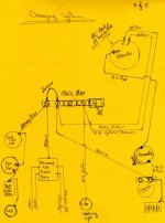
I'm hooking up a one wire alternator and I'm eliminating the control box from the firewall. It seems to me that I need to tie the 3 brown wires together. I think I can delete the field wire (yellow and green) altogether. I am a bit confused about what to do with the 2 yellow wires that connect to terminal "D". I am not going to use any warning light.
 
I have a 3-wire, but think at a minimum you can do this:
Leave the small yellow and yellow/green disconnected. Use the large yellow as your alternator wire, connected to the 3 browns at the firewall.
One friend has done this and has inserted a 25 amp fuse between the large yellow and 3 browns.

Personally, I didn't think the large yellow was beefy enough and ran a 10 ga red wire from the alt to the starter solenoid hot post. But the friend hasn't had problems with his setup.
 
Here is the drawing that I drew after I did my BJ7. A couple corrections you should notice. 1. is that where I labeled a wire at the alternator as yellow brown is actually yellow/green. 2. Also just ignore the the insertion of the amp meter. But do use the #10 red wire from the alternator to the solenoid ( this is your most direct path for charging current back to your battery).
The two wires that were connected to the "D" terminal of the voltage regulator are the wires for the warning light. ( should be yellow ). As I look at my drawing I realize that I reversed the labeling on the yellow and yellow/brown wire from the alternator. But you can eliminate yellow and the yellow/green wires on your regulator terminals of "D" & "F" since you are using a one wire alternator.
But make sure you do not have any hot wires hanging under your dash because the other wire at the old warning light location is coming from your ignition switch and should be white. Sorry for the confusion in colours but the drawing works. The terminal switch is in place of the voltage reg.
 

Attachments

  • img182.jpg
    img182.jpg
    25.1 KB · Views: 148
Just some comments about the use of one wire alternators verses the 3 wire set up. From my studying this over the years I have read some people with 1 wire alternators, this includes this use on many makes of cars besides Healeys, have reported an inability to keep their batteries well charged. I believe the reason for this is the nature of the way the 1 wire alternator senses the voltage in the system. It's sensing ability is off of the field terminal of the alternator. In a 1 wire alternator there is an internal jumper between the battery terminal and the field winding. Which means the alternator senses its own voltage which is always good if the alternator is working correctly. Because it always sees good voltage it doesn't always charge strongly enough to recharge the battery fully. In the 3 wire alternator the field terminal is connected over in the wiring harness closer to the load. Either at a voltage regulator terminal or at some point common to the power parts of the circuit such as a terminal in my drawing. Since it is connected where is will sense the effects of load currents it also senses differentials in voltage drops hence it sees lower voltage which then tells the alternator to charge more. So the 3 wire system has a better ability to keep the battery fully charged.
Just my take on the two different systems. Dave.
 
Back
Top