• Hey there Guest!
    If you enjoy BCF and find our forum a useful resource, if you appreciate not having ads pop up all over the place and you want to ensure we can stay online - Please consider supporting with an "optional" low-cost annual subscription.
    **Upgrade Now**
    (PS: Subscribers don't see this UGLY banner)
Tips
Tips

TR2/3/3A more timing related questions

TexasKnucklehead

Jedi Knight
Country flag
Offline
TR3 timing: Ping versus Instrumental

Numerous times I have heard someone ask for the proper method to set engine timing on a TR3. Generally, the most accepted answer is to set it statically at 4 degrees BTDC, then warm it up and advance the timing until it “pings” and then back off a few degrees. I found this method confusing and was unable to satisfy my idea of “properly timed”. Either I am not hearing the ping, or I am not doing it properly. After trying that approach, my engine either performed terribly or ran so hot it could melt the bushing out of the generator. I was reminded of the difference between a “gauge” and an “instrument”. I wanted to use an instrument and know it was timed accurately.

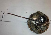
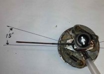
All my distributors are of the original DM2 type. If I remove the breaker plate, the points rotor and advance spring weights, I can see 15 degrees stamped on the lower plate. That is the maximum advance possible from the mechanical advance given in distributor degrees (same as cam degrees since it is driven from the cam but ½ of crankshaft degrees since the crank rotates twice per cam rotation). I was unsure if this marking was crankshaft degrees, or distributor degrees, or if it had been modified, so I made a “gauge”. I used a protractor, marked a sheet of paper with 15 degrees, punched a hole in the center, and slid the shaft with weights into the center. The deflection allowed by the weights moving without the shaft moving is 15 degrees. The Lucas DM2 spec shows full advance occurs by 2700 RPM (cam?). The Tachometer shows engine (crankshaft) RPM (Revolutions Per Minute) –even though it is actually driven from the distributor.

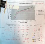
I picked up a fancy timing light from a discount tool store. It included a numbered knob to allow one to ‘dial in’ timing advance. That tool proved to be a gauge, not an instrument. (The ‘dialing in’ caused inconsistent, erroneous, unusual and unbelievable behavior.) Anyone using a timing light attempts to set the timing at idle. If you cross reference the Lucas advance chart, you can see that being off as little as 100 RPM will cause a few degrees of timing error. Couple that with the fact that at low RPMs, a change in RPM will affect the mechanical advance (timing), as well as any change in the timing will affect the engine RPM. This can be a frustrating adjustment.

Still, I wanted to know what advance I was running at engine idle speed. The dash mounted tachometer is a gauge (not an instrument). At idle, the needle is bouncing so that I can’t tell the engine speed within a few hundred RPMs –let alone the possible accuracy of the measurement. I attached my O-scope (a calibrated instrument) to the minus side of the coil, and accurately measured the time between 2 sparks at 39mS (.039 seconds). The time between sparks is ¼ of a complete cam rotation. There are 60 seconds in a minute. Time per rotation needs inverted (1/x) to be the same unit as the tachometer, revolutions per time. The result needs multiplied by 2, since cam rotation is twice crank rotation. So, 39mS X4 /60 INV x2 = 769RPM. Simplified, RPM=30/t. With this formula and instrument, I could accurately set the timing at idle. Each time I look at that formula, I hear Bob Dylan “and revolution in the air”.

I hope much more time is spent with the engine running above the curve of the advance, and think this is the place to concentrate. Knowing full advance occurs at 2,700 RPM. And knowing the 5.5” crank pulley has a hole at TDC, I calculated 30 (2 x 15 max distributor) degrees to be 1.44”. I cut a slit on a piece of paper 1.44” from the edge and used this “gauge” to paint a red mark on the crank pulley to indicate full advance. The timing light at any RPM over 1350 shows the pointer mark at max advance. If not, it takes a simple rotation of the distributor to get the TR3 perfectly timed. Allowing the engine to rev down to idle shows the pointer somewhere between TDC and MAX advance. I can quantify idle speed, and advance, but it doesn’t matter since I do not intend to change the advance curve characteristics.

My “gauge” is how it runs. It accelerates very well, and is no longer running hot (I will leave the discussion of the temperature “gauge” for another time).

My questions are, if I was supposed to set the static timing at 4 degrees, should my max be 30, or 34 degrees? My Haynes manual, under ignition system, says max advance in crank shaft degrees is 15. How can that be? My distributor vacuum unit does not leak, but I can’t find a way to see it change advance. The same manual indicates max vacuum advance of 8 degrees. How/where should I see that? I have a pair of H6S (short) installed which has a single vacuum port in the top of the forward carb, and in front of the throttle plate (air filter side). I can’t feel it sucking, but that’s where I have the advance line connected. A few months ago, I drove home from Baton Rouge and calculated better than 30 miles per gallon.

The more I understand, the more I know I don't understand.
 

Attachments

  • dist_wts_closed.jpg
    dist_wts_closed.jpg
    121.1 KB · Views: 108
  • dist_wts_open.jpg
    dist_wts_open.jpg
    105.8 KB · Views: 117

CJD

Yoda
Country flag
Offline
You've been busy...

First, if you are seeing the timing bounce at idle, you are already in the mechanical advance curve at idle. This is verified since full mechanical timing is in by 1350 RPM. You would benefit from stronger advance springs. The problem with being "in the advance curve" at idle is that you will have an inconsistent idle as the engine revs down to slightly different timing values each time you let off the gas.

The total mechanical advance would be 34 degrees. This is the 15 distributor degrees you measured at the weights (times 2 for 30 crank degrees) plus the 4 degrees you added by setting the distributor in an advanced position to begin with.

The vacuum port is not active till the throttle butterfly is opened a few degrees. The 8 degrees you are supposed to have is, again, distributor degrees. So vacuum advance at the crank would show as 16 degrees, and that would be added to whatever mechanical advance you have for a given rpm. To check the vacuum advance...you can hold the throttle open...which is kinda scary peering into a revving fan to check the timing marks...or just disconnect the advance line, use a tube on the advance unit and suck while using the light to see how much advance you increase.

So, to summarize...at idle you should show in the neighborhood of 4 degrees of steady advance. As you rev, the advance should kick in just above idle, and top at roughly 30 degrees total by 2750rpm. If you engage the vacuum advance at idle, you should see roughly 22 degrees at the crank, and while reving a whopping 52 degrees. I say roughly, because the drive test for "pinking" will likely result in a few degrees more or less.
 
OP
T

TexasKnucklehead

Jedi Knight
Country flag
Offline
Thanks, I am actually taking that correspondence course at home. It is enlightening, but not very specific. I forgot that section was in there, but it doesn't solve my problem.

The Bently shows more specific information under "Design Data". Referencing Distributor RPM, Distributor advance is from 2 to 14.5 degrees, at 200 to 2,000RPM. That is a crank/tach reading of 100RPM for 4 degrees at the crank pulley. The TR3 engine will not run itself at 100RPM.

I agree that throttle blips will settle back down to a different idle value depending on where the advance springs return. That is a function of the design, probably to allow easier hand cranking. But my idle is very steady (verifiable by the scope) while the gauge is bouncing. With a fraction of a turn on the idle screw, I can change the idle RPM by 1, and see the change on the scope as well as hear the tone change. I have the lowest steady idle when I warm the engine and shut it off. Then I slightly pull the choke and hit the starter button. As soon as it smooths out, I press back the choke and it will be at about 800 RPM. (The springs never get pulled when the rotation is slow.)


I need to investigate why I have no vacuum.
 

TR3driver

Great Pumpkin - R.I.P
Offline
All my distributors are of the original DM2 type.
So that is the first important question: What part number distributor do you have? There were at least 3 different models of DM2 distributors used on TR2-3A by the factory, with similar but not identical specifications. However, basically any DM2 will physically interchange and I can't tell you how many times the parts counter guy said "They're all the same" to me back in the 70s. One of my TR3 engines came to me wearing a distributor from an MG Midget! And of course without knowing what it is, you don't know what to expect from it.
The Lucas DM2 spec shows full advance occurs by 2700 RPM (cam?).
After some investigation, I believe that all of the Lucas distributor specifications are given in distributor (camshaft) rpm and degrees; even when the manual in question specifically says otherwise. It makes a moderate amount of sense for Lucas to always have given specs at the distributor shaft, since they did not make engines and the same distributors could have been used on 2-stroke engines where the distributor turns at crankshaft rpm. But it appears that the manual authors were not always aware of this, and sometimes assumed (and printed) otherwise.

I'll add that the Haynes manual in particular has many mistakes and omissions; I wouldn't trust it for anything without confirming against a factory publication. There are even different versions of the Haynes manual, with different mistakes.
Anyone using a timing light attempts to set the timing at idle.
Personally, I use mine to confirm (not adjust) the timing function throughout both rpm and vacuum ranges. Idle, as you've noticed, isn't all that interesting.
I attached my O-scope (a calibrated instrument)
I'm curious, since you brought it up, what is the accuracy specification for the horizontal timing base on your oscilloscope? Modern high performance digital scopes can be very good, but older analog scopes usually weren't so good. If it is only 1% (and your scope meets the specification), then your 769 rpm could actually be anywhere between 762 and 776.
The timing light at any RPM over 1350 shows the pointer mark at max advance.
That seems like a red flag, to me. Your distributor is clearly not behaving in the specified fashion. Either it is "broken" or someone has deliberately changed the advance curve (as I understand Advanced Distributors routinely does).

Checking max advance is a good idea, but since it shouldn't be reached until 5400 crankshaft rpm, it's not something I check very often on the engine. That hard stop isn't going anywhere.

My questions are, if I was supposed to set the static timing at 4 degrees, should my max be 30, or 34 degrees?
Maximum timing is initial advance (the 4 crank degrees), plus maximum centrifugal advance (30 crank degrees), plus maximum vacuum advance (as much as 20 crank degrees, depending on which vacuum module you have). So assuming you have the vacuum disconnected and initial (static) advance set to 4 degrees, you should see 34 degrees at 5400 rpm.
My Haynes manual, under ignition system, says max advance in crank shaft degrees is 15. How can that be?
I believe it is simply wrong. There are many mistakes in the specifications for the earlier cars. As another example, as I mentioned, there were three different distributors fitted between 1954 and 1960, yet there is only one set of numbers given. The 40698 fitted in 1960 specifies no advance below 450 (crank) rpm, while 40403 and 40480 both specify 2 (crank) degrees at 400 (crank) rpm.

My distributor vacuum unit does not leak, but I can’t find a way to see it change advance.
Normally, the vacuum advance is only active with the throttle partly open. It is deliberately disabled with the throttle closed. So the only way to test it is to either run the engine under a load (so you can open the throttle without overspeeding the engine), or apply an external vacuum source. A Mity-Vac (or the cheap HF equivalent) works well for this; but you may need to make up an adapter to mate to the fitting on the vacuum advance.
The same manual indicates max vacuum advance of 8 degrees. How/where should I see that?
Connect a MityVac, pump it up to the middle number in the vacuum unit specifications (which should be stamped on the barrel of the unit), check the change in timing.
A few months ago, I drove home from Baton Rouge and calculated better than 30 miles per gallon.
I'd say that is pretty good evidence that the vacuum advance is doing it's thing.
The more I understand, the more I know I don't understand.
This seems to be the way of the world. No matter what the topic, there is always more to learn and each stage of learning only demonstrates how much more there is out there. We haven't even begun to talk about what really constitutes "optimum" timing or how to get it. The factory timing curves were only a rather conservative approximation at best, and make lots of assumptions that may not be true today. For example, both volumetric efficiency and mixture affect the speed of the flame front within the cylinder, which in turn affects optimum timing. Your HS6 carbs won't be quite the same as the stock H6 ones, thus your engine may perform better with a different curve and initial advance. Fuel plays a big role too, and what we get at the pump today doesn't bear much resemblance to what it was in the 50s, even if you are lucky enough to have non-alcoholic fuel available to you.

Here's a write-up I came across, for a little further reading. It's looking at a forced-induction point of view, but the processes and relationships are the same. Things just happen faster with the cylinder pressure above ambient instead of below.
https://www.superhonda.com/forum/f5...ming-writeups-i-have-ever-come-across-268106/
 

TR3driver

Great Pumpkin - R.I.P
Offline
The Bently shows more specific information under "Design Data". Referencing Distributor RPM, Distributor advance is from 2 to 14.5 degrees, at 200 to 2,000RPM. That is a crank/tach reading of 100RPM for 4 degrees at the crank pulley.
No, crank rpm and degrees are twice distributor rpm & degrees. So that 200 rpm would be 400 rpm indicated at the tach. And, although a stock engine should be capable of running at 400 rpm, I believe those instructions are intended primarily for testing on a distributor test machine.

I can change the idle RPM by 1, and see the change on the scope as well as hear the tone change.
Wow, talk about perfect pitch! Are you a musician?
I press back the choke and it will be at about 800 RPM. (The springs never get pulled when the rotation is slow.)
Assuming you have the 40480 distributor, you should already have 2 (crank) degrees of advance by 400 (crank) rpm. If you aren't seeing anything by 800 rpm, you may have one of Jeff's specials. He specifies to no longer use the factory initial setting and instead recommends (I believe) something like 10-12 BTDC initial timing at 800 rpm.

I need to investigate why I have no vacuum.
Working "As designed". If you pull the carb apart, you can see that the throttle plate moves over the hole, so that at idle, the hole is on the intake side of the throttle plate and so "sees" only a very slight vacuum (the drop through the air filter and venturi).
 
OP
T

TexasKnucklehead

Jedi Knight
Country flag
Offline
Thanks, Randall.

I can always count on someone to show me where I've made a stupid mistake. All along, I have been thinking cam speed is 1/2 crank speed, but dividing cam speed (instead of multiplying) by 2 to get crank speed. That makes a world of difference and now I realize that the curve does not top out nearly as early as I expected -and why setting the timing has to be so complicated.

My scope is a relatively old (300Mhz) storage scope TEK2440 with time base accuracy of .0015%. I think its more than adequate to measure RPM accurately.
 
OP
T

TexasKnucklehead

Jedi Knight
Country flag
Offline
I picked up a "Brake bleeder kit" that worked perfect for checking out the vacuum advance. My Bently implies the unit should be different from the 2 units I have. Both the ones I own are stamped 4-11-7. I measured and marked the points breaker plate and case, so I could see the effects of vacuum at different levels. When I installed my Crane ignition, I built a complete "new" distributor so I could keep the whole points system as a spare. Now I know that one of the vacuum units does not function (it leaks so much that it can't). I moved the 'spare' (working) vacuum unit to the Crane system presently installed.

I measured the diameter of the breaker plate at 2.5", and calculated 7 degrees as .152", and the vacuum seems to advance it about that much. After reading the article Randall mentioned, I am just as clueless as to how I should modify the advance curve, or where the timing should be set, but I am pretty sure my primary spring is not returning 'home', and the vacuum unit presently installed is working. Springs are on order, I need some parts for the scope, but the TR3 keeps getting better -even if I feel like I'm beating a dead horse.

Thanks for the feedback, explanations and patience.
 

TR3driver

Great Pumpkin - R.I.P
Offline
My Bently implies the unit should be different from the 2 units I have. Both the ones I own are stamped 4-11-7.
There were several different distributors used during TR3/A/B production, but the Bentley lists only one (probably for TR2).

Your figures appear to be correct for a 40698 distributor, which my Lucas catalogs say was used on 1960 through early 1962 TR3. However, 40698 is listed in Practical Hints 5th edition, which I think would have only covered TS50000 to TS60000, so something isn't quite right. PH 6th edition lists 40795.
 
OP
T

TexasKnucklehead

Jedi Knight
Country flag
Offline
so something isn't quite right.

You could say that about much of my TR3. It was under 20' of Katrina after a previous restoration so any notion of 'right', at best, is a notion. My goal was to do as good as I could and end up with a drive able car that retained the original curb appeal, on a budget.

I have oversize pistons/liners and H6Ss, as well as a Crane ignition, TR4 camshaft, toyota 5-speed etc. Guessing what the right distributor might be, or was, is still a guess. The distributor I have the points installed is a 40480D V167 359 (which my Lucas pdf shows was superseded by 40698A) -though only the case of it could be used, so the shaft, plates, weights, etc are from another 40698A. The distributor with the Crane installed, is 40698A V202 560. The vacuum unit is from the flooded car and still works. The car was titled as a 1956, but the engine is TS50903E (the trans was TS50935) and has no right hand steering blanking plate hole. All the Lucas switches, steering box, steering cam, and generator, had date codes from the first half of 1959. But, I have a copy of a (slightly modified) British Heritage Certificate showing the actual, present configuration. The "toyota 5-speed option" is a dead give-away that "something is not quite right here".

We had an out of state visitor that requested a ride in my TR3. Sunday morning before the cold front came in, we were cruising with the top down on some local back roads. The sun was shining, the wind was in our hair and the TR3 seemed to perform well. We shared the opinion that "all was right in the world". (Though I hadn't yet identified the leaking vacuum advance module...)

Someday I may pursue 'right', but for now, I am very happy doing as good as I can. -and I would be wrong to think this forum did not have a huge part in it.
 

TR3driver

Great Pumpkin - R.I.P
Offline
Guessing what the right distributor might be, or was, is still a guess.
One approach, that I think might work well (but haven't tried), is to get some "laptop dyno" software that can detect and record acceleration vs speed (typically by listening to the exhaust note through a microphone). Find a stretch of flat, level road where you can make repeated speed runs. 2nd gear will do, so you don't need over 50 mph. Do at least two runs each direction, recording acceleration vs speed from around 2000 rpm up to 5000 rpm in 2nd gear. Then back off the initial timing by 2 or 3 degrees and try again. Then a third set, with the timing advanced 2 or 3 degrees from where it was to begin with. (Obviously, back off if you can hear knock or preignition; but power will drop before you can hear it anyway.)

Averaging and plotting the results should give you an indication of whether the engine wants more, or less, advance at each rpm. Make the indicated changes, then try again.

Or of course you could do all this on a chassis dyno. You'd get more accurate results in fewer runs (and less time between runs), but dyno time gets kind of expensive.
 
OP
T

TexasKnucklehead

Jedi Knight
Country flag
Offline
My idea of "re-curving the advance" has taken on new meaning. I will explain how I improved the timing of my TR3. I doubt it was ever off much, but anytime I added a variable, I also added more ambiguity of the overall system. I don't pretend to know what the right curve should be, but I am sure my advance was far from original, and is much better now. Finally, I am fairly sure the advance is working as designed and the car is running well. It seems to easily go through the gears, accelerates without labor, and is not overheating. Now I think "re-curving" means "restoring the original curve".

I found that vacuum is responsible for up to 16 degrees of crank advance. Also, I found quantifying the centrifugal advance is not possible without disconnecting the vacuum (with my H6Ss, by 1500 RPMs, there is noticeable vacuum advance added). The way I tested vacuum advance, was to use a vacuum brake-bleeder system on the vacuum module. With the car not running, you can see the points plate rotate (I scribed marks on the distributor case, and points plate). Distributor advance at 18"hg (indicated on tool vacuum scale) should be between 6 and 8 degrees (.175" and .130"). 9.5"hg should be between 7 and 5 degrees (.152" and .109"). 4.75"hg should be between 2.5 and .5 degrees (.055" and .01"). These are difficult to accurately measure, but the exercise proved one of my units failed miserably. I had assumed it was OK, when it would not advance at all.

Mechanical (centrifugal) advance took a little more effort. First, I referenced the TR3 Advance Curve from the manual. The attached picture shows how I calculated the distance from the TDC point for each crank RPM/advance. Then I made a "scale" on some tape, attached to a toothpick. I inserted the toothpick into the TDC hole, and marked corresponding different colored spots on the crank pulley for each of the advances. I attached an oscilloscope to the coil. My scope has "vertical measure bars" that can be set for the desired period between plug fires to accurately measure the crank RPMs. An inductive meter, coil meter and dash meter were not accurate or stable enough to measure the range of RPMs. A timing light easily shows the advance (marked with a different color) at each of the interesting points (I stopped at 4,000).

My original distributor was not performing as expected, neither was the 'new' one with a Crane ignition installed. Mechanical advance is controlled by 2 weights and 2 springs under the breaker plate. Of the 3 distributors I have, 1 had a pair of weights that weighed 45g, 1 had a pair of 46g, and 1 with a pair of 47g weights. The difference in weight in a given set was less than .2g. I used the heaviest ones for no particular reason. Generally the springs have 2 different strengths. The 'free lengths' (and strengths) are different to create the change in the slope of the curve (the curve is really 2 different slopes controlled by the combined effect of the weights pulled by the springs and the rotational force). The max mechanical advance is controlled by stopping the outward motion of the weights (a hole limits the movement of a peg under the weights). (Max advance occurs at red line, and was not checked.) I measured the length of the springs fully closed and open. All my old springs were longer than the minimum distance -problem number 1 (the advance cannot return to "0" without spring force). I made a 'gauge' from a piece of wood with 2 nails separated by the same distance as the max distance. I used a small digital spring scale to pull each of the springs to the max distance and charted them, as well as the new Moss dist springs. The new springs seemed to take more linear force and varied from max of 1.3Kg to 4.0Kg, while the old springs seemed to take full force to move at all -from 5Kg to 8Kg. The first new set of springs I tried were the shortest (15mm and 1.3Kg to max length) and 2nd from strongest (16.5mm and 3.0Kg to max length). Running, the TR achieved max advance too early, so I changed the 3.0Kg spring to 4.0Kg.

Now, with vacuum disconnected, at 800 Rpm idle, the timing light shows the indicator between the two yellow dots (4 and 16 degrees). I used the 1st yellow dot to set the static timing. At 1,000 RPM (30mS between spark fires) I am spot on the 2nd yellow dot (16 degrees). At 2,000 Rpm (15mS) the timing light is on the blue spot (though blue is a difficult color to see) (24 degrees). At 3,000 Rpm (10mS) the timing light shows the indicator on the green spot (26 degrees). Note these spots get closer together, and I did not want to rev the engine any higher without a load.

Connecting the vacuum, the timing 'jumps' when accelerated to any given point, and is a little more advanced than the spot would indicate. I have "re-curved" my distributor advance and am happy with it.
 

Attachments

  • RPMadvance.jpg
    RPMadvance.jpg
    185 KB · Views: 77

CJD

Yoda
Country flag
Offline
So the stronger springs fixed things. Good to hear. I know it's not as accurate, but I love my dial a time light when it comes to mapping the curve.

I initially had the same thought as you, that the double curve was determined by the combination of the weak and heavy spring. After really looking at the distributors (when I was rebuilding 5 at once a couple months ago), I no longer think that is the case. The two weights have different springs...but they are mechanichally linked so they have to rotate together. The both hit the advance stop together too, no matter how different the springs are. Because of that, I now think the double curve is mechanically built into the way the wieghts pivot using the little brass fulcrums. If you used two heavy springs, I think you would still get the double curve...
 
OP
T

TexasKnucklehead

Jedi Knight
Country flag
Offline
John,

I too was a little curious about the little brass fulcrums. If you look closely, and rotate the assembly in and out, you can see the fulcrums never switch over; that is, the spring is always attached to the inside of the slot. So the overall length does not change. I am confused as to the exact purpose, other than to allow the spring to move freely.

If you look at this attached document, it explains the difference between the primary (slow/short/weak) spring and secondary spring, and how different springs can affect the curve.

The bottom line for me was that the springs were not returning the advance to the starting point, and the vacuum module failed, and the 50 year old springs probably no longer acted like new.


-actually it appears the pdf is too large to be included. It is called "tuning the lucas distributor", I will email it to you if you remind me of your email address
 

TR3driver

Great Pumpkin - R.I.P
Offline
If you used two heavy springs, I think you would still get the double curve...
Only if the two heavy springs were different lengths. It's the length difference that splits the curve; the fast part is when only one spring is resisting the motion of the weights.
 

Geo Hahn

Yoda
Country flag
Offline
...I initially had the same thought as you, that the double curve was determined by the combination of the weak and heavy spring.... I no longer think that is the case. The two weights have different springs...but they are mechanichally linked so they have to rotate together. The both hit the advance stop together too, no matter how different the springs are. Because of that, I now think the double curve is mechanically built into the way the wieghts pivot using the little brass fulcrums. If you used two heavy springs, I think you would still get the double curve...

Just off the top of my head I have to disagree. It appears to me that the light spring allows both weights to swing out readily to a point where the heavy spring comes into play (I think it is actually loose when the distributor is at rest). The heavy spring then slows down the movement of the weights which is what puts the 'knee' in the curve.

I think you had it right and talked yourself out of it.
 

CJD

Yoda
Country flag
Offline
So, you guys are saying the heavy spring should be loose while the distributor is sitting still?
 

TR3driver

Great Pumpkin - R.I.P
Offline
Certainly one of them should be loose. From the charts I've seen, it is usually the heavier one.
 

CJD

Yoda
Country flag
Offline
I never would have thought! The loose springs all look stretched out of shape. I thought that was from use, but it would seem some guy with a distributor machine actually stretched it just enough out to control the second advance curve start point.
 
OP
T

TexasKnucklehead

Jedi Knight
Country flag
Offline
The stronger spring should be loose between the posts at rest -but I also think it depends on the springs. The new Moss assortment of springs all had a free length less than the fully closed position (but different strengths). If you hadn't read "tuning the lucas distributor", I'd suggest it. The knee (or change in slope) of the curve, is where the 2nd spring comes into contact. From that point forward, both the springs tensions are slowing the curve.

So, the first spring is weak and barely resists the outward movement of the weights, which causes the sharp advance slope. The 2nd spring finally comes into play when it's free length is taken up, and joins the 1st spring resisting the weights outward movement causing a slower ramp/slope/curve. It seems to take a lot more spring force at higher revolutions, so, even with 2 different free length springs and spring forces, with them both tight at rest, the curve can still happen. It is certainly easier to visualize when one is not in contact at rest.

I spoke with a friend this weekend who used to do a lot of work on Triumphs and Jaguars. He claims these cars were delivered from the factory with spots of white lithium grease under the weights. The weights must move in and out freely, but I hadn't thought of greasing them. Now, I have a nice smooth idle (always returning to the same RPM), and my car is running great.
 
Similar threads
Thread starter Title Forum Replies Date
Michael Oritt Replacing timing chain tensioner and more Austin Healey 24
T TR2/3/3A Is there a timing cover seal that will last more than a couple of year? Triumph 23
K TR2/3/3A More on setting the timing... Triumph 12
Bayless More Prefect Progress Other British Cars 2
B MGB while driving engine cuts out if I let off or push more throttle it comes right back on MG 5
C MGB More Weber help needed MG 27
DrEntropy More lessons in Japanese engineering Other Cars 7
KVH General Tech More Technical Questions—TR4 Triumph 5
KVH General Tech Heater and Vent Control Cables--TR2 thru TR4, and more . . . Triumph 3
KVH General Tech More Engine Rebuild Questions Triumph 15
AngliaGT A Few More Spotted 6
AngliaGT Saw a Few More Spotted 0
Bob Claffie More Village pics Other British Cars 0
Bob Claffie More Village pics Other Cars 3
M TR6 More noob questions… Triumph 14
Bayless More Paint Other British Cars 3
AngliaGT A Few More Local Vehicles Spotted 5
Basil More BMW Z4 trials Other Cars 21
AngliaGT A Few More I saw Yesterday Spotted 10
SteveTheBrewer Spitfire More rust repair Triumph 1
AngliaGT A Few More along Highway 220 Spotted 3
Bob Claffie More pics from Falls Village Festival Other British Cars 3
Sherlock Another cruise night, more interesting British iron Spotted 2
Y MGB More things that seem odd.... MG 2
D TR2/3/3A More Fuel pump questions. Triumph 10
jlaird MGB More on Bee's status MG 6
AngliaGT A Couple More Spotted 0
tr6nitjulius TR6 TR6 meeting my Demands & Giving Back more! Triumph 2
tr6web TR6 More leg room needed Triumph 5
Got_All_4 For Sale Brake caliper pistons Ceramic Coated and more Triumph Classifieds 0
Nelson No more MG Midgets Spridgets 3
HealeyPassion Getting a bit more space for triple Webers... or EFI Austin Healey 3
K TR2/3/3A Auxillary Carb Return Spring in More BS about TR's. Triumph 0
K TR2/3/3A More pics of Kast Cam Triumph 4
K TR2/3/3A TR3A SU's More Pics Triumph 0
Ripper01 For Sale more TR-6 Used Parts Oct 2019 Triumph Classifieds 0
lbcspinners A- H Frog E: no more Bugeye oil leaks! Austin Healey 4
7 No more Bosch tools for me Restoration & Tools 4
D TR2/3/3A More small nuts [ and studs!] Triumph 2
C TR6 More fun with Lucas Triumph 5
Bayless More Sprite progress finally Spridgets 23
Bayless Even more progress - the Prefect Other British Cars 5
maxwedge5281 one more time.....mirrors! Austin Healey 14
Bob Claffie T-Series More or less TD action MG 0
R More Shroud to Scuttle install Austin Healey 4
Y MGB Answer to a question creates more new questions.... MG 12
K TR2/3/3A Auxillary carb return spring in "More BS about TR,s" Triumph 9
S TR2/3/3A little more door gap Triumph 14
T How to add a bit more realiability/endurance to a stock 1275 engine rebuild? Spridgets 9
D BT-7 tri-carb Two more questions Austin Healey 18

Similar threads

Top