• Hey there Guest!
    If you enjoy BCF and find our forum a useful resource, if you appreciate not having ads pop up all over the place and you want to ensure we can stay online - Please consider supporting with an "optional" low-cost annual subscription.
    **Upgrade Now**
    (PS: Subscribers don't see this UGLY banner)
Tips
Tips

Transmission OD Leaks Found

KVH

Darth Vader
Country flag
Offline
Well, I know it's not all that exciting.

But I have two leaks from the overdrive unit in my TR4A. As Randall suspected, neither has anything to do with the silver BBs or freeze plug.

The first is not so unusual--dripping from the OD drain plug. I'll mess with that as best I can.

The second is from a small lever on the passenger side of the OD housing. Moss seems to refer to that piece in a Troubleshooting Note as the "adjustment setting lever."

Anyway, I assume I can't do anything about this leak short of pulling the transmission. I can't tell from the Moss drawings but there may be an 0-Ring or bushing for the shaft.

I've lost 6 ounces of fluid while the car sat for 4 months, so this definitely is a constant drip. I'd guess half from the plug and half from this little lever.

I'll follow any good advice (like forget it, drive, top up, drive).
 

TR3driver

Great Pumpkin - R.I.P
Offline
I'm not sure whether to suggest this or not : When tightening the operating lever (on the other side from the "adjustment setting lever"), you are supposed to push in on both levers and hence apply a bit of compression to the O-rings. It was seriously "fiddly", but I did manage to loosen and adjust the operating lever without removing the transmission (or even the tunnel) on my TR3.

Had to cut a very short piece of 3/16" rod, and insert/remove it with needle-nose pliers. After the second round of not getting it adjusted just right, I also replaced the adjustment bolt & nut with a custom-made nut that fit partially inside the lever (and hence kept itself from turning) and a socket head cap screw (so I could turn the bolt with an Allen wrench).

I energized the solenoid (so no worries about holding the plunger in the correct position) and jammed something (a small pry bar IIRC) between the "adjustment setting lever" and the tunnel, to push it towards the OD. Then I could hold the lever in place with one hand (pried against the OD and also pulling down against the solenoid plunger) and tighten the bolt with the other.
 
OP
KVH

KVH

Darth Vader
Country flag
Offline
Thanks Randall.

I may try that. Of course, some questions.

I don't understand what you did with the 3/16 rod.

Also, why do you have to energize the solenoid and work the plunger to tighten the nut and bolt?

How do you energize the solenoid?
 

Geo Hahn

Yoda
Country flag
Offline
TR3driver said:
...jammed something (a small pry bar IIRC) between the "adjustment setting lever" and the tunnel, to push it towards the OD. Then I could hold the lever in place with one hand (pried against the OD and also pulling down against the solenoid plunger) and tighten the bolt with the other...

...then with your third hand...

Perhaps the 3/16 rod is the alignment 'tool' for the adjustment lever (and has to be short to get it in there with the tunnel in place).

I think you want the solenoid 'on' so all is in postion for the tightening.

TR3driver said:
It was seriously "fiddly"

You may be tempted to live with the leak until the next time the tunnel is off, but if you are going to try it in situ, it sounds like a job that would be easier with the car on a lift and two sets of hands. Let me know.
 

TR3driver

Great Pumpkin - R.I.P
Offline
The exact position of the operating lever on the shaft is a critical operating adjustment. If it isn't just right, the OD will not work. The standard adjustment procedure is to insert a 3/16" rod through the hole in the "adjustment setting lever" and into a special hole drilled in the case. This holds the shaft in the correct "OD engaged" position.

With the tunnel in place, there isn't much room between the lever & tunnel, so the rod has to be short enough to slip through there (but not so short it gets lost inside the lever/hole).

Then you hold the operating lever in it's "OD engaged" position, which means the solenoid plunger must be all the way up and the lever pulled down against the plunger; and tighten the pinch bolt securely. (The whole reason I went through this exercise was because I didn't get it quite tight enough, allowing it to slip a few days after installing the rebuilt OD.)

To engage the solenoid, I just turned on the ignition & OD switch, and shifted to 4th gear.

Not sure how much help a lift & 2nd pair of hands would be, but you definitely want the car far enough off the ground so you can lay and work comfortably directly under the OD (eye protection is a must). I use a pair of "6 ton" jackstands from HF, which will extend to 24".

And at least on the TR3/A, there is barely room for a few fingers in there, let alone a few hands.
 
OP
KVH

KVH

Darth Vader
Country flag
Offline
I can slide the levers back and forth about 1/16 to 1/8 inch, and I can now see gear oil leaking slightly at both ends.

Does that sound like enough play that I ought to try pinching those o-rings? Is there actually one at each end, including on the adjustment lever

The procedure you outline is what I could follow in order to push that lever further against the casing to compress the seal?

thx
 

TR3driver

Great Pumpkin - R.I.P
Offline
There should be an O-ring on both sides, and that 1/16-1/8 motion is very likely the reason it leaks there. The O-rings supplied today don't fit the cavity snugly enough to seal, so they have to seal between the lever and the housing.

Whether to attempt the fix or not is up to you, though. If you can't get it right, you'll wind up with an OD that doesn't work at all rather than just leaking. I got pretty frustrated with the process before making the modified pinch bolt (shown here temporarily mounted on another OD that wasn't in a car).

DSCF0003-1.jpg


DSCF0004_crop.jpg
 
OP
KVH

KVH

Darth Vader
Country flag
Offline
I knew I'd be back asking. How do you remove that clamp piece where you replaced the bolt with an allen screw? Is it really so crude that it just pinches? Does that mean it's removed by prying it with plain old brute force. Seems it would cause a defective fit second time around.

BTW, I'm asking because I'm replacing the O rings on each side. I removed the tranny tunnel.

Thanks!!!
 

TR3driver

Great Pumpkin - R.I.P
Offline
Yup, that's how it works. But once you loosen the pinch bolt, it should take only gentle prying on both sides to slide the lever off. I've never seen any visible damage to the shaft (though the pinch bolt does have to be tightened firmly for it to hold).
 
OP
KVH

KVH

Darth Vader
Country flag
Offline
I've got the OD linkage at the solenoid removed, and I see one fairly crusty O ring on the passenger side at the adjustment lever, but there is no O ring on the driver's side behind the spacer. Maybe that's part of my problem?

Also, I have a question again. The long cylindrical bar that goes all the way through the OD. Do I dare remove it entirely? I'm concerned that even the few inches or so that it moved may have caused something to become misaligned. Am I OK here?

thx
 

TR3driver

Great Pumpkin - R.I.P
Offline
Yup, a missing O-ring doesn't seal all that well :smile:

You can't remove the bar entirely, unless something is badly broken inside. There is a cam pinned to it inside the case.

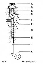
As long as it will go back into the correct position (both rotation and left/right), it's OK. If it won't go back easily (finger pressure), then remove the operating valve (hex plug on top above the adjustment lever, plus spring, distance piece & bearing ball) and lift the valve stem. (The stem is hollow, bend a paper clip to fit into the hole so you can lift it up.) With the stem lifted (or removed), you should be able to put the shaft back into position.
 
OP
KVH

KVH

Darth Vader
Country flag
Offline
The strange thing is that there doesn't seem to be a nice "seat" behind the collar for that O ring. It's almost as if it just sits there. There is a tight seat on the passenger side.

Also, and more importantly, I do have that shaft nicely back in place, through both ends of the OD case, but why don't I sense some sort of engagement or mechanical functioning when I rotate the shaft by hand. It just seems to rotate each way, meaninglessly. Inside the case something else is going on?

Sorry for the endless questions, but I also want to be sure I have the shaft in the correct position before I knock that pin back in place, up from the bottom. How will I know which side is "up" when looking at the little hole in the shaft where that pin goes? I should have marked it.

RANDALL THANKS FOR ALL THE HELP! THESE GREAT LITTLE CARS!!
 

TR3driver

Great Pumpkin - R.I.P
Offline
I don't have a photo handy, but as I recall there was just a little area on the cover that was machined flat for the O-ring to ride on.

If you still have the operating valve in place, then you should feel some resistance to turning the rod. The cam inside the housing (K in the diagram below) is supposed to lift the operating valve spindle (J) when the rod is rotated to the 'engaged' position (meaning the 3/16" hole in the adjustment lever would line up with the hole in the case, if you had the lever installed). The spindle doesn't move very much, perhaps 1/16" or so, but it should be enough that you can feel the force to compress the spring (B)under the plug on top (A).

Probably the best thing is to go ahead and remove the operating valve spindle, then turn the rod as far CCW (looking at the adjustment lever side) as you can. Then you should be able to drop the spindle back in place, and see that it moves a bit when you rotate the rod clockwise. Don't go too far or you'll have to repeate the process. Now you're close to the right position to install the adjustment lever.

Gotta run, more later, maybe.
 

Attachments

  • 26511.jpg
    26511.jpg
    32.4 KB · Views: 191
OP
KVH

KVH

Darth Vader
Country flag
Offline
Randall, WOW, that paper clip trick was great. The valve came right out, you were right about the cam being too far past.

Now I've got two other problems. Or issues:


1) There a nice o ring seat on the passenger/adjustment lever side of the OD. But the "seal" referred to in the manual on the solenoid side must be a machined seal because there is no room between the collar and the housing to squeeze an o ring into. The pinch lever won't go on if I put an o ring in that location.

Is it possible the manual and Moss are mixed up on this. I can't imagine "mashing" that o ring in that tiny space if that is what they both have in mind, but I guess I could try.

2) Also, with the adjustment lever now attached, in order to fit the 3/16 rod, I need to move the lever a very small bit, like about 1/32 inch. Does that sound right?


thx
 

TR3driver

Great Pumpkin - R.I.P
Offline
Well, what size O-ring are you using? I'm not certain what the factory put in there, it might have been a washer instead of an O-ring, but I know I used O-rings on both sides and mine have all gone back together.

The lever doesn't move by much, but 1/32" seems too small to me. ISTR mine was closer to 1/8" or maybe even 3/16". Did you put all the pieces back into the valve? The final check is to see how far the valve ball rises; on some units the spindle & cam are worn enough that the lever has to move farther than where the holes line up. See https://www.buckeyetriumphs.org/technical/AOD/AOD4/AOD4.htm for more details (although personally, I believe the "Healey" spec is correct).

PS, ISTR the O-rings were -011 (5/16" id, 1/16" thick) but it's possible I'm mistaken on that point. However, I grabbed one just now and it definitely fits along with the spacer and the lever.
 
OP
KVH

KVH

Darth Vader
Country flag
Offline
I'd have to squeeze the pinch lever closer together to make more room for that seal, and if I do then the collar will rub against it. I'm wondering if that's really the setup. That fitting in the case does look like a machined seal of sorts. I'm inclined to try pinching that lever closer together since I can't ever recall you being wrong.
 

TR3driver

Great Pumpkin - R.I.P
Offline
KVH said:
and if I do then the collar will rub against it.
Huh? The collar is supposed to rub against the seal, and be firmly against the lever.

Do you have the adjustment lever installed, and pressed firmly against it's seal?

Although on the one I checked, even with the adjustment lever as far away from the case as it would go, there was room for the O-ring, collar and lever on the other side.

How thick is your collar? Any chance it's the wrong one?
 
OP
KVH

KVH

Darth Vader
Country flag
Offline
Maybe you're onto something?

That collar I have is quite thick. I can measure it, but eyeballing it tells me it's just about 1/4 inch. It definitely protrudes out beyond the machined slot where it is supposed to fit. And, yes, I have the rod all the way in from the adjustment lever side.

By rubbing, I was concerned that a tight fit of a rotating part against a rubber seal would be a certain setup for quick wear.

There is no socket or slot for the o ring on the solenoid side. It would be mashed between the rotating collar and the casing, which would seem a bit primitive.

Is that collar supposed to have a recess for the seal???
 

TR4nut

Yoda
Country flag
Offline
It is rare that I disagree with Randall - in fact this may be the first time! But I'm certain the o-ring is captured between the plate and the main overdrive body - there is a machined recess for it on the back side of the plate.

See the Buckeye assembly instructions and they talk about the o ring installed before the solenoid plate: install doc
 

TR3driver

Great Pumpkin - R.I.P
Offline
Randy, you are 100% correct! I had forgotten all about that seal under the plate.

Don, my apologies for the misinformation. I know I put an O-ring there last time, but I guess it wasn't necessary.

Here's the spacer & O-ring I added on the outside:
DSCF0371.jpg


(My spacer measures closer to 3/16" (.192"))

And here's the O-ring on the inside:
DSCF0372.jpg
 
Similar threads
Thread starter Title Forum Replies Date
R TR2/3/3A Transmission leaks Triumph 29
Jim_Gruber Correct Transmission Oil for Datsun 210 5-speed Spridgets 1
Got_All_4 General Tech TR6 Transmission Troubles Pops Out of 3rd gear Triumph 2
mctriumph SOLD!! Tr7/ Tr8 transmission Triumph Classifieds 0
C TR6 Transmission Number Meaning Triumph 5
R 100-4 Transmission Austin Healey 1
S TR2/3/3A Rebuilding a tr3 transmission and second gear, Triumph 57
S TR2/3/3A turn a tr3 non-full syncro transmission into a full syncro Triumph 3
J TR4/4A TR4A automatic transmission conversion Triumph 6
Popeye TR4/4A Transmission noise - intermittent Triumph 22
D XK150 Transmission Input Shaft Jaguar 1
A TR2 Transmission overhaul Restoration & Tools 0
E General MG Transmission Fluid Level MG 2
B Transmission Gear Lockouts Austin Healey 8
K Putting a Getrag 5 speed OD transmission in a Jaguar Mkll ? Jaguar 4
AUSMHLY Transmission Noise Austin Healey 11
KVH General TR Transmission Problem Triumph 3
T Looking for "BillMs rear transmission mount" Spridgets 2
T For Sale Excellent Original 1968 TR250 Frame with Engine & Transmission Triumph Classifieds 6
D TR2/3/3A Torque for bolts back of transmission ? Pl Triumph 0
bighealeysource Side-Shift Transmission Austin Healey 13
D transmission conversion Other British Cars 1
PAUL161 T-Series Original transmission sold MG 2
KVH TR4/4A Assembling Transmission to Engine--Vice/Versa Triumph 4
BritBite Transmission Repair Austin Healey 8
AUSMHLY Transmission Bearing, Sealed vs. Non-Sealed Austin Healey 6
AUSMHLY BJ8 Transmission Gasket Austin Healey 0
AUSMHLY R & R BJ8 Transmission Bearings Procedure Austin Healey 1
AUSMHLY BJ8 transmission 3rd gear chipping Austin Healey 0
AUSMHLY BJ8 transmission mainshaft bearing force needed to install/remove Austin Healey 1
AUSMHLY BJ8 Transmission Oil Capacity Austin Healey 1
TR6Canuck For Sale 72 TR6 clutch and transmission Triumph Classifieds 4
N Ribcase transmission won’t engage 3rd or 4th gear Spridgets 19
N Sprite "Ribcase" Transmission Austin Healey 3
AUSMHLY Transmission Sliding Hub Plungers Austin Healey 9
AUSMHLY BJ8 Transmission Front/Rear Bearing Shim Austin Healey 2
AUSMHLY Denis Welch Pre-Load Transmission Washers Austin Healey 0
AUSMHLY BJ8 Transmission just rebuilt now has metal filings Austin Healey 10
S MGB Transmission cross member re-install MG 14
AUSMHLY Flushing the Transmission/Overdrive Austin Healey 7
AUSMHLY BJ8 Transmission Gasket Austin Healey 0
WHT BJ8 Transmission Installation Austin Healey 0
T Weight of BJ7 Transmission/Overdrive Austin Healey 10
T How to ship transmission from Canada to Rivergate in Tennesee? Spridgets 8
AUSMHLY BJ8 Transmission Gasket Sealer Austin Healey 18
A TR6 Installing differential and transmission Triumph 10
PAUL161 T-Series 5 Speed Transmission MG 85
PAUL161 T-Series Replacing Transmission MG 3
WHT Tremec T-5 Five-Speed Transmission Austin Healey 39
R TR2/3/3A Transmission Service TR-2 Triumph 58

Similar threads

Top