
-
 Hey Guest!
British Car Forum has been supporting enthusiasts for over 25 years by providing a great place to share our love for British cars. You can support our efforts by upgrading your membership for less than the dues of most car clubs. There are some perks with a member upgrade!**Upgrade Now**
(PS: Upgraded members don't see this banner, nor will you see the Google ads that appear on the site.)
You are using an out of date browser. It may not display this or other websites correctly.
You should upgrade or use an alternative browser.
You should upgrade or use an alternative browser.
TR4/4A TR4A Assembly by a rookie (me!)
- Thread starter Popeye
- Start date

OP
Popeye
Obi Wan
Offline
Thanks! (Please ignore the junk (multiple hobbies) in the background.) And thanks for the heads-up on Hylomar.Excellent workman-like procedures, Mike! Great progress too.
An alternative to RTV or that shellac (horrible stuff IMHO) is Hylomar Blue sealant. It remains a semi-solid over time and has done an excellent job where paper gaskets are used.
Offline
I'd be concerned if there weren't multi-interest items! Heck, I've a pair of downhill snow skis in the rafters and multiple slalom water skis propped against the wall. Bikes hangin' from hooks and two Linux servers running on a desk. All in my garage. Along with a 12" radial arm saw...Thanks! (Please ignore the junk (multiple hobbies) in the background.) And thanks for the heads-up on Hylomar.
OP
Popeye
Obi Wan
Offline
Quick update on oil pan bolt location: My above conclusions are incorrect; I confirmed the expertise of experts on the web:Also installed the oil pan, but still need to figure out where the long bolts go - as can be seen in the photo both are incorrect! (None of the bolts are torqued at this point - no blue marks.) After some late-night research, it seems one long bolt goes where the clutch slave cylinder reinforcing rod mounts, but not sure the other. Note: Most folks say to put the short bolt in the aluminum block at the front. However I found the blind threaded hole by the dipstick to have shortest engagement depth and put it there. (At the end of the day it probably is not too important... all bolts have sufficient thread engagement to hold the pan.)
(Not that I doubted wonderful folks like Randall; rather I like to confirm things, given car-to-car variability.)
1. Short bolts, #1: One 5/8" bolt should go in to the front aluminum sealing block. If the bolt is too long the bottom of the block can crack when the bolt is torqued. On my engine a 3/4" bolt fit, but barely. I am not sure what would have happened had I torqued it.
2. Short bolts, #2: On my engine, a short bolt was also needed for the hole adjacent to the oil dipstick; a 3/4" bolt bottomed out. (This bolt threw me for a loop - see #1 - as the spare parts only lists one short bolt and clearly #2 needed it.)
3. Long bolt, #1: I put a 1-1/4 bolt where the clutch slave support will mount.
4. Long bolt #2: I assume this is a carry-over from the TR4 which had an oil breather. I used a 3/4" bolt in this location (opposite the clutch slave support).
OP
Popeye
Obi Wan
Offline
Small update: replaced the oil seal on the tachometer drive shaft. A bit finicky, but ultimately straightforward once I understood how the parts are assembled.
I removed the setscrew (don't lose it, it's special). The brass bearing assembly has flats that a narrow wrench fits on to, and applying gentle torque got the bits apart. The brass bits split into two, held together with a pin. I drilled out the pin - not too easy given the relatively soft brass, and the two parts unscrew from one another. I replaced the oil seal (well greased), and re-assembled with blue Loctite. I will drill for a pin (likely in a different location), but first need to peruse the smallest pin I can find at Ace.
The pedestal was cleaned and painted, along with the water pump housing, fan extension, and pulleys (rattle can engine paint - unfortunately for full strength a 200F / 1 hour cure is needed, which won't happen until the engine is running - even then it won't be 200F).
Thanks for getting one of those brass deal apart. I have never taking one apart, but I do have one with something wrong with it. The gear slides back and forth or up and down in the pedestal depending on how I look at it. Perhaps the pin is broke. Where does the rubber seal go on the shaft? Oh the engine coming alone nice also
Thanks steve
Thanks steve
OP
Popeye
Obi Wan
Offline
Hi Steve,Thanks for getting one of those brass deal apart. I have never taking one apart, but I do have one with something wrong with it. The gear slides back and forth or up and down in the pedestal depending on how I look at it. Perhaps the pin is broke. Where does the rubber seal go on the shaft? Oh the engine coming alone nice also
Thanks steve
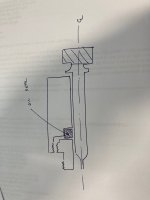
The pin connects the outside brass piece to the inside threaded piece. (In the upper picture of my post, the parts from the bottom are: the gear, the threaded inside piece, the outside piece. You can see where the pin hit the threads in the inside piece - the bright spot on the larger diameter threads.) If the pin broke, it would allows this piece to unscrew - I assume this would be reasonably obvious by looking at the parts.
The gear is not "locked" to the outside brass piece. It can be pulled out. The corresponding gear on the oil pump shaft keeps this one in place. (The setscrew on the outside of the distributor pedestal housing prevents rotation of the brass piece... it does not lock the gear.)
Below is a photo of the rubber seal installed. Metal side facing the oil side, and I used the threaded piece to push the seal home.
Hope this makes sense?
OP
Popeye
Obi Wan
Offline
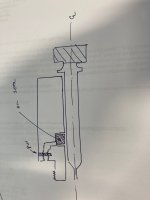
A missing seal would not allow any additional movement (the seal "grips" the shaft, so it adds friction). Basically, the rotating shaft is a sliding fit inside the brass bit... see attached chicken-scratch cross-section.Ok, so let me ask if the seal is missing then would the shaft go back and forth in the housing the thickness of the seal.
steve
Attachments
OP
Popeye
Obi Wan
Offline
Quick update:
I installed the distributor pedestal. I did not need any shins to get the proper gear lash, so I only used a thin coat of Permatex to install it (no gasket).
And, from another forum, I copied a “MacGyvered” (is that spelled correctly??) pushrod tube swaging tool using 3/8” flare fittings from HD and threaded rod. Tubes installed with loctite blue. Worked very well… hopefully no leaks when all is complete!
Next up: fuel pump rebuild using the “complete” kit from TRF.
OP
Popeye
Obi Wan
Offline
Good to hear! That is a replacement water pump my mechanic bought. I decided to send the original water pump to the Flying Dutchman for a rebuild (and upgraded impeller), and will keep this one as a backup.Love seeing that "Classic Gold" box. Haven't had a disappointment with any of the parts under that label. If ever there is a choice between that and a "generic," go with the blue box!")
On a related note, I bought the “better” fuel pump made in Italy for TRF. (Not cheap, but Albert Runyon seemed to do a good job when custom-making parts.) Turns out the pump that came on the motor was aftermarket (from Canada). Stripped threads on the inlet side were the proverbial final nail in the coffin! I’ll keep my eyes out for an original AC pump as a backup (I still have the rebuild kit if needed).
On to the oil filter cleanup. Most of the seals, etc. bits are unobtainium.
Offline
Those AC pumps were VERY common back in the day, fitted on about everything from tractors to LBC's. About the only variation was the shape of the actuating arms.
Concerning the seals, if you have a good bearing house in the area and measure I.D. & O.D. with thickness they may be able to match 'em. Look for the oldest guy on the counter for help.
Concerning the seals, if you have a good bearing house in the area and measure I.D. & O.D. with thickness they may be able to match 'em. Look for the oldest guy on the counter for help.
OP
Popeye
Obi Wan
Offline
Update:
1. I cleaned up and installed the oil filter attachment. I replaced the pressure setscrew ball and spring. (Original ball looked great. The spring had minor wear on the side, presumably from engine vibration). The oil pressure setscrew is sealed with loctite blue instead of lead - for now. The lead seal prevents adjustment, so I hope to get the pressure set correctly before using lead. Hopefully the loctite blue holds enough to allow this...
(Being a sucker for originality, I am staying with the cartridge filter and forgoing a spin-on adapter. Hot oil running down my arm be darned!)
2. I installed the "made in Italy" fuel pump from TRF. It looks really nice; the casting quality is excellent. Obviously time will tell if the reliability is good.
3. Installed the front pulley and fan, including fan bolt. (Again, forgoing a high-efficiency fan... see above "sucker for originality" comment!) I put anti-seize on the bolt, figuring it is (1) high torque, and (2) in a hot and non-oiled location. I torqued to 140 ft-lb, on the high side of recommendations; I figure the higher torque helps compensate for the lubricity of the anti-seize. (I was able torque the bolt because I removed the oil pan and blocked the crankshaft in place.)
4. When installing the oil filter housing, I had to slightly correct an opening in the gasket with an exacto knife. I did this with the gasket on the engine and of course the piece I cut out fell into the engine. Silly me! (I found the piece.) Lesson learned; I will re-attach the oil pan (with new gasket) AFTER everything else is buttoned up (temporarily installed to help keep things clean).
Anything to check "one last time" before I install the head? What are the odds I will remove the head prior to starting the engine? (Should I use the "good" ($70) Payen gasket, or just a "simple" ($20) copper gasket for the initial install - replacing with the good gasket later??)
The rocker arm assembly is off to California for a rebuild by Rocker Arms Unlimited. Distributor was received from Advanced (beautiful!), and the water pump is a few weeks out yet at the Flying Dutchman. Carburetors are probably still two months out at Joe Curto.
As an aside, I love the "organic" smell of the rosin in gasket shellac.... I know the Permatex / Hylomar compounds are more effective, but I spent the money on the tube of shellac and it just smells good. A great write up here: > CC Toolbox: Indian Head Gasket Shellac <.


.jpg")
1. I cleaned up and installed the oil filter attachment. I replaced the pressure setscrew ball and spring. (Original ball looked great. The spring had minor wear on the side, presumably from engine vibration). The oil pressure setscrew is sealed with loctite blue instead of lead - for now. The lead seal prevents adjustment, so I hope to get the pressure set correctly before using lead. Hopefully the loctite blue holds enough to allow this...
(Being a sucker for originality, I am staying with the cartridge filter and forgoing a spin-on adapter. Hot oil running down my arm be darned!)
2. I installed the "made in Italy" fuel pump from TRF. It looks really nice; the casting quality is excellent. Obviously time will tell if the reliability is good.
3. Installed the front pulley and fan, including fan bolt. (Again, forgoing a high-efficiency fan... see above "sucker for originality" comment!) I put anti-seize on the bolt, figuring it is (1) high torque, and (2) in a hot and non-oiled location. I torqued to 140 ft-lb, on the high side of recommendations; I figure the higher torque helps compensate for the lubricity of the anti-seize. (I was able torque the bolt because I removed the oil pan and blocked the crankshaft in place.)
4. When installing the oil filter housing, I had to slightly correct an opening in the gasket with an exacto knife. I did this with the gasket on the engine and of course the piece I cut out fell into the engine. Silly me! (I found the piece.) Lesson learned; I will re-attach the oil pan (with new gasket) AFTER everything else is buttoned up (temporarily installed to help keep things clean).
Anything to check "one last time" before I install the head? What are the odds I will remove the head prior to starting the engine? (Should I use the "good" ($70) Payen gasket, or just a "simple" ($20) copper gasket for the initial install - replacing with the good gasket later??)
The rocker arm assembly is off to California for a rebuild by Rocker Arms Unlimited. Distributor was received from Advanced (beautiful!), and the water pump is a few weeks out yet at the Flying Dutchman. Carburetors are probably still two months out at Joe Curto.
As an aside, I love the "organic" smell of the rosin in gasket shellac.... I know the Permatex / Hylomar compounds are more effective, but I spent the money on the tube of shellac and it just smells good. A great write up here: > CC Toolbox: Indian Head Gasket Shellac <.
Offline
That Indian Head article is hilarious!
"...take down the bottle of Indian Head gasket shellac, open it, take a little whiff, close it and put it up, and proceed on your repair with renewed concentration and back in the right headpsace."
My grand-dad used it, I can conjure up the odor in my mind today! And I remember disassembling a two-stroke Lawn Boy engine he'd used it to GLUE the carb on with. Swore I'd not be needing it for anything I intended to keep.
OP
Popeye
Obi Wan
Offline
Thanks for the advice. I have been debating when is best to paint the remaining exposed surfaces. I've done most of the bits with VHT spray paint - but may switch to POR-15 brushable for post-assembly painting and touch-up. (With the usual question, is masking faster than brushing??) Not to mention, brushing allows the the the zinc-chromate plated bolts to show a bit of bling!It looks great. I would paint any bare metal like in the front because somehow even with an open crankcase engine, they find a way to rust.
steve
OP
Popeye
Obi Wan
Offline
It has been a while since I posted - and have not made too much progress. I installed the head, using the Payen gasket and copper spray. I made some “Dr. Entropy” alignment studs from the old studs - extremely helpful! (See here: > Came across these "tools" <)
I've also painted miscellaneous exposed bits of metal.
Next step is to take the engine off the stand. I built a rolling cart out of 2x4s that fits around the oil pan.
From here I will mate the flywheel (ensuring it is flat) and clutch. I had the clutch and flywheel balanced by my local machine shop. Next is a bench test of the transmission OD (need to build a test stand...), and then marry the two in holy (lowercase "h" ) matrimony and hopefully many miles!


I've also painted miscellaneous exposed bits of metal.
Next step is to take the engine off the stand. I built a rolling cart out of 2x4s that fits around the oil pan.
From here I will mate the flywheel (ensuring it is flat) and clutch. I had the clutch and flywheel balanced by my local machine shop. Next is a bench test of the transmission OD (need to build a test stand...), and then marry the two in holy (lowercase "h"
) matrimony and hopefully many miles!
Last edited:

Online
WOW, you sure did a great job. I'm about ready to start my full engine rebuild, and have some questions, a lot. I hope you don’t mind, but I’m a bit nervous after letting my block sit for 2 years:
a) Your crank pulley and timing gears were not marked, right? Looking at your set up, can you explain just a bit further? For instance, when you measured 110 after TDC for the one valve fully open, what did you do with that information? What adjustment did that lead you to? In other words what readings do you take from the wheel and how do those translate to another adjustment you make? I actually didn't find the Macy's article that helpful (to me).
b) those new pushrod tubes--did you use that flaring tool for the fit? And only because the old tubes were ruined somehow, or missing?
c) what issues did you have with the thrust washers and bearing clearances, or was that part done at the shop?
d) just being an old grandma, did you remember the washer that goes ahead of the cotter pin on the timing chain tensioner?
e) what kind of gasket sealer did you use on that front engine cover? A friend swears by some “Motorcraft” gray product. I don’t recall if you’re supposed to put sealer on both sides of that gasket—how did you handle it? I'm wondering what your criteria was for choosing red vs. blue RTV, or is that blue Hylomar I see there? Related to this, did you make much use of Permatex Aviation or Permatex High Tack?
f) you did not use a solid copper gasket, correct? You used a composite one, copper or some alloy sandwich gasket?
g) with the new sleeves and figure 8 gaskets, either the clearance is .003 to .005, or close, or its not. What can you really do about it? I’ve always been within clearance, but wonder the workaround is if not. You sealed the sleeves with WellSeal?
h) about that wood cradle for the engine—to lower the engine and attach the transmission. Can I see a pic?
(I can’t recall how I handled that last time, but I’m fairly certain I rested to engine on blankets to avoid pressure on the oil pan. Or I may have left the hoist partly under tension. I do recall feeling that everything would have been much easier, including sliding the engine/transmission back into the car if I’d just left the oil pan off and installed it later from underneath. Any thoughts on that? Too convoluted for the payoff?)
The oil pan clearance to that front frame member is very tight on reinstallation of the engine/transmission, and I did scrape a bit.
i) did you end up using the Viton rear main seal? Any issue there?
j) your fan damper looks custom? Am I wrong? (though you kept the stock fan)
Well, I’ll be lucky if you have the patience to review, but any thoughts or experiences would be appreciated. Love seeing these cars restored. They deserve it, and the engineers who put that Triumph manual in print ought to be celebrated eternally.