Aloha,
Below is the text of an article written by Clive Elsdon and a link to a website with the complete article that includes photos,
link:
https://www.tr-register.com.au/files/technical.htm
Sidescreen Control Head
(No, not a description of the driver… it's the bit with the horn push and indicators!)
Introduction:
Those of you that own a TR2 or TR3 will know that the Control Head can be frustrating to say the least, and very expensive to replace at the worst. The main problem that I have had is the mechanism jamming causing the whole unit to turn with the steering wheel. This can damage the very heart of the unit and also damage the wiring inside the Stator Tube. Whilst replacement wiring is available at a reasonable cost a damaged unit cannot be repaired due to the fact that the spare parts are not usually available. A complete unit from one of the suppliers will cost about £120.00. You might be lucky and come across a good second hand one, but it is likely to set you back about the same.
As I have said the replacement wiring is readably available, what isn't is a guide to installing it. This unfortunately requires the unit to be stripped down to it's basic components! I've never counted how many of these there are, but it's a lot, and the whole thing is a bit of a jack-in-the-box when you take it to pieces!
Removing the Control Head from the vehicle:
(Description is based on a 1954 TR2)
Firstly undo the three hex drive grommets in the steering wheel boss. You then have to go to the front of the car and disconnect the four wires. Now undo the large nut on the front face of the steering box. This will reveal an olive, just like a piece of plumbing, and the oil will begin to run out of the steering box. Thread the nut and the olive off the wiring and store safely. Once you have done this you should be able to go back into the cockpit of the car and extract the whole assembly from the steering wheel. The whole thing is about 5 feet long. It is possible only to partly withdraw the assembly and work on it in-situ, however experience has taught me that the rest of the operation is a dining room table job in warmth and good light! For more detail of this part of the operation refer to your Workshop Manual.
The Control Head removed complete
Disassembling the unit:
The next stage is to remove the horn push and the front face. This is done quite simply by
Rear view of Control Head Assembly
unscrewing the three large screws on the reverse of the unit. Once the screws are undone the front face will fall away, together with the horn push, the horn spring and a locating button that sits in the centre of two brass contacts mounted on a piece of circuit board type material. There is also a brass contact plate on the rear of the horn push button. This should be stuck in place but sometimes I have found that the glue has failed. The button, which retains the horn push spring often remains in place. It is usually a tight, fit hence the reason it does not appear on the next photograph.
Removed Components
Front view of assembly with face removed
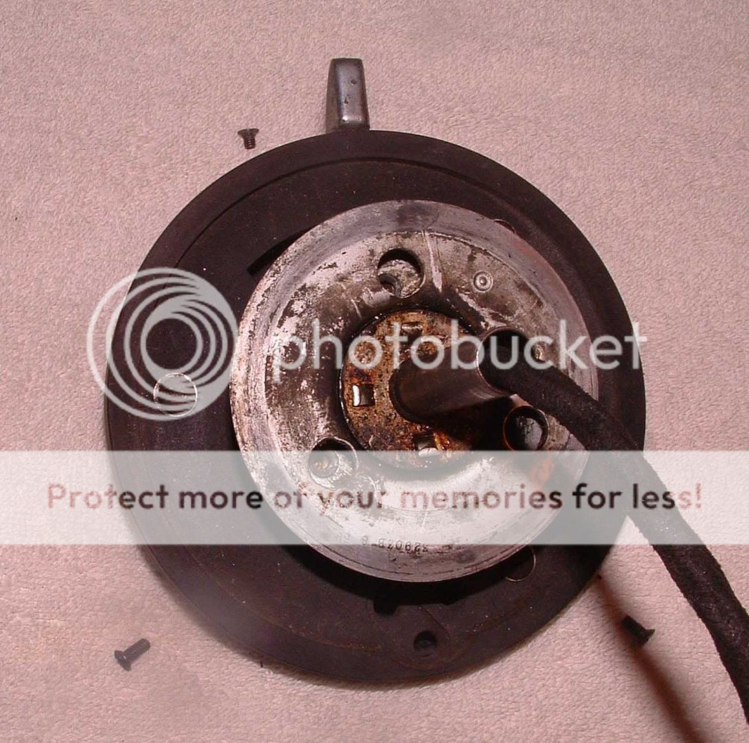
Next you need to undo three screws in the rear of the unit, to give you access to these you must line up the three holes on the back plate with the screws. Once these are removed the
Rear view showing holes aligned
control head is free to be pulled away from the backing plate, but be careful of the wires, which are still passing down the stator tube. (Note: The stator tube does pull out of it's push fit coupling with the backing plate, however, I have always found it easier to work on it with the tube attached.)
Rear view of Control Head removed from Backing Plate, note the three screws!
Now we are about to start on the bit where it all springs apart! On the front face there are two brass screws, which pass through the Removing the Brass Screws
circuit board type material and the two halves of the remaining unit. They also pass through one other component. In one case it's an end connection on a wire and in the other case it's a lug on a brass ring. The screws are secured by brass nuts on the reverse side. Both these screws must be removed, this frees the brass horn contacts from the front of the unit. Once the operation is complete the brass ring on the rear will also be free and you will have a loose brown and black wire! If the button in the centre of the horn contacts had not come away previously, it will have done now.
The components just removed (including the button that retains the horn push spring
The brown and black wire freed
The Brass Ring freed also
This last action will have revealed one remaining brass screw holding the two halves of the unit together. You will note that once you remove it that this screw is shorter than the other two. The removal of this screw results in the whole thing springing apart, so it is advisable to hold the two halves together and release them as slowly as possible!
The remaining brass screw
There are a number of small parts inside, and it is impossible to separate the two halves without these falling out!
The remaining components laid out
It's important that you check off the components that have come out, they are all essential! Excluding those we have already removed there should be:
1No. Centre pivot with thumb lever [a]
1No. Curved metal guide
2No. Washers [c]
2No. Long Springs [d]
1No. Short Spring [e]
1No. Brass Contact [f]
1No. Medium length spring [g]
1No. Wheel holder [h]
1No. Wheel [j]
2No. Hinged followers [k]
1No. Casing [l]
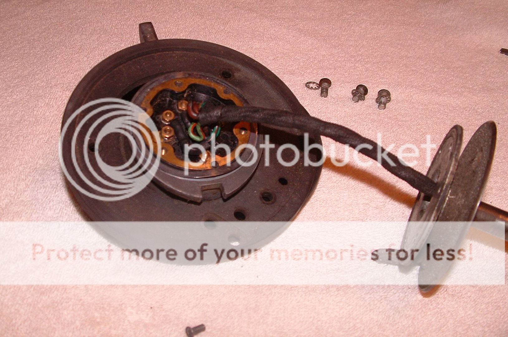
On the other hand we have circular moulded component still attached to wiring. These wires are released by removing the three remaining nuts on the back of the unit.
Front view of unit
The order of wires, from left to right, viewed from the rear is white body with green stripe,
Rear view of unit with the three remaining wires attached
green body with brown stripe and finally green body with red stripe. For those who want to know, these are your indicators! There is also a metal ring left on the unit, it can just be seen inside the circumference. It can be seen removed in the last picture of this section. I won't bother including a picture of the wires removed, and the description of the re-assembly will assume that these have already been re-attached.
 Hey there Guest!
 Hey - did you know if you click on the title of a thread it will take you to the first unread post since you last visited that thread?
 but were afraid to ask:
  STOP!! Never post your email address in open forums. Bots can "harvest" your email! If you must share your email use a Private Message or use the
  smilie in place of the real @
 Pretty Please - add it to our Events forum(s) and add to the calendar! >>

 A friendly reminder - be careful what links you click on here. If a link is posted by someone you don't know, or the URL looks fishy, DON'T CLICK. Spammers sometimes post links that lead to sites that can infect your computer, so be mindful what you click.