• The Roadster Factory Recovery Fund - Friends, as you may have heard, The Roadster Factory, a respected British Car Parts business in PA, suffered a total loss in a fire on Christmas Day. Read about it, discuss or ask questions >> HERE. The Triumph Register of America is sponsoring a fund raiser to help TRF get back on their feet. If you can help, vist >> their GoFundMe page.
  • Hey there Guest!
    If you enjoy BCF and find our forum a useful resource, if you appreciate not having ads pop up all over the place and you want to ensure we can stay online - Please consider supporting with an "optional" low-cost annual subscription.
    **Upgrade Now**
    (PS: Subscribers don't see this UGLY banner)
Tips
Tips

Crane XR700 Installation Problem

bailee2

Jedi Hopeful
Offline
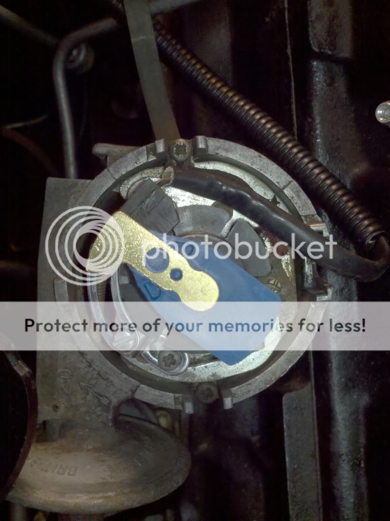
2011-02-27_15-18-33_387.jpg


Installed Crane XR700 and cannot get the the engine to fire.
Verified by the #1 plug not showing a spark at the plug.

12VDC is at the coil. Ground confirmed. 6 cyl rotating ring is pushed down all the way, clearance between the optical sensor and the rotating ring is ok.

I am not sure if the optical sensor is correctly posiitoned.
I it is possible to look at this pic and see if it looks correct would help. #1 cyl was at TDC. Rotor is in correct position but is the optical snesor correct as this is as far as it can be moved.

The instructions are not clear if the optical sensor has to be lined up with the center of the rotor at TDC.

I used the Condensor mount hole to mount the arm which mounts the sensor bracket. Another pic of a known working circuit may help.


Thanks.
Arlie
 

SkinnedKnuckles

Jedi Trainee
Offline
The optical sensor can actually use any of the slots to trigger the spark - it doesn't have to use the one at the #1 position. A clue is that the sensor support arm is fully extended. Try pulling it back so that the the preceding slot is the trigger and there is room for adjustment.

Also, you'll want to drill a hole in an old distributor cap at the #1 cylinder electrode for the "phasing" as shown in the instructions.
 

mallard

Luke Skywalker
Country flag
Offline
I agree with Brent, also the hole in the cap helps. I should still have the instruction sheet if you need one PM me.
 
OP
B

bailee2

Jedi Hopeful
Offline
The instructions I received does not mention "Phasing"
any instruction on that step would really help.

What are you looking for and how do you adjust the trigger.
I have an old cap to set this up. The trigger is fully extended now on the bracket. Are you loioking for a spark
as you move the trigger?

Thanks.
Arlie
 

TR3driver

Great Pumpkin - R.I.P
Offline
One thing to check is that the backside of your rotor is not hitting the optical pickup. I fought with my Crane XR3000 for over a year before I finally figured that one out! The rotor had a "counterweight" molded into it that was whacking the pickup and causing all sorts of erratic problems.

If your box has the LED on the end, then the installation instructions are on Crane's web site: https://www.cranecams.com/uploads/instructions/90000700.pdf
(Phasing instructions are on pages 14 & 15.)

I put up a copy of the old non-LED instructions here:
https://docs.google.com/viewer?a=v&p...kNWIy&hl=en
(Phasing instructions on page 14)

What voltage do you see on the ground side of the coil (with the yellow wire from the Crane module)?

Are you sure the module has both power and ground? Have you double-checked that the pins in the Molex connector are in the proper place, and not pushed back?
 

DNK

Great Pumpkin
Country flag
Online
Randall, looks like the correct button.
You can only use real Lucas style buttons with that.
For sure DO NOT use a Bosch.
 

Sarastro

Obi Wan
Silver
Country flag
Online
That business about "phasing" is pretty simple in concept. It just means that you need to position the sensor so that, when the unit fires, the rotor is in position pointing to a plug-wire terminal on the cap. If this doesn't happen, no way will the car run.

So, turn the distributor and watch the LED on the box to tell when it fires. Then, take off the cap, note the position of the rotor (make a mark on the distributor body if necessary), put the cap on and make sure that the mark coincides with a plug terminal on the cap. Unless you made a special effort to make sure of this, it's probably not right.

Of course, if you don't see the LED light up as described in the instructions, that means something is miswired or otherwise not working.
 
OP
B

bailee2

Jedi Hopeful
Offline
Thanks all.
I will retry later this week. Work thing.....

I appreciate the links.

This is for a TR6 application.

The rotor and cap are new Heavy Duty ones from BPNW.

The sensor is the LED type.

I will respond as soon as I can. Thanks.

Arlie
 

AndreL

Freshman Member
Country flag
Online
Arlie,
I just finished installing the same component on the same car.
Astonishingly it worked for me.

I installed the optical trigger ~4 times at two locations facing opposite directions before I figured the optimum way. Sadly I don't have a digital camera so I could show you.

I used a different location for the mounting foot. Looking at your photo, I used the points plate screw hole located at 10 o'clock for the base of the mounting foot. The top of the foot ends up at 9:15, the exact angle dictates how deep the shutter goes into the throat of the optical trigger.
The mounting arm goes counter-clockwise until the vertical segment of the arm ends up at 7 o'clock. Practically reverse to what you have.

I drilled the rivet out of the terminal bush & lead, enlarged the hole slightly and fitted the new wire snugly through it.

The optical trigger bottoms out against the points plate and that seems to be the right height for the shutter in the throat of the optical trigger.

I mounted the ground wire to the coil bracket to keep the wires together and used small screws to fastened the factory loop-connectors of the yellow and red wires to the coil.

I triggered the spark many times to locate the optical trigger at the leading edge of the gap in the shutter as explained on page 14-3 under Optical Trigger Adjustment Procedure.

Then I used an old distributor cap, drilled a 1/2 inch hole at number 6 terminal, attached the timing light at the 6th plug('cause it's easier to see 6). The rotor dog and terminal lined up nicely.
The old distributor cap is brittle and while drilling I did take a piece out of it when I skipped many drill sizes.
I just glued it together for the test.
It may require fine tuning but so far it sounds normal.

André
Toronto Triumph Club
 

3798j

Darth Vader
Bronze
Country flag
Offline
Here are two photos of a working installation (GT6). Have you had a chance to work on yours? Randall's comments about the pins in the Molex connector getting pushed back (and not making contact) is exactly what happened to me.

IMAG0064.jpg


IMAG0063.jpg
 
OP
B

bailee2

Jedi Hopeful
Offline
Update:
Project is officially in the mystery ignition status.

Still no spark. Phasing complete.

Suspect the Lucas Sport Coil. From what I can tell this coil has an internal Ballast Resistor by the internet but my Ohms check showed "0" ohms. Coil is about a year old.

<span style="font-weight: bold">Could it be</span> there are two types of Super coils and mine is minus the built-in ballast resistor?

I should still get a spark at the plug whether it has has a ballast resistor or not (assuming).
Re-checked the Molex pins and htey are contacting each other.
Hangin in there with the Six.
Arlie
 

TR3driver

Great Pumpkin - R.I.P
Offline
Actually there is (or at least was) a "Lucas Sports" coil without the internal ballast. But even so, you should be seeing around 1.5 ohms. If it is really zero, then either your ohmmeter is goofy, or the coil is shorted.

It might be possible that the XR700 is shutting down due to excess current of no ballast, but it seems unlikely to me. Their output stage will handle that much current for awhile, and then it shuts down completely after just a few seconds if the engine isn't turning. (For the box with the LED on the end, earlier ones didn't shut down.)
 

big6

Jedi Trainee
Country flag
Offline
What is the condition of the braided ground cable between the distributor body and the point plate? I had a Spitfire at one time and the internal distributor braided ground cable was the ignition problem.
 

Sarastro

Obi Wan
Silver
Country flag
Online
As I remember, the Crane requires a coil of 4 ohms or more primary resistance. If you are measuring zero, something is definitely wrong. Usually, you won't see zero ohms even if you touch the probe tips together, as the probe wires have some small resistance, and usually there is an "offset"--a nonzero reading when it really should read zero. If there is a small offset, usually less than an ohm, you have to subtract this from the measurement.

You should be on the lowest-resistance scale of the meter. Are you sure you have the ohmmeter on the right scale?
 
OP
B

bailee2

Jedi Hopeful
Offline
It's Saturday afternoon and the TR6 is purring.

Thanks to all that posted their help/advice.

Coil was ok. It does have a ballast resistor. Just changed the Ohm setting.

The issue was a brain dead XR700. Tried a known good one and it works fine. Crane emailed me a RGA to send it back.

Cheers!!!

Arlie
 
Similar threads
Thread starter Title Forum Replies Date
G Crane XR700 Electronic Ignition / BT7 Austin Healey 6
Lin Crane or Fast XR700 Electronic Ignition Austin Healey 4
Lin Checking static timing for a 1275 with Crane XR700 ignition Spridgets 0
RickB MGB Crane Cams XR700 Fireball - wet conditions? MG 7
matmire Crane XR700 electronic ignition, now FAST XR700. Spridgets 12
P Allison/crane xr700 install Triumph 1
Z Crane XR700 help needed, car won't run Triumph 27
PAUL161 T-Series Crane Cam MG 0
B Crane Cams Electronic Ingnition Austin Healey 9
Marvin Gruber TR5/TR250 Pertronix vs Crane electronic ign Triumph 1
PAUL161 General MG Crane Electronic Ignition MG 9
DNK Crane Ign MG 6
1 MGB-GT Engine hoist/crane boom length? MG 17
PAUL161 Hap, Crane cams? MG 6
bighealeysource Anyone using an Allison or Crane on your Healey Austin Healey 7
dklawson Bad Economy Forces Crane Cams to Shut Down Spridgets 7
dklawson Economy Shuts Down Crane Cams Triumph 5
T lotus excel ignition - can i run a crane hi-6 ? Lotus 0
S Pertronix Ignition VS Crane/Alisson Ignition? Triumph 7
bmurphy7369 Wiring help needed badly... 1975 XJ6 Crane setup.. Jaguar 8
bmurphy7369 XJ6 SII 1975 with Crane Ignition dies when warm Jaguar 10
tosoutherncars Crane ignition question Spridgets 15
A Crane vs. Pertronix ignition Triumph 9
Z RVI Tach w/ crane ignition? Spridgets 2
T MGB Static timing a MGB w/ a Crane Electronic Ignition MG 5
Atrus Crane/Pertronix Ignition Question Spridgets 11
Sarastro Crane electronic ignition installation Spridgets 3
bravenrace Pertronix or Crane? TVR 8
Michael Oritt Crane XR3000 ignition system Racing 4
F Re: crane xr 700 optic ignition system question MG 10
V TR6 TR6 Crane Cam Grind# S-264-C Triumph 2
L Spark Plugs with Crane Ignition MG 10
A Help with electronic ignition [Crane] MG 11
R Crane Cams Electronic Ignition Module Austin Healey 5
K Crane Cam Spridgets 4
C Pertronix versus Crane ignition kits ? MG 7
Y Crane Vs Pertronix Austin Healey 5
G Pertronix vs Crane Ignition MG 18
H TR6 1974 tr6 allison xr700 Triumph 12
K Troble shooting Allison/XR700 Ignition Restoration & Tools 9
jvandyke pointless ignition XR700 vs. Allison Spridgets 12
A MGB Seat Cover Installation MG 1
Sarastro TR4/4A Convertible top installation problem Triumph 12
D BJ8 Top Installation Detail Austin Healey 3
zoohow BN4 Top Frame Installation Austin Healey 1
R MGB side chrome installation MG 4
P Alternator Installation Pic Austin Healey 4
VeeCee MGB 1974 MGB Roof Installation MG 0
Texas TR3 TR2/3/3A Convertible top webbing installation help? Triumph 5
Bruce 3000 Rally Grille Installation Austin Healey 5

Similar threads

Top