• The Roadster Factory Recovery Fund - Friends, as you may have heard, The Roadster Factory, a respected British Car Parts business in PA, suffered a total loss in a fire on Christmas Day. Read about it, discuss or ask questions >> HERE. The Triumph Register of America is sponsoring a fund raiser to help TRF get back on their feet. If you can help, vist >> their GoFundMe page.
  • Hey there Guest!
    If you enjoy BCF and find our forum a useful resource, if you appreciate not having ads pop up all over the place and you want to ensure we can stay online - Please consider supporting with an "optional" low-cost annual subscription.
    **Upgrade Now**
    (PS: Subscribers don't see this UGLY banner)
Tips
Tips

Uh Ohh, Oil All Over The Floor

vette

Darth Vader
Country flag
Offline
Bob, I can see where you have the PCV valve on the drivers side of the "tee" fitting and that is plumbed to the small brass 3-way "manifold" and then the small tubes go into your carb flanges to provide suction from both intake streams, and I think that is pretty nice. But where is the other side of the "Tee" fitting going? If it is going down to the engine side cover plate as the original Healey design did then I'm ok with that except that does not allow for air entry as you said yourself. BUT, IT DOES HAVE AIR ENTRY IF THE OIL FILL CAP IS VENTED.
 

vette

Darth Vader
Country flag
Offline
Ray, Thank you for the explaination. If I may add that I thought the hose on the right had a PCV valve in it where it entered the intake manifold and I see your concern about adding one. But I must say that you do not have a recirculating system. The hose going into the intake manifold is just providing a suction port for the brake booster and as such is out of the equation for crankcase venting/recirculating. If as I understand you that the hoses on the "tee" fitting are installed the same as the original Healey layout, then the hose on the passengers side (right side) of the "Tee" fitting goes down to the engine side cover plate (as original) and the hose on the drivers side (left side) of the "Tee" fitting goes to the catch can and from the catch can there is a hose to the carb air cleaner. I'll go back to my original premise in that there is no suction or recirculation there. The carburator air cleaner is not a suction, it is just a vent. And yes oil and fumes do get up there because it is acting as a two way street and the turbulence in the crankcase is pushing the crankcase atmosphere out any vent it can get. Your catch can is doing what a catch can should do and that is blocking the oily atmosphere from getting to the carburettor. The orginal Healey system does not allow very much venting because the hose from the engine side cover and the "Tee" fitting is acting as a two way street and can't provide enough volume to really vent the crankcase. But also too the Valve Cover fill cap is vented.
 

vette

Darth Vader
Country flag
Offline
Hutchster, I apologies for what I may have done in possibly Hi Jacking your thread. But going back to your original query, I believe that if there was an opening and filter on the side of the front area of the valve cover, as was your previous design, that it most certainly would blow oil out of it. Especially if the original Healey hose and vent system was still in place, because the original Healey system does not provide very good venting. As I believe Ray said previously, go back to the original Healey layout and see how that works. As Mert and I have both said, you can put a small 2" round, 5/8" nipple K&N filter on the left side of the "Tee" fitting for the first up grade to improve the system instead of the hose to the rear air filter.
 

RAC68

Darth Vader
Offline
Vette,
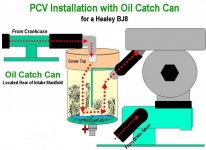
The oil catch can is presently installed in my car as a means of intercepting and extractingheavy oil/noxious vapor from being drawn into the rear carburetor/air cleanerfor a more controllable combustion mixture (see below). Engine ventilation flow is as original with no added vacuum drawn.

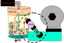
Oil Catch Can.jpg Figure 9.jpg

The second picture shows my original objective of installing a PCV gated into the manifold vacuum to produce low pressure within the engine and extract noxious oil/gases. As said before, Bob's configuration would allow for the PCV to draw its vacuum equally from both carburetors and leave the manifold port free for the brake booster.

As I understand, the PCV system requires the oil filler cap and dip stick to be sealable when closed. This allows for a mild low pressure to be drawn within the engine and by the PCV and the extraction of internal blow-by gasses to be extracted.

Hutchster,
After evaluating the condition of your valve train and after checking the engine under an original configuration, including making sure that both the oil filler cap and dip stick are not sealed when closed, have you found anything further? The installation of an oil catch can could assist in the extraction of a reasonable amounts of oil and heavy vapor. However, the amounts of oil being expelled seems to be far greater then could be handled reasonably so the cause and location must be addressed.

Ray(64BJ8P1)


Last edited:
Country flag
Offline
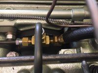
Here's a closeup of the 'manifold' (just a 3-way brass 'T' fitting):

IMG_1181.JPG

The builder was initially going to tap the manifold for the fittings at the carbs, but thought better of it. This way, all work is reversible (though the phenolic insulators ain't cheap).

Just finished final tuning; if the weather breaks I may get her out on the road for the first time since the rebuild today. Engine revs better than it ever has.
 

vette

Darth Vader
Country flag
Offline
Ray, i understand your layouts and I believe an oil catch can in line with a PCV valve into the intake manifold would be a viable method. But I have never understood the reason that people believe the oil fill cap and the dipstick tube should be sealed. If the intake manifold is going to pull air via the PCV valve from the crankcase why do so many people think that the crankcase has to be under a vacuum. The object is to move air not to lock it up into a vacuum. The reason that there is a vacuum on a brake booster circuit is because it is a closed circuit that does not move air it just wants a vacuum on the diaphram and the intake manifolds sucking can do that. The same goes for the distributor advance mechanism. It not moving air, it just needs a vacuum. But the crankcase you want to move air. If your going to pull it out, fresh air has to come in. the original PCV systems on American V8s in the late '60s and '70s had vented oil fill caps. The circuit on my 1970 Corvette has the PCV valve in the drivers side valve cover and the hose from the PCV valve goes to the carburettor throttle plate. That is the suction side. The other end of the circuit is on the passengers side valve cover and it is a hose from the valve cover stuck into the air cleaner. Inside the air cleaner at the open end of the hose is a steel wool and wire mesh filter which is used to block oil fumes that inadvertently get pushed towards the carb. But that hose in the air cleaner is the air entry point to the crankcase. You can see that the system has outside atmosphere on the passengers side valve cover entry down thru the drainback holes in the head to the crankcase and pulled up thru the drain holes in the drivers side head to the drivers side valve cover and the drawn thru the PCV valve by the suction of the intake manifold at the bottom of the carb into the intake stream and burnt with the combustion process in the cylinders. There is an open end where the air comes in and a pulling end at the PCV valve.
so this idea of sealing the crankcase everywhere other than at the PCV valve is ridiculus. Also know that there are times when the PCV valve is closed. Where does the air in the crankcase go at those times. If your crankcase is sealed to the max, then you build pressure and probably cause leaks. It you crankcase is open at one end then at least it is partially vented during the period that the PCV valve is closed. So how much of the time is the PCV valve closed? As you know it depends. It depends on engine speed, throttle position and the calibration of the PCV valve. And as I heard you say before and I agree, who knows what calibration our PCV valves are. There is usually max vacuum at idle and at high rpms. In between it is a crap shoot.
 

vette

Darth Vader
Country flag
Offline
Just for hick-ups and giggles. What is the best crankcase ventilation system? Ans: No crankcase at all. Just imagine the very early engines. Many did have open crankcases, the rods and main bearings were visible, out in the open. The oiling system had what I think was called, a positive loss oiling system. Meaning all the oil just drained out on the ground. It gravity fed down thru drilled holes and orfices in the engine and when it got to the bottom it just dripped off. They didn't have problems with pressure in their crankcases. Then some genius said, gee we're going to ruin our environment. We have to walk thru this stuff and the ladies will get their peticoats blackened and greasy. Probably a woman started it. So the man genius decided to devise a method where he could keep the lady folk happy. He enclosed the lower end of the engine with some tin and called it an oil catch pan. Well this got shortened to just oil pan for simplicity sake. But now that the ladies were moderately happy he realized that his new invention was creating pressure at the bottom of the engine and instead of the oil just dripping harmlessly unto the ground, the pressure in his oil pan was causing the oil to get pushed thru every gasket and orfice it could find and really messing up the top of the engine as well. So he decided to put a whole in his new oil pan, only it had to be above the main oil level, but since many of the early engines of the day where In-line 4, 6 & 8 cylinder engines he decided to put the hole in one of the engine side cover plates that effectively vented the crankcase. and he discovered that if he put a tube from the hole in the side cover down to a point just below the main undercarriage of the vehicle and cut the tube with an angle cut at the end, then that would create a draft when the car was moving. Hense we now had the down draft tube or the "Road Draft Tube". Well that system worked dang well thru the 1900s until about the 1960s. then the some what happy ladies began to get somewhat more unhappy because even though their pettycoats were pretty clean for more than 50 years they started to smell something. By Golly, this won't do, she could smell the oil and fumes coming from that darn Road Draft Tube. If he doesn't fix this, she won't go out on those week-end road trips with the Sporty Car Crowd. And he realized that the Road Draft Tube was kind of ruining the Duck hunting because all the ducks were being found down by the beaches just smothered in black oil. So he decided to just plug up the road draft tube. But that created the problem of pressure in the crankcase again. So he thought, if I could just suck out all the bad stuff from the crankcase and make it disappear then she would be happy and the world of Duck hunting would be safe again. Should he install a suction pump???? Ah ha, but he had a suction pump, it was the engine itself. So he stuck a hose from the crankcase into the intake manifold and wow did it ever suck. It sucked alright, until it stalled the engine. Too much gunk going into the cylinders. He eventually fixed that my installing a PCV valve into the hose going into the intake manifold, this effectively timed the amount of gunk going in and he redesigned the piston rings so that there wasn't as much gunk in the crankcase to begin with. Now all is happen again, ...... until we decide that our old engines don't work like new engines and by golly we want them too. Just take the oil pan off, the top of the engine will look beautiful. Cheers :cheers:
 

GregW

Yoda
Platinum
Country flag
Offline
But I have never understood the reason that people believe the oil fill cap and the dipstick tube should be sealed. If the intake manifold is going to pull air via the PCV valve from the crankcase why do so many people think that the crankcase has to be under a vacuum.
I think some people are trying to stop an oil leak at the rear crank seal. By sealing the dipstick and filler cap, air is drawn into the case through the seal area. Pulling the oil back in.
 

RAC68

Darth Vader
Offline
Hi Vette,

I totally AGREE that the oil filler cap and dip stick should be Vented and NOT sealed.

I did find paper notes that indicated the amount of blow-by during initial experimental installations was found to be greater than anticipated at Speed when the amount of vacuum was at its lowest. Upon returning home after a run, the few that initially experimented with a PCV installation, found various amounts of oil had been pushed out of the filler cap and dip stick to cover their engines. Seals were installed onto the oil filler cap and dip stick to reduce this condition and increase directional gaseous flow during times of minimal vacuum with high blow-by (at speed). The results of those actions was to improve the oil blow-by retention and leverage blow-by pressure to add additional force to exhausting gases through the PCV.

Keep in mind that a normal PCV configuration does utilize a vent that must be placed as far as possible from the PCV and is needed to allow 2-way ventilation:
1. Supply Fresh Air at Idle with High vacuum and Low blow-by
2. Exhaust Blow-by at Speed with Low vacuum and High blow-by

When considering a proper PCV installation (assuming we can identify a proper PCV valve), I would also install an Oil Catch Can on the “T” tube prior to the PCV to extract any heavy oils/vapor from flowing through and contaminating the PCV. I would gain vacuum to the PCV in the same way Bob has, through tubes tapped into both carburetor spacers. Finally, I would install a vent tube into a sealing oil filler cap and connect it, vial tube, to an air filter in a similar way as with the originally rear (could be installed on the front carburetor) to supply either clean filtered air or direct expelled blow-by for combustion...which ever is called for at the time.

Although I feel this configuration would work, as Derek had posted, it is too complex and prone to unintended consequences for me to install on my Healey without a true need. However, I will retain the oil catch can as installed.

Ray(64BJ8P1)
 
Last edited:

blueskies

Jedi Warrior
Country flag
Offline
If that was my car, I would first return the ventilation system to completely stock configuration. Make sure that air is flowing where the factory intended, and then see what happens when you run/drive it. If it spews oil from the breather or elsewhere, you likely have an internal problem, probably either in the valve train area or with the pistons/rings.
 
Country flag
Offline
If the original poster is still following this, I'm surprised that it wasn't until post #10 (Dave) that the rockershaft was mentioned.

That's where my money says the problem is__well, that and the Rube Goldberg system your mechanic installed ;)

As blueskies says (post #31) revert back to the stock configuration and check the rockershaft for over-oiling (if it's particularly bad, you may only need to peer into the oil filler opening and not remove the valve cover__except to effect the remedy that is!
 

RAC68

Darth Vader
Offline
Hi Randy,

Well, returning the engine ventilation configuration to original was suggested very early in the thread and that it be completed and evaluated before considering further engine work. You may be correct and the problem is likely to be the result of a leaking valve train but Hutchster has not updated the thread since its initiation and, without further information, leaves all open. However, the thread did provide a good discussion on what a PCV installation should include in a Healey and enough information for each to determine why to, or not to, implement a proper installation. So all is well.

It has been a long Winter up hear in the North,
Ray(64BJ8P1)
 
Similar threads
Thread starter Title Forum Replies Date
walshja uhh ohh Spridgets 17
R For Sale 1960 Healey BN7 Oil Pan For Sale Austin Healey Classifieds 0
Carlbanan56 MGB MGB oil consumption MG 5
1955TR2 TR2/3/3A TR2/3 Oil Leak Where Oil Sending Pipe Connects to the Block Triumph 8
Jim_Gruber Correct Transmission Oil for Datsun 210 5-speed Spridgets 1
af3683 TR2/3/3A Recommended Oil Filter Cartridge for Purolator Triumph 8
R oil pressure Spridgets 2
RickPA Overdrive Oil Pressure Austin Healey 8
6 Valve Oil Seals Spridgets 10
RJS TR4/4A Smiths Oil Temp Gauge Triumph 11
J MGB Oil Pressure Gauge Gives Constant Reading -- Doesn't Seem Right MG 15
Lotuswins Dry Spin-On Oil Filter Austin Healey 14
Todd78d Oil Spridgets 6
Erica General MG Oil Drain Valve -- mine is an MGB, but they have others MG 3
G Right-Side Shock Weeping Oil Austin Healey 1
scottkilpatrick TR4/4A Gear oil and choke question Triumph 4
D TR2/3/3A cylinder head oil plug bolt size Triumph 6
G High Oil Pressure Austin Healey 2
T Spin-On Oil Filters for Cars with a Brake Servo Austin Healey 3
Bayless What oil for Datsun 5 speed? Spridgets 7
T Spin-On Oil Filters Anti-Drain Back Valves Austin Healey 0
T Spin-On Oil Filters Austin Healey 1
K TR2/3/3A Old school penetrating oil? Triumph 24
R TR6 question re: Engine Oil Triumph 3
nevets Spin-On Oil Filter Adaptor Austin Healey 12
D Overdrive Stops Working After Oil Change Austin Healey 26
AUSMHLY BJ8 Differential Oil Change Austin Healey 6
Celtic 77 General MG Lever shock oil refiller MG 0
I MGB Sprung an (oil) Leak! MG 2
sim oil pressure gage bad or engine needs rebuild It starts our cold at 60 psi but when warm it down to 10 psi Spridgets 21
S TR2/3/3A Aluminum oil gallery plugs Triumph 9
WHT Oil Sump Question For Dougie Austin Healey 0
Joel Lester TR2/3/3A Priming new engine with oil Triumph 9
A TR6 spin on oil filter for tr6 Triumph 4
RJS General TR Oil Pressure Gauge - Test Triumph 11
RJS TR4/4A R&R Oil Pressure Gauge Triumph 7
LD-Ordie TR2/3/3A Canister Oil Filters Triumph 9
B Oil (or Coolant) Leak Austin Healey 10
K Usual 1275 rear main oil leak question Spridgets 0
S TR2/3/3A Removing a stuck oil drain plug Triumph 13
kodpkd 1961 BT7 engine oil Austin Healey 31
Celtic 77 MGB 77 MG B oil cooler MG 5
KVH General Tech Oil Pump Woodruff Key Triumph 10
prb51 Oil Viscosity Austin Healey 10
A MGB Oil pressure MG 9
NutmegCT Oil comparisons Restoration & Tools 2
Gliderman8 TR6 Would you change oil? Triumph 5
af3683 TR2/3/3A TR3 Purolator Oil Filters Triumph 7
A 1978 MIDGET 1500cc engine oil leak Spridgets 4
KVH General Tech Gaskets—Head/Oil Pump Triumph 4

Similar threads

Top