• Hey there Guest!
    If you enjoy BCF and find our forum a useful resource, if you appreciate not having ads pop up all over the place and you want to ensure we can stay online - Please consider supporting with an "optional" low-cost annual subscription.
    **Upgrade Now**
    (PS: Subscribers don't see this UGLY banner)
Tips
Tips

How To Solder Gauge Ground Wires??

T

Tinster

Guest
Guest
Offline
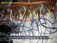
Another easy wiring question that escapes my
understanding or skill level.

I spent most of Friday evening attempting to solder
ground wires to the speedo and tach housings and also
solder ground wires to the small dash gauges so the
lights would light up. See Attached photo.

I sanded and steel wool cleaned the housings down to
white metal, wiped with xylol but again and again I
cannot get the copper wires and acid free solder to
stick to the metal housings. The solder melts very well
but then slides off no matter what I try.

If I scotchtape the ground wires in place; the lights
turn on when a battery current is applied. But that seems
pretty lame like a PO technique.

How does one solder all these ground wires to the dash
board gauges and lights?? A special type of solder is
required? What about if I squash the copper wire down
with a SS washer and then cover the washer with epoxy? Would that provide adequate grounding?

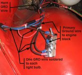
I have completed installation of the stainless steel
ground wire harness bars all over the car with one ground
wire per electrical connection as shown on the wiring
diagram. I am now only lacking the final ground wires for
the dash gauges. Then I think I will have 100% successfully
installed the grounding wire harness for a TR6.

Then it's onward to the color coded wires that I cannot
yet figure out. (confession time- I am bringing in a TR6
Dan Masters wire harness expert for the colored wires)

thanks as always,
 

Attachments

  • 253512-splices.jpg
    253512-splices.jpg
    139.9 KB · Views: 184

jerrybny

Jedi Knight
Offline
I don't believe they are supposed to be soldered. They should have a connector on them that goes on the posts that are used to hold them in place against the inner metal dashboard.
 

MrPandy

Senior Member
Offline
Can you use crimp-on ring connectors to attach the wire to each big gauge's mounting bracket? I have one on each of my big gauges from the original wiring harness, and there are no ground wires on the small gauges.
 

Geo Hahn

Yoda
Country flag
Offline
Quite right. Pick up a package of ring terminals for the gauge wire you're using (14 ga?). Make yourself a little harness to go from gauge to gauge to gauge to ground.

Easy way is to use a crimping tool to secure them -- better way is to yank off that plastic sleeve on the connector, crimp them then solder them and use a bit of shrink wrap over the connection.

Whatever else you do -- use black wire -- to avoid being a future DPO.
 

Geo Hahn

Yoda
Country flag
Offline
Hmmm... just looked at the photo. You don't need as many ground connections as you have drawn there. Simply grounding with a ring terminal under the thumbnuts on the speedo & tach will also provide a ground to the little lights (oil press?, hi beams, directional, etc) contained in those instruments.

Ignorant of TR6s I am... does the TR6 wood dash not have metal dash behind it (like the TR4)? Maybe 4's are that way just because they only offerred metal dashes in the early years.
 

MarkT

Senior Member
Offline
Dale,

As Geo Hahn notes above, I'm not sure that you need as many ground wires. I can't remember what year your car is ('71 rings a bell?), but looking at the "stock" wiring diagram in Dan's electrical book shows that only 4 of the gauge/dash lamps that are controlled through the rheostat are grounded through separate wires and 4 are not (I guess that these ground through the instrument.) This is assuming a '69-'72; after that the number of lamps increases, but still some are grounded by separate wires and some are not.

Without ripping out my dash, its hard to tell which ones ground through the instrument and which ones don't. I would assume (someone out there please correct me) that as the speedo and tach are bolted/secured to the metal dash panel behind the wooden dash these are the ones that ground through the instrument.

Hope this helps or at least reduces some of the confusion. I've still got all of this to look forward to....

Cheers,
Mark
 
OP
G

Guest

Guest
Guest
Offline
Dang, Dale, that setup looks like something Rube Goldberg might have dreamed up. What's with the grounding plate? Is that what comes with the uprated harness from Dan? The stock harness grounds to the steel dash backing plate. Do not solder to those gauges! You will be buying new ones. The posts ground to the metal dash plate via the flat bars held on with thumb screws. If this is what Dan offers with his new harness, I would suggest you drop him a line directly (if he hasn't already read this post). Since I am not familiar with his setup, some of the others have installed his harness in the TR6. Whenever there is a black wire, this is the ground (like on some of the light bulbs), at least in the stock harness. Check with Dan Masters.


Bill
 

dklawson

Yoda
Offline
Wow! That is something to behold.

As others have said, the common grounding method is to use ring terminals under the thumb screws used to secure the gauges to the dash. Where I've wanted multiple grounds like that, I've daisy-chained a single ground wire from gauge-to-gauge-to-gauge... and then off to ground. I use 16 AWG wire which will be sufficient for the lamps and electric tachs.

The only gauge I've really seen benefit from a soldered-on terminal directly to its case are the old pre- voltage stabilizer fuel gauges. If you loose the ground on those gauges the instrument really acts up. A little corrosion on their mounting screws is all it takes to have problems.

For future reference, if you want to solder to steel, you need to clean and prep the surface as you did but follow up with acid flux or acid core solder. Obviously after that you need to neutralize and clean the area (sudsy ammonia is good for that). Acid flux is almost impossible to find these days. (Perhaps OSHA... who knows why). If you can't find that, you can use soldering iron tinning compound (works sometimes) or a little phosphoric acid. Melt the solder on your iron first, then wash off the flux, then apply to the acid on the metal. In the old days you could/would dissolve zinc in hydrochloric (muriatic) acid until it was saturated with zinc. The resulting zinc chloride was your homemade flux. I'm not sure where you'd get the zinc today.
 

Keoke

Great Pumpkin
Country flag
Offline
Yes soldering to steel can be accomplished as you stated DK. However, when working with electrical copper wiring components only rosin cored solder should be used.--Fwiw---Keoke- /ubbthreads/images/graemlins/yesnod.gif
 
OP
T

Tinster

Guest
Guest
Offline
Thanks all!! I now have the gauge ground wires connected
with nuts and screws. All the lights function except
for the tach. When I started this project no light on
the auto lit up. I can live without tach lights.

Bill: after twice installing and ripping out new wires
in the rear end and nothing functioning properly, I found
the grounding bar concept for TR6 autos somewhere on the
web.

Every electrical device, bulb or gizzmo on my 69TR now
is connected, one to one, to a stainless steel grounding
bar. The grounding bars are all solidly attached to bare
metal and then I installed wires going from the grounding
plate to the engine or something metal connected to the engine. Everything seems to light up when I attach a 12v battery.

Here is a photo of the grounding bar for the driver's side, front lights, horn, markers, etc.

regards,

dale
 

Attachments

  • 253883-grind4.jpg
    253883-grind4.jpg
    55.4 KB · Views: 112
OP
G

Guest

Guest
Guest
Offline
Dale, forever the PITA, why stainless as a grounding bar? Methinks there are other metals that conduct electicity better, such as carbon steel, aluminum, copper,...I don't think that stainless is that high up the ladder.

Always a proponent of the KISS rule.


Bill
 

piman

Darth Vader
Offline
Hello Dale,

what I have done before is to clean the steel on a chassis earth point and then tin that directly with 60\40 electrical solder, then simply bolt up the ring crimped cables.

A point about soldering to flexible automotive cables, unless the cable is also mechanical crimped away from the lug to support the cable, the solder forms a stress point between the flexible unsoldered section and the lug and is likely to break off due to vibration.
My preference is a lug crimped with a ratchet style crimper.

Alec
 

dklawson

Yoda
Offline
Keoke, we've had this discussion before. When you're soldering to steel you have to use acid flux, then you neutralize and wash it away. There is no substitute if you need to solder to steel.

BTW, I don't solder wires directly to gauges, I solder a male spade lug for such purposes... not a crimp terminal as such but a male spade bent into an "L" profile.

Dale, the stainless won't corrode, but as TR6Bill said there are much better conductors. Regardless, it sounds like you've made great progress and will have trouble-free connections for the forseable future.
 
OP
T

Tinster

Guest
Guest
Offline
THANKS FOR THE TIPS!!

I am using stainless because I live about 2 miles inland
from the ocean. Most of the small nuts, bolts and screws
that came with my TR6 purchase were badly rusted and looked
like K-Mart 50 for $buck specials. (Remember the PO of my
car did not change the oil during the 4 years he owned the car)

I am installing new SS wherever strength is not required.
I purchase at a local nuts and bolts speciality store
and if I am in doubt, I ask the experts.

I may have a dead as dirt crypt car for now but one
day......................
...........................yahoooooo!!!!!!!!

dale
 

Camping57

Senior Member
Offline
One thing to think about with using the stailess grounding bar is that the bar itself will not corrode, but you are setting up a heck of a galvanic cell. The brass in the terminals is pretty far from passive stainless and solder is even further away. What is going to happen is that over time the brass terminals and any solder that is in them will be eaten away (they are more anodic than SS). You would do better to use a brass grounding bar. It resists corrosion well, matches up in galvanic response and conducts much better than SS.
 
OP
T

Tinster

Guest
Guest
Offline
Thanks Camp!

It took me almost 2 months of searching to
find the stainless bars here on the island.
I found them in a pharmaceutical metal shop.

Where would I begin my search to locate brass
grounding bars? What type of place would stock
.090 brass that could be cut into 1" wide bars?

Would I also need to switch out the stainless nuts
and bolts for brass ones?

BTW- what is a galvanic cell? I never heard of that one.

thanks,
Tinster
 

Camping57

Senior Member
Offline
You can get brass (along with almost anything else) from McMaster Carr (https://www.mcmaster.com/). Otherwise a local hobby shop is likely to have brass strip because it is used a lot in RC planes and other models. You may also be able to find brass stock at a boating supply store becasue it is used a lot for brightwork on boats.

A galvanic cell is set up any time that you have different metals in contact with one another in the presence of an aqueous solution (salt water is the best media). It actually creates a miniature battery with the water acting as the conductor with ions flowing from one metal to the other. One metal will corrode (the anode) and the other one won't. An example of how this is used to an advantage is the use of magnesium protective anode on the lower units of some boat motors. Over time the magnesium is eaten away and the aluminum lower unit is spared from corrosion.
We get involved in assembling a lot of different products in my business and galvanic corrosion is one of the biggest issues that shows up in automotive applications.
Here is a link to a better explaination of galvanic cells:
https://www.eaa1000.av.org/technicl/corrosion/galvanic.htm

Yes you would want to switch out the fasteners to brass. You want to have all of the components that are in contact as close as possible on the galvanic chart.
 
OP
T

Tinster

Guest
Guest
Offline
Awesome Camp!!

I did have a anode on my boat, now that I think
about it.

tin
 

brdave

Senior Member
Offline
Just curious, but why not connect the various grounds to one bolt attached directly to the body of the car?
dave
 
OP
G

Guest

Guest
Guest
Offline
Dang, Dave, what are you trying to do, make things easy?

Actually, in the number of circuits that I have added to my car that are not run through the stock harness and are totally independant of it, that is all that I did. Ran them to convenient and neat locations for grounds. Always used a ring-ended grounding tap that I crimped, soldered and covered with shrink tubing (for neatness). Worked for me.

Bill
 
Similar threads
Thread starter Title Forum Replies Date
Atrus DIY Temp gauge repair - Solder issues Spridgets 40
S TR2/3/3A re- solder my dash lights Triumph 6
KVH General Tech Solder Skills Triumph 14
B Leaded solder vs non leaded solder Triumph 8
KiKi Eastwood Body Solder Restoration & Tools 5
ncbugeye To solder or not to solder, and where... Spridgets 23
J For Sale Gauge brackets (lot of 7) for sale Other British Classifieds 0
Rick_Thompson TR2/3/3A Overheat issue, gauge adjustment Triumph 9
G MGB ugh.....the fuel gauge went to *** again! MG 8
RJS TR4/4A Smiths Oil Temp Gauge Triumph 11
J MGB Oil Pressure Gauge Gives Constant Reading -- Doesn't Seem Right MG 15
roscoe Fuel Gauge Austin Healey 0
G Smith's temp gauge repair Restoration & Tools 4
CARSINC eBay Gauge Packages Spridgets 6
Gliderman8 TR6 Excessive reading on volt gauge Triumph 17
K TR2/3/3A Wiring a voltmeter gauge to replace the ammeter. Triumph 1
Gatheringtree TR2/3/3A Gauge Set Triumph 17
jfarris For Sale TR4 Fuel Gauge with 2 Transmitters Triumph Classifieds 0
D Fuel Gauge Austin Healey 7
BoyRacer Thread Pitch Gauge from "British Tool and Fasteners" Austin Healey 0
LD-Ordie TR2/3/3A TR3 gauge service Triumph 11
RJS General TR Oil Pressure Gauge - Test Triumph 11
RJS TR4/4A R&R Oil Pressure Gauge Triumph 7
RJS TR4/4A TR4A Temp Gauge Scale Triumph 6
B For Sale BaulyCars - Gauge Bezels Triumph Classifieds 0
AngliaGT MGB-GT Gauge Repair Recommendations? MG 4
BierRunner TR6 Temperature Gauge Triumph 8
T Wanted Working Fuel Gauge for TR3A Triumph Classifieds 5
HighAltitudeTR3 T-Series MGTD Sheet Metal Gauge?? MG 0
Lairhead52 Wanted Oil Press Gauge Triumph Classifieds 0
T TR2/3/3A TR3A Fuel Gauge problem Triumph 10
B TR4/4A Jaeger Gauge Question Triumph 16
K TR2/3/3A TR3 with alternator conversion... red light stays on and low voltage on the voltmeter gauge? Triumph 1
Retired2020 TR5/TR250 TR250 smith gauge Triumph 7
L Oil Pressure Gauge Austin Healey 5
Martinld123 Problems with my BN2 Temp Gauge reading Austin Healey 13
B Fluctuating Fuel Gauge 1960 Bugeye Spridgets 4
R TR2/3/3A Amp Gauge-erratic reading after alternator conversion Triumph 39
Fanch00 Inoperative Fuel Gauge Austin Healey 10
R Coolant temperature gauge Spridgets 8
EWD TR6 Temp Gauge - 74 TR6 Triumph 11
Boink Early Mini Fuel Gauge - adjusting it British Motor Corp 0
Editor_Reid Water Temp Gauge Austin Healey 5
J TR6 73 TR6 Temp Gauge Wiring Question Triumph 6
Gliderman8 TR6 Vacuum Gauge Hookup Triumph 11
E Gauge Lights Austin Healey 4
S WANTED: Healey BN1 "Smiths" Fuel Gauge (Dead or Alive) Austin Healey Classifieds 3
K TR2/3/3A Using a dial gauge to adjust valves when rocker arm surfaces are worn? Triumph 9
R TR2/3/3A Fuel Gauge Triumph 19
nichola TR6 Smiths volt gauge needle barely moves Triumph 25

Similar threads

Top