• Hey there Guest!
    If you enjoy BCF and find our forum a useful resource, if you appreciate not having ads pop up all over the place and you want to ensure we can stay online - Please consider supporting with an "optional" low-cost annual subscription.
    **Upgrade Now**
    (PS: Subscribers don't see this UGLY banner)
Tips
Tips

TR2/3/3A Brake MC Bracket and pedal assembly install

PatGalvin

Jedi Warrior
Country flag
Offline
Hi Guys

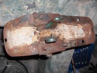
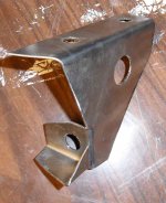
Time to reinstall some new parts (ok, newly cleaned and painted parts).

Brake MC Bracket goes on top. Then we have body sheet metal. The pedal assembly hangs beneath the body, in the drivers compartment. So, how do I bolt this together? Do I run bolts down through the bracket and sheet metal and then through pedal assembly, installing nuts under the pedal assembly? Or do bolts start at pedal assembly and run upward, with nuts on the MC bracket. See attached photo of my bracket. After this is installed, I can hang my MC's on the bracket, attach pedals to MC forks, and then start my hydraulic plumbing. Anything wrong with this sequence?

Completed photos to follow.

Thanks

Pat


TexasKnucklehead

Jedi Knight
Country flag
Offline
Pat,
There is an assembly that holds the clutch and brake pedals. Part of that assembly, is bolts that extend upwards to hold the M/C bracket. It's a sandwich with nuts on top.
This picture of that assembly also shows the brake light switch I made, so I didnt have to use a hydrolic switch.
 
OP
PatGalvin

PatGalvin

Jedi Warrior
Country flag
Offline
Thanks Jer.
Let me go home and check this out. Maybe I'm imagining things...
I like your brake switch bracket. Well done! What diameter hole for brake switch and where did you buy it (might have to copy your good work.)

Pat
 

TexasKnucklehead

Jedi Knight
Country flag
Offline
Funny thing about the switch. I had one lying around from who knows where, and it seemed to work, but one of my new M/Cs leaked, and I'm using DOT5 silicon fluid. Apparently a drip got onto the brake switch. It didn't work long after that. OReileys looked up a replacement, but I had to drill the hole a little larger and get metric lock nuts for it. It's been working fine since. I think the switch is from a Nisson or something... BWD S686 IDI 18-1980 stop lite switch and nuts (it took a day or two to show up).

If you go that route, remember you'll need another (green) hot wire to the switch, and then some way to connect it to the brake lights -I ran a G/P wire across the floor (inside H/S tubing) to the back rather than cut the harness and tap into it. Plus my harness was actually for an older model with a single brake light and the switch on the driver side, so these mods were 'required' anyway. I cut off the piece of wire that extends from the harness for the hydrolic switch. It's these kind of mods that are hard to detect, but may someday make it hard to work on.
 

Jerry

Darth Vader
Gold
Country flag
Offline
I think once you see the pieces you can tell how it goes together. I wake up at night wondering how stuff goes together, and then find out it is really not that complicated.
Jerry
 
OP
PatGalvin

PatGalvin

Jedi Warrior
Country flag
Offline
So my TS38096 does not have studs like Jerry's. See below. But, it appears that bolts go up from underneath, and finished with nuts inside the MC bracket. Thanks for responses and good idea on the brake switch. Yes, pretty ugly parts. they cleaned up quite nicely as you'll see soon.

Pat

 
Last edited:

TexasKnucklehead

Jedi Knight
Country flag
Offline
Pat,

They are not studs, they are bolts that have been welded on the bottom side. Other than an assembly issue, I can't see why you couldn't use bolts that are not welded.
 
OP
PatGalvin

PatGalvin

Jedi Warrior
Country flag
Offline
Has anyone had any problem with brake or clutch pedal binding a bit? I put it all back together with a healthy dose of bearing grease. The brake pedal is binding a little and, with spring installed, won't return the last inch or so of travel, on its own accord. Before I get the MC's mounted, do I need to deal with this or is it not a big deal? It might loosen up on it's own, with repeated use. This was a PITA to install, so I'm not terribly enthused with removing it and trying to diagnose the binding. But I will, if necessary. Thoughts?

And Jer, having those bolts tacked on would have helped a lot! It takes very long arms to install this.

Oh, and another thing. In case you're wondering what that little cutout window in the body sheet metal is for, behind the master cylinders.... It's for installing the MC's, I'm sure. Without it, it's near impossible to get a wrench down there and bolt the MC's to the bracket. Unless I'm missing something.

Pat


mallard

Luke Skywalker
Country flag
Offline
Pat nice looking installation, but I would make sure you correct the binding before going any further. I made my own new bushings for the pedals and they don't bind at all. You don't want to have it all installed including brake fluid and find that it still binds. I put a small bead of seam sealer under the pedal assembly to keep out any water, and also some on that cutout that you mentioned.
 

luke44

Jedi Warrior
Silver
Country flag
Offline
Has anyone had any problem with brake or clutch pedal binding a bit? I put it all back together with a healthy dose of bearing grease. The brake pedal is binding a little and, with spring installed, won't return the last inch or so of travel, on its own accord. .... Thoughts?

I had the exact same problem. It just required a lot of polishing of the pin with a wire wheel... take a look here at posts #38-40 ...especially the second picture.
 

CJD

Yoda
Country flag
Offline
Beautiful Pat! I'd get it so the spring returns the pedal before you mount it. Just a lot easier to deal with before you install and have to work in close quarters.
 

TexasKnucklehead

Jedi Knight
Country flag
Offline
Pat, I agree, the spring should easily return the pedals. When I had the assembly in hand, I could move the end up/down and the pedals would remain verticle. They should move very freely on the shaft once it's all cleaned and polished. -I know mine were stuck to the shaft long before I took it apart, but that's not the point. You need to remember that if you add a brake light switch, it has a spring inside it, that will also offer resistance to the brake pedal returning the whole way. I doubt you want your brake light sticking on because the pedal didn't return. Also the new M/C seals will drag a little (especially when new) and offer resistance to the pedal returning. At first, I had to add a second spring to return the brake pedal, but after a few thousand presses, it has been removed and the pedal is returning fine with only the original spring.

As far as sealing it, I sealed the little back plate. It is difficult removing the M/Cs, but easier than the top nut on the starter. Getting it all water tight is not possible. The end of the pedals has slots cut (for travel) where the push rod attaches. Water/dust can always enter through that slot -which is large compared to the sheet metal gaps. The "cover" on the under side (that holds the pedal shaft) has no drain hole so I added one to mine. You can see where mine got a little sand in there during Katrina and neither pedal would move after the sand dried a little.
 

Attachments

  • pedalling_dirt.jpg
    pedalling_dirt.jpg
    198.7 KB · Views: 54
OP
PatGalvin

PatGalvin

Jedi Warrior
Country flag
Offline
I had serious rust and pitting on all the pedal assembly sheet metal but the polished shaft and bushings were clean and tight. Brightened it up with a little 1,000 grit sandpaper and it operated really smooth. Two things.

1) Putting the pedal assembly back together was like a puzzle. I finally punted and used the die grinder to grind the lower housing so I could slide the pedal assembly into the large bracket and fit the top brackets.

2) After blasting, I epoxy primed and painted all the parts. That created a slightly thicker sheet metal surface for the lower housing and the top brackets. With paint in the pedal shaft slot and on these sheet metal surfaces, there was just not enough room to fit it all back together. I know, hard to believe clearances were that tight. So, I scuffed off the paint on the large lower housing and on the top brackets where they fit in the slot. That helped a lot, but the brake side is still tight.

So, I'll pull it all apart and remove the paint from within the pedal shaft slot too. I hope that will do the trick.

Lesson's learned:

1) Don't paint the pedal shaft slots at all. Bearing grease should prevent rust, in the future. And, if you paint the lower housing and brackets, plan on scuffing the areas where these fit together to ensure adequate clearance for the whole thing to rotate.

2) This is way easier if you have the bolts tack welded to the lower housing (like Jerry the Knucklehead's pic). Or, if you have Gumby-like arms like the guy from the Fantastic Four, it should be a breeze.

Oh, third lesson. Don't seam seal that little sheet metal window until you install your MCs and verify the are leak tight and working. I painted and sealed it and now get to go back with a flat razor and peel it apart so as to access MC bolts. If it's worth doing, it's worth doing twice, I suppose...

Pat
 
Last edited:

TexasKnucklehead

Jedi Knight
Country flag
Offline
Just to be clear... that shaft should also fall out of the pedal in your last picture...

I remember having a little trouble with the metal "rings" aside the pedal, fitting into the "cover" without rubbing too much.

It is a puzzle. Someimes pictures are not enough to get it back together.
 
OP
PatGalvin

PatGalvin

Jedi Warrior
Country flag
Offline
Wow, I though mine looked bad. You have a beach inside that housing.
I'm going to take it apart and try and free it up as per my last post.
Then, if I have to double spring it, I can do that too. I'm sure the double spring would pull it back to position. It takes a light touch to move it back now.

Jer, for your electric brake switch, did you weld a little flat plate on the pedal assembly for switch end to ride on, or just ensure the bracket was positioned so the switch is perfectly centered on the pedal edge?

Thanks for the tips. Drain hole is a good idea. Hope I never have to hose out my engine compartment but I see how collecting water would be easy, due to top of pedal assembly being open.
 
OP
PatGalvin

PatGalvin

Jedi Warrior
Country flag
Offline
Just to be clear... that shaft should also fall out of the pedal in your last picture...

I remember having a little trouble with the metal "rings" aside the pedal, fitting into the "cover" without rubbing too much.

It is a puzzle. Sometimes pictures are not enough to get it back together.

Hold on. You mean the polished shaft needs to be removed from the brake pedal? In the photo I just posted, the shaft is installed in that pedal. If it is in there tight (which it is), do I need to make sure it is removed, for the pedal assembly to operate properly? I may have to rig up the vice as a press to get that one out. Please let me know. And thanks for the info.
 

CJD

Yoda
Country flag
Offline
Hold on. You mean the polished shaft needs to be removed from the brake pedal? In the photo I just posted, the shaft is installed in that pedal. If it is in there tight (which it is), do I need to make sure it is removed, for the pedal assembly to operate properly? I may have to rig up the vice as a press to get that one out. Please let me know. And thanks for the info.

Yep, that's what he means! That shaft is separate and the pedals should both rotate on it.
 

TexasKnucklehead

Jedi Knight
Country flag
Offline
Well, I'm sure my brake pedal was stuck onto the shaft long before Katrina filled the housing with sand -and it probably worked that way... but, if you are in there anyway, the shaft can/should be removed, and then the brake pedal will rotate much easier because the shaft is free to rotate at will on each pedal. It pressed right out in a vice, but took some persuading.

I did not weld anything, but bent some scrap sheet metal to be sure the brake light switch would always be aligned properly on the center on the brake pedal. There are 4 holes drilled, 2 for the mounting at the top, 1 for the switch and 1 for clearance of the shaft end bolt. There are other ways to accomplish it, but I wanted something that looked as if it belonged there. the down side is that it must be installed when the "cover" is installed.


John is a faster typist...
 

Attachments

  • brake_bracket1.jpg
    brake_bracket1.jpg
    119.8 KB · Views: 56
Last edited:

CJD

Yoda
Country flag
Offline
If my memory serves, once you tighten the bolts that go through the pedal box and into the pin, then the pin is held stationary. In other words, all pedal motion is around the pin, so the pedals must be loose and lubricated on the pin. If your pin is fixed inside the brake pedal, then you were using the side bolts and pedal box edge as the bearing, so you could never fully tighten the bolts without locking the brake pedal.

Maybe faster, but not as well thought out...
 
Similar threads
Thread starter Title Forum Replies Date
S BN1 clutch and brake pedal bracket Austin Healey 3
vette Brake Bracket Austin Healey 5
M TR6 Front Brake Caliper Bracket Part Identification Triumph 0
PatGalvin TR2/3/3A Brake Master Cylinder Fluid Reservoir Bracket needed, TR3A Triumph 6
J TR2/3/3A TR3 Lockheed brake/clutch MC bracket... Triumph 11
Steve_S Odd Brake Bracket - Identify? Racing 5
6 Brake Fluid Spridgets 4
F Excessive Brake Pedal Travel Austin Healey 3
F Disc Brake Shimming Austin Healey 8
PDIGIO_6x3 TR6 BRAKE TUBING KITS Triumph 6
L Red Rubber Brake Grease Austin Healey 2
Martinld123 Emergency Brake Doesn't Release Austin Healey 9
71TR6 TR2/3/3A Aftermarket brake and clutch master cylinders - black extension? Triumph 6
petnatcar Aluminum Brake Fluid Reservior Austin Healey 5
M Brake Servo Austin Healey 2
E TR4/4A What Flare to put on a TR4 Brake Line Triumph 2
scottkilpatrick TR4/4A TR4 Rear Brake Drum Removal - Basic Question Triumph 16
T Spin-On Oil Filters for Cars with a Brake Servo Austin Healey 3
J MGB BRAKE VALVE ? MG 11
G Brake Light Switch Failure Austin Healey 24
B Rear Brake Cylinders Austin Healey 4
K TR2/3/3A Brand new brake caliper question... Triumph 8
K TR2/3/3A Front brake hub removal to access Vertical Link bolts(screws) Attached pictures. Triumph 1
K TR2/3/3A How to remove the front brake hub from the brake disc? Triumph 11
J TR2/3/3A Brake Line Flares Triumph 8
Frameman 1949 Brake Bleeding Austin Healey 0
Racer-X- Frame mounted power brake pedal/booster/master cylinder kits for RHD cars? Restoration & Tools 1
Chrisc9 TR6 TR6 brake light Triumph 6
L T-Series Another brake prob. ? MG 12
S TR2/3/3A brass fitting from a steel brake line Triumph 2
Sopwith_Camel MGB pulsing brake pedal MG 10
Got_All_4 TR6 Triumph TR6 PDWA Brake Question Triumph 1
bighealeysource Front Brake Adjusters Austin Healey 0
SherpaPilot TR6 Brake Fluid in Servo? Triumph 0
TAS525 TR2/3/3A Thoughts on Brake Pads Triumph 12
Gundog61 BN2 Brake Drums Austin Healey 5
KVH General TR Rear Brake Shoe Orientation Triumph 12
R TR6 Help: Brake Part Source or …. ? Triumph 1
mezy vauxhll brake pipes Other British Cars 0
KVH General Tech TR4A Brake Bleeding Triumph 5
R Brake Adjustment Spridgets 2
Walter74 Brake Servo Location Austin Healey 6
A 100-6 Brake Lights Austin Healey 2
prb51 100-6 Brake Master Cylinder Bore Austin Healey 5
prb51 Girling Brake Fluid Reservoir Cap Austin Healey 6
KVH General Tech Brake Fluid Triumph 5
Lin Brake/Clutch Fluid Austin Healey 11
AUSMHLY Castrol DOT4 Brake Fluid Austin Healey 6
bighealeysource Brake Master Cylinder Austin Healey 27
S TR2/3/3A Lockheed brake system Triumph 7

Similar threads

Top