Hey Guest!


 but were afraid to ask:
  STOP!! Never post your email address in open forums. Bots can "harvest" your email! If you must share your email use a Private Message or use the
  smilie in place of the real @
 Pretty Please - add it to our Events forum(s) and add to the calendar! >>
OP
GBRandy
Jedi Knight
Offline
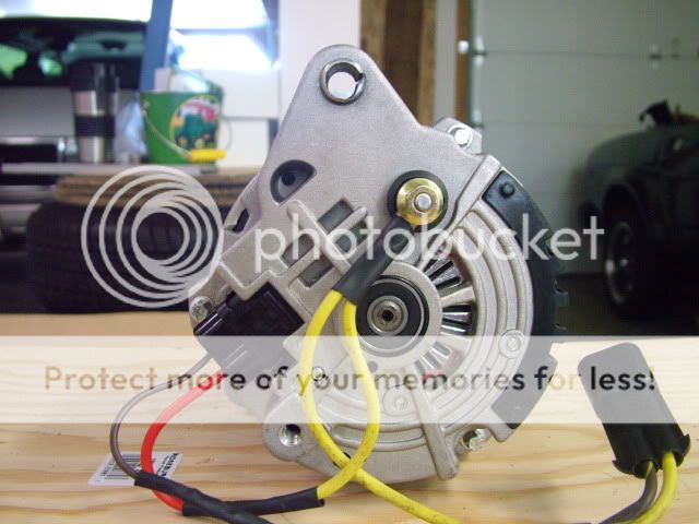
Here is the back side of the 8215 before installation:

The wire harness and the ident for the wiring.
S (red) => Brown sense wire
F (brown)=> Not used
L (brown)=> Brown / yellow dash light wire
P (gray) => Not used

8215 Alternator installed (ignore my wire harness colors I did a rebuild many years ago and did not have the right colors to work with. I need to change that, but that's a project for a cold fall afternoon):

The only real physical differences were:
1. you need swap the serpentine pully for a 2.5" - 2.7" v belt one.
2. You need to move the back plate to re-align the mounting holes (reclocking).
3. The adjustment bracket attach point is not threaded (need through bolt and nut instead)
4. The reach on the hole pattern is different.
The stock A133 alternator I took out was 6.25" across. The 8215 was 5.5". It did not matter. Same brackets & belt on the install.

The final check I did was 14.2 volts no load. 13.4 volts with lights, front & rear fogs & radio on as well as the fans on high. That was at idle
105 amps at the battery cable in the back by the battery.
Everything runs as it should without dimming or slowing.
It is early, but it sure seems to make the car run smoother.
Given that this idea was lifted from a TR7 and that car had a 35 amp alternator, this would be one heck of an upgrade! Even with my A133 alternator it is vast improvement and should fit in any wedge car.
TR7 (all) = 17 ACR - 35 amp
TR8 Carb / no AC = 20 ACR - ___amp
TR8 Carb / AC = 25 ACR - 65 Amp
TR8 FI / AC = A133 - 75 amp
Thanks for the all the help folks..... This seems like a worth while $115 alternator option... My A133 is at the shop being rebuilt.
The wire harness and the ident for the wiring.
S (red) => Brown sense wire
F (brown)=> Not used
L (brown)=> Brown / yellow dash light wire
P (gray) => Not used
8215 Alternator installed (ignore my wire harness colors I did a rebuild many years ago and did not have the right colors to work with. I need to change that, but that's a project for a cold fall afternoon):
The only real physical differences were:
1. you need swap the serpentine pully for a 2.5" - 2.7" v belt one.
2. You need to move the back plate to re-align the mounting holes (reclocking).
3. The adjustment bracket attach point is not threaded (need through bolt and nut instead)
4. The reach on the hole pattern is different.
The stock A133 alternator I took out was 6.25" across. The 8215 was 5.5". It did not matter. Same brackets & belt on the install.
The final check I did was 14.2 volts no load. 13.4 volts with lights, front & rear fogs & radio on as well as the fans on high. That was at idle
105 amps at the battery cable in the back by the battery.
Everything runs as it should without dimming or slowing.
It is early, but it sure seems to make the car run smoother.
Given that this idea was lifted from a TR7 and that car had a 35 amp alternator, this would be one heck of an upgrade! Even with my A133 alternator it is vast improvement and should fit in any wedge car.
TR7 (all) = 17 ACR - 35 amp
TR8 Carb / no AC = 20 ACR - ___amp
TR8 Carb / AC = 25 ACR - 65 Amp
TR8 FI / AC = A133 - 75 amp
Thanks for the all the help folks..... This seems like a worth while $115 alternator option... My A133 is at the shop being rebuilt.