• Hi Guest!
    You can help ensure that British Car Forum (BCF) continues to provide a great place to engage in the British car hobby! If you find BCF a beneficial community, please consider supporting our efforts with a subscription.

    There are some perks with a member upgrade!
    **Upgrade Now**
    (PS: Subscribers don't see this gawd-aweful banner
Tips
Tips

TR2/3/3A Rear tail light cutouts

99 of the little suckers!

IMG_1236.jpg

Which means there must be 396 of these.

IMG_1237.jpg

Still need to make a few double length cage nuts but will do them by hand. Shears are still going strong although I might want to sharpen the cutter before I start on my next car. Happy to pull it apart now and put it away in the box of tools that may be used again some day.

Next job is find some 1/2" by 3/16" steel bar to make the nuts. Was able to recover 15 from the old panels so still a few short of the 99 needed in total.
 

Attachments

  • IMG_1235.jpg
    IMG_1235.jpg
    74.7 KB · Views: 82
Haven't found any steel to make the nuts yet. It seems the steel suppliers in Perth don't see a market for steel flat bar less than 1" in width!
decided to have a go at one of the front inner fenders. The usual rust along the edge where the outer fender bolts on but also bad pitting in the front and top. Likewise the rear top and the lower edge where it attaches to the chassis.
Started by replacing the lower edge as it was all flat sections and straight bends. Took out the inner front flat section and body mount and replaced it. Then took a pattern off the lower front section that includes the recess for the front indicator.

IMG_1245.jpg
This section was done on a wood stump with a depression in it to shrink the inner curve and then the English wheel to bring up the curve in the front and smooth the hammer marks. The depression for the indicator light was done on the sand bag and then finished on the end of a piece of 3" pipe. Lower flange was turned up on my home made bead roller using a tipping wheel.
IMG_1247.jpg


IMG_1248.jpg

Needed to replace rusted section above and below the headlight depression as well as some of the depression itself so decided to replace the whole lot. Again, the inner curve was shrunk with a blocking hammer on a wood stump and smoothed on the wheel. The depression for the headlight shell is left until the section is fully tigged into the fender so I didn't have to work too close to the edge of the piece of metal.
IMG_1250.jpg
IMG_1251.jpg

IMG_1252.jpg

At this stage the headlight depression has to be hammered in which has been done but no photo yet.

Still got to drill necessary holes and attach cage nuts etc.
 
Decided to have a go at the rear mudguards. I saw on Charles' email from TRF that new rear mudguards on special are about $900 each. Way outside my budget. Actually I don't have a budget!

The two rear mudguards are rusted thin although they retain the correct shape so they will make good models to work from.

I took a template from the two so that it averaged the differences between the two guards. Just used newspaper to make the templates. Also decided to make the guards in two halves and will then tig them together as a full guard is too big for me to work in the English Wheel.

IMG_1271.jpg
Transferred the pattern to sheet and cut the blanks out with a jig saw
IMG_1272.jpg
Left the metal in the curve to give the sheet strength For when I shrink the outer edge on the wooden block with a hammer.
IMG_1273.jpg
Did the rear half first. Started by rolling the top and rear edges over a sectin of pipe. Then shrunk the tail light section on the block with a hammer and then tighten up the area on the shrinker. After this shot was taken, I used the hammer and sand bag to give more body to the panel and smothed it on the English Wheel.
IMG_1277.jpg
Finished the main shape although still got to do planishing and surface finishing ...
IMG_1278.jpg
And cut in slots for bolts. The flanges were turned over on my home made bead roller and then finished with hammer and dolly.
IMG_1279.jpg

Next I will have a go at the front half and then tig the two together.
Lionel
 
Very nice work! The rear area actually has a very slight convex shape to keep it from oil-canning. I can't tell if you worked that into it yet or not.

You've got me planning my next shop...I'm going to have to expand my sheet metal tools!
 
Hi John. The panel is curved. Worked that in with the wheel. Put the shape into the panel before rolling the flanges and then stretched / shrunk the flanges to fine tune the shape. The top edge of the rear is slightly dipped as it approaches the tail light mounting. A little bit of hammer and dolly work to start the dip and then spread the curve evenly along the top edge by stretching the rear top flange.

I have found using the bead roller gives a nice clean bend on the flange also.
 
Check your pm's there is an offer from a tr enthusiast in Perth who has a cnc laser, press brake and guillotine. All you need is material if we dont have something in stock.
 
I believe I read earlier in this thread that you were not trained in sheet metal work. You are demonstrating some very fancy work with the hammer, English wheel etc.
I fought one of my rear wings for days trying to undo a previous accident repair. An English wheel may have helped. I was a little wary of trying to heat shrink as I had had less than spectacular results on the front wing. Most of the front wing problems traced back to the inner sill being set 1/8"+ too low and put tension on the wing.

Great work. Keep it up and bring us along so we can watch and learn.

David
 
Thanks for your comment David. I spend a lot of time thinking about the best way to tackle a job before starting and then dive right in. Often find I have to rethink my approach halway through the job. As they say, "a plan is always a work in progress".

I only started using the wheel and shrinker stretcher about one and a half years ago. Got the TIG at the same time so it has been a continuous learning period. Never used any of them before that. Spent lots of time watching guys like Lazze, Jodie on Welding Tips and Tricks and a whole stack of other amazing guys who put out their skills for amateurs like me to learn. Then it has been a matter of give it a go! Still got a long way to go, but I find trying to take it slowly and not rush things helps. If in doubt I stop and think around the issue for a while. Made a few stuff ups but as Edison of light bulb fame said, I now know several more ways not to do it.

Re your front wing, my car is totally disassembled so putting it back together will be lots of trial and error. I think John made the comment once, only tack weld things until you are sure they are right. Going to be a lot of tack welds on this car!
 
I found self tappers better than spot welds,easy to take out and reposition.
Good old Aussi know how,have a go you mug,keep up the good work Lionel.
Graham
 
John I thought about aluminium but had some left over steel sheet plus I had been working on my tig welding of steel so went down the traditional pathway. Not like I am going to be racing the car either as just getting it together will be an accomplishment.
Thanks for the support Graham and also for the opportunity to check out your car the other day. A top notch job.

Continued with the front part of the mudguard. Actually considered stopping and starting again this morning as I was having a lot of trouble shrinking the outer circumference of the panel. In retrospect it would have been easier to do the outer part separately to the inner and weld the two together. I did this with the rear inner wheel arches as they were too deep for me to shrink them to shape. I try not to stretch too much and thin the metal. Prefer to increase the thickness by shrinking.

Anyway I persevered and then it started to come together. I ended up cheating and resorting to using the shrinker to get the last rough profile to shape. Also decided to make myself a tuck fork to get some shrinking deep in the panel. Together, they did the job.

IMG_1273.jpg
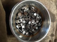
The following photo shows the mangled piece of metal after hammering on the block to shrink the outer edge. At this stage I was having difficulty getting the shrink deep enough into the panel and so I took time of to make a tuck shrinking fork which is shown in a later photo. This allowed me to reach in further from the edge of the panel and start my shrinks deeper in. At this stage, it always looks really ugly. Sometimes I roll it on the wheel just to make it look better and I feel that it is progressing
IMG_1283.jpg
By the following photo I had spent quite some time using the sandbag to create the main shape and the wheel to raise some areas and also smooth it. To get the metal to fit the pattern, I had to resort to the shrinker to tighten the profile.
IMG_1284.jpg
I used the bead roller to break the flanges and then hammer and dolly to complete the bend and tighten the radius of the bend. When the flange is bent over there is either too much metal or too little metal depending on whether it is on an inner or outer curve. This totally stuffs the lovely profile that previously existed. The shrinker stretcher is used on the flanges to get the correct curve back into the outer and inner radii of the panel. So at this stage it is a necessary to present it to the car body to get the correct outer radius and line along the body panel. Also it has to be compared with profiles to get the correct curve back in the body of the panel.
IMG_1285.jpg
It turned out OK. You can see in the following photo the tuck fork I made to get deeper shrinks on the panel.
IMG_1287.jpg
Rather than spend a lot of time building a full buck to make the panel, I made a paper pattern and then supplemented it with a number of profiles I copied from the panel. These profiles match what the professionals refer to as stations on the buck. I marked the panel and the sheet I was forming and used the profiles to determine how I raised or lowered the metal at several locations. You may be able to see on the above photo lines where each profile relates to the panel. They can be seen on the old fender as well.
IMG_1288.jpg

Now to join the two halves together. You can see that I deliberately split the two halves at the thinnest section of the fender. My welding is not my strong point so I try to minimise the length of my welds. Another reason I wanted to do the guard in two pieces rather than three.
 
Took some time out to check to see if the two critical parts I have been making actually fitted together. Both parts straight from the templates matched up very well. I was really chuffed.

IMG_1289.jpg

IMG_1290.jpg

Fitted the two fender halves to the rear tub to determine an accurate line to tig them together.

IMG_1292.jpg

Removed them, cut along the line, refitted to true the line up and then tigged the join.

IMG_1293.jpg

Very happy with the way it worked out.
 
Very impressive work.

Can you post a photo of the shrinker and stretcher you are using. I have the harbor freight ones that just grip yjr edge of the panel and either pull or push the metal.

David
 
David the shrinker stretcher I have is the same basic type as yours. I think there were two options when I bought it and I opted for the one with the deeper throat to reach into the panel for a deeper shrink. I only have one device with two sets of jaws so I have to swap jaws when I switch from shrinking to stretching. A bit of a pain but I don't have that much to do so I live with it. Would be nice to have two devices. The only issue I have with it is the corners of the jaws are sharp so some time I will grind them off slightly. The other option had rounded jaws but the throat wasn't deep enough for my liking.

As with all these shrinkers, they marr the surface of the metal when they grip but for the price you pay, they do a great job. I have an air planishing hammer and would like to have a go at making a pair of thumbnail shrinking dies for it. These shrink the metal and leave very little surface marking. Will have a go at it when I don't have anything else to do, or I really need to have a smooth surface. Eg when I do a tank for one of my old bikes and I want to be able to chrome it. For now I like to think of it as scuffing the surface for good paint adhesion!

IMG_1295.jpg

My English wheel is also basic. The main factor in choosing it was the radius and weight of the top wheel compared to other options abailable in my budget. (Minimal). It also had a couple more lower rollers. When I assembled it I found the lower wheel did not align correctly with the upper wheel. I removed the bolt with nib which aligned the wheel and made a sliding plate with a nib welded to it. This was slotted to allow me to align the two wheels. Works well now although there is some slop in the vertical slide so another job for the future is to make an adjustable collar to allow me to remove the slackness.

IMG_1296.jpg

The bead roller I use is home made and uses the motor and gearbox from my neighbours old washing machine. (They had finished with it!). It has forward reverse so I made two switch pedals to allow me to operate it and have both hands on the panel. Looks crappy but works just fine. This is simply a copy of the MetalMaster / HF type of bead roller. I have included a couple of improvements compared to the one they sell. I turn my own rollers depending on the profile I need. Handy because each profile I make goes into stock for future unanticipated jobs. The one inch round bar for the shafts came from my son's weight lifting bar. (He lost interest in it). On the second photo below you can see the flange tipping roller and flat anvil I made to do the flanges on the Triumph panels.

IMG_1297.jpgIMG_1298.jpg

Regards, Lionel
 
Thank you Lionel

Great set of sheet metalworking tools. You are certainly putting them to good use.
Have not seen the deep throat stretcher around here but then I did not look that hard as the HF one did what I needed.

David
 
Back
Top