• Hi Guest!
    You can help ensure that British Car Forum (BCF) continues to provide a great place to engage in the British car hobby! If you find BCF a beneficial community, please consider supporting our efforts with a subscription.

    There are some perks with a member upgrade!
    **Upgrade Now**
    (PS: Subscribers don't see this gawd-aweful banner
Tips
Tips

TR2/3/3A Beginning the TR2 Bodywork

Thanks for all the information on the transmission tunnel and the great pictures. I know that I'm going to check the fit of my tunnel before I continue with the interior. I have learned a great deal from following your posts John.
 
Week 61

This week started with a little "tuning" of the doors. The following pic is looking into the space where the latch assembly catches the striker on the "B" post.


You can just see the metal on the latch that wraps over the striker. There is another metal tab on the bottom. The 2 wrap tabs are tapered, and their purpose is to lead the door to the exact same position over the striker every time. This union does not happen automatically. If the tabs are wrapped to tightly, then the door will stick. Too loose and the door will rattle up and down as well as in and out. It takes a good hour per side getting the tabs bent just right to lead the door into place as it shuts, without binding when the door opens. You have to look at the assembly closed, as in the pic, while you wiggle the door to see if there is play. If there is, tighten the tabs. If there is bind...loosen them.


This is the latch assembly, showing both tapered tabs. I used a chisel to close the tabs more, and a big pair of pliers to open them. I used a rag for padding to prevent marring the chrome finish.


In this photo the tab is about perfect. The door does not move at all when closed, and it does not bind when opening and closing.


And, of course, when the door is closed the gap at the rear must be correct. It can be adjusted by bending the tabs in or out as needed.


Here I am starting the front right wing fitting. Any panel that borders a door is going to be a PITA. That is our lot with the TR2/3. No 2 doors are the same...so no fitment is the same either. In this pic you can see the wing is too far aft, so there is no gap with the front of the door.


This is the bottom mounting tab for the wing. I had to trim the tab to clear the new outer sill, this before you can get a decent fit to start measuring from.

Note: I screwed this one up. The lower mounting holes are not aligned with the new inner sill. I have no idea if it is a problem with the sill or my tab...but I wound up re-locating the holes, and had to add most of the part I trimmed BACK ON!?! Bummer. I took the trim off the outer sill on the bottom.


Here is where the sill fouled the wing, so, in the end, I trimmed it a tad.


Once the wing could be set in position, it was obvious I would need to trim a bit off the top to get the door gap there. Here I am marking before grinding.


This shows the problem with grinding the door or wing. If you remember, the skin is wrapped around the frame. So, as you grind enough, you cut through the edge of the wrapped skin and it looks like the pic. Once the door gap is close, I will have to weld this opened edge back together.


Here the door edge is trimmed to the proper shape. It is a cumbersome process that leaves you doubting British cars. Later I found a short cut that I will share!!


As with all sheet metal...the fix begins with tacking the thin parts so they will stay in position as you run the bead.


Here is the bead.

All new welders should take heart in how bad my welds are here! You will note there are holes in some of the bead. These are where air got to the metal before it cooled from molten. The air allows the steel to start to burn, which causes bubbling...resulting in pockets that become...holes. The problem was that a major cold front was moving through this day, so the wind from the open garage door was blowing my argon/CO2 shield away as I welded. I had the door open for more light...but eventually had to close the garage door to get my welding up to par.

The solution to the above problem is to get rid of the breeze that is blowing out the shield (i.e close the garage), and then re-run a bead back over the bad sections.

A similar result will happen (holes in your bead) if you hold the tip back too far from your work.


The gap at the outer sill should be addressed now too. It has to match the door in contour, and the front wing in gap.


Part way through the grinding, the heat and work distorted the edge of the door a bit. Here I am working it back into shape. I also used a hammer on the area just behind the edge as necessary.


As the wing starts to get close, I began installing the fastening hardware. Before setting the final edge gaps, it is best to have ALL the mounting hardware installed. Most of the bolts went in without issue. Some at the very front of the wing had to have the slot holes adjusted a bit larger.


This is the farthest forward bolt. The hole had to opened about 3/16". Notice the washer hides the slot, so the work is invisible when done...so long as it was not excessive. If you need to move the hole more than 1/4", then it's best to figure out why...something was not aligned correctly.


This is the second back hole, showing the slight misalignment.


Once I decided to install the lower mounting bolts to hold the wing to the inner sill, it was apparent the mounting holes did not align with the caged nuts in the sill. Regardless of which was off, the easiest solution was to move the holes on the work bench, rather than the caged nut laying on my back on the floor!


The small holes are where the holes should be.


Out of laziness, I have simply welded up the old holes...vs. making small patches to install.


About now my old Milwaukee grinder finally shorted out after a decade of abuse. I went to the welding supply, and they had a new grinder that came with a set of discs, one of which was this diamond cutoff disc. Yo Bubba! I wish I had bought one of these many years ago. With a normal disc the disc wears as you use it. In addition to wearing, it glazes over the first time it gets hot, and the cutting ability goes away. That does not happen with the diamond disc. It just keeps on cutting at the same rate.

The only downside to the diamond disc is it leaves a rougher edge. I can live with that!


So here is the altered mounting flange. If you are really sharp, you can see on the left where I had to add the part I trimmed right back on. What can I say. Some days you get the bear...and some days the bear gets you.


When you get to the door gap fine tuning, it is best to mark where to grind. You have to remove the wing to grind, and it is easy to forget where! Nothing worse than opening the gap up too far in the wrong place...and having to re-weld it back up. Yes, I have done that several times in this project!


This is looking into the area of the upper hinge at the front of the door. It's not obvious, but to the right and behind the hinge there is a tab on the wing that bolts to the flange on the tub. If you remember, I bent the flange forward to clear the wing initially, so there is a 1/2" gap between the tab and flange. Now is the time to close the gap back up.


First, I use a rod and hammer to tap the wing tab backward into position...I do this from top to bottom.


Then, I used a long wood stick to tap the flange backward to touch the wing tab. Now the last bolts that mount the wing to the tub can be installed...so the door gaps can be finalized.


Here are some pretty much finished shots of the right front wing. I think the rusticle racing stripe down the wing is pretty cool! I may have to add that to the final paint scheme?!?


I got back into reading the Judging guide, as I approach final assembly of the project. I know...light reading before bed for a gear head. Anyway, the above pic shows something actually mentioned in the guide. It points out that the wheel opening should not bow outward. This pic shows that clearly my wing does not bow out!..Bonus!!


This is looking under the bottom of the wing. The new mounting tab finally fits right.


Moving on to the left front wing. Practice may not always make perfect...but it often makes quicker! By this wing I found some steps to speed the alignment. Here we go...


First, the door must be checked for position...along with the locking tab adjustment.


Here, notice that the flange that mounts the rear of the wing is sticking out past the door. The wing cannot be set inward enough to match the door if this flange blocks it.


These are the 2 ways to fix that. I both tapped the flange using a small block and hammer, and when close...I used the sheet metal vise grips to bend the flange forward and out of the way of the wing.


Now we can start fitting the wing!


A lot of the same issues...plus some new ones. Notice the wing will not go down, as the lower mounting flange is not shaped quite right. It needs to be bent downward to clear the inner sill.


This is the first, or rear-most mounting hole under the bonnet. I am pointing out that I wanted this one centered. This will help me find the exact position every time I re-mount the wing as I fit it. Honestly, it will have to be re-fit at least 50 times. This is not the job for one with ADD.


So, as with the other side, a bit will have to come off the rear of the wing, so it gets marked and ground.


This is the very top of the tub flange that mounts the rear of the wing. This tab, although it looks innocuous, is actually critical. The top of this flange sets the height of the rear of the wing. NOTE TO SELF!! The wing set too low, so I have built up this upper edge with weld beads. Once done, the wing will always go on at the exact same height. How cool is that!


Like so. Taking a couple minutes to set that tab now ensures you don't have to spend time wiggling it into position for 50 or so fittings.


This outer sill fit worse. I had to hammer, grind, and weld until I was happy with the way it met the wing. At the time I took this pic...I am still not happy! It will get better, though.


Often forgotten, never duplicated...here is the wing bolt that installs from inside the car. There is a hole in the side kick panel at the top just to access this bolt. In the right wing the bolt and hole lined up perfectly first shot. This side did not. Dang bear. I had to mark the location I needed for the caged nut, remove the wing and relocate it.


I saved you drudgery of moving the cage...but here is the results. This interior bolt is what pulls the top of the wing inward, against the scuttle.

Now the wing is starting to blend in.


Back to the front of the outer sill. I will treat this just like the edge of the door...it'll get welded up to move the gap forward.


Now for the next little trick, for advanced welders.

Note: if you have reached this point in your TR resto, and have not turned wife beater, serial killer, or burned down your shop...then even if you started as a novice, you now qualify as an "advanced" welder.

Almost forgot...the tip! Here I am actually welding the edge of the door and the sill. The trick is that I am doing it with the wing still attached! Once I figured this little technique out, it has saved at least a dozen R and R's of the wing.


Here it is welded up without every removing the wing. The next trick is that I realized the cutoff discs I have been using are exactly 1/8" thick. I began using the disc to cut the gaps to width...again without removing the wing!!


I apologize. I need a new camera. The flash on the one I have been using burned out, like 2 years ago. This shows the "fixed" gap, but it appears to be at midnight with no moon.


How's that, huh?? Notice the gap is the same 1/8" as a cutting wheel? Pretty cool...


SO, after a good days work, I am sensing that there may be a car in all these parts after all.


Time to go to the shed and get some more parts...

Cheers till next week!
 
That's more than a car in those parts John. It will be much better than when it came from the factory. Those gaps will almost be non existent by the time you get primer and paint build on them. Awesome job!

Cheers
Tush
 
Love your work on this, let alone the wealth of info coming from this. Great stuff!
 
Thanks Vick...hope it's useful to somebody. Dave, I have to catch up on your u tube videos...hope your latest TR is going well.

I just glanced at the last set of pics. Boy they're dark. I apologize for the poor quality guys. Gotta get more light on the project...
 
Going slowly John. Just working on the rear of the car and doing lots and lots of patching....still, progress is progress I guess:cool:

Cheers
Tush
 
Going slowly John. Just working on the rear of the car and doing lots and lots of patching....still, progress is progress I guess:cool:

Cheers
Tush

In the middle of a project you can't see the end. Like you say, progress is progress, and It's really a matter of making yourself do a little something every week. I gotta hand it to you doing these cars back to back like you do. I get burned out and need a gap between projects...

Hope you've had the weather to get out and enjoy the white TR3 before this last front hit!
 
John, I am really enjoying your body work chronology. I have had so many of the same experiences: grinding door gaps or adding weld bead to build up areas. It is a lot of work but extremely rewarding when everything fits together well and you know it is as close to perfect as you can get. Congrats on such great progress!

Pat
 
John thanks again for showing the way and providing knowledge. Taking the time is much appreciated. I would like to take you back some. I watched how you rebuilt the front fender on Page 9 and decided to rebuild an early fender, post 6K, the way you showed because the early fenders fit better on my early car; the inside bolt lines up better and the A post also IMHO.

I am kinda up to speed how you cut the A post mounting flange out and then cut the patch and folded the back side of the patch completely over to accept the A post flange again, but my concern is getting the slight arc onto the patch correct. I am probably over thinking the patch and if I just bend the patch on the slopped line it would be good enough. I need to get a good idea because I am having the patch bent at a shop. My pictures are the cheap camera type, but I am getting a new phone soon.
steve
 
As mentioned in post #345, I was wondering how the gap will be affected by the thickness of the paint and primer, or if the 1/8 gap is already designed to factor that in?
Dan
 
It's too tight. I shoot for 3/16" on the bare metal. I just thought it was cool that I could start the consistency of the gap with the 1/8" cutoff bit without removing the panels. Opening from 1/8" is easy. Closing is the hard part.
 
On page 10 post 100, I am kinda up to speed how you cut the A post mounting flange out and then cut the patch and folded the back side of the patch completely over to accept the A post flange again, but my concern is getting the slight arc on the back of the patch correct. I am probably over thinking the patch and if I just bend the patch on the slopped line/angle it would be good enough. Did you somehow bent the back arched?
 
Had to dig back a ways! For everyone else, Steve is talking about fabbing the lower patch panel for the front wing.

I started with the patch being completely flat, and then bent the rear edge of the wing to 90 degrees using my "red neck" bending brake. (Just a pair of sheet metal vice grips). Once the bend is started, you can clean it up on the edge of an anvil or using a dolly with a 90 degree edge on it. It is not a straight bend line, so I used the old part I cut off to scribe the amount of curve the rear edge needed. And, because it is along a curve, you can't do it all at once, but you have to slowly work the edge over along the scribed curve line. Once I got a good 90 degree bend along the curve, I laid a scrap of 14 gage along the edge, and then tapped the edge to fold it over the scrap so it leaves enough room to slide the flange in later. Later, when the flange is inserted, you will have to hammer the opening down to "pinch" the flange in place.

Once you have the rear edge folded over the scrap, you can either tap the panel into the curvature it needs to match the door...or even bend it by hand over the edge of your work bench. You can always fine tune the amount of bend later, so it's not super critical until the patch is welded in and you are matching it to the flange and door edge.
 
When I did my John style patch I made a guide plate to help me achieve the slight curve. It seemed to work for me. All I did was scribe the curve on to a piece of 1/4" plate and filed it to shape. It could be used on both wings by flipping it over.

David

Guide plate.jpg
 
Thank you. It worked well.

I used the original wing profile to scribe the line. The it took a while to file the profile but it was worth it as I knew that I would struggle to get the shape right by just bending any other way.

David
 
This is a great thread. Just saying :cool:

Cheers
Tush
 
Week 62

This week worked out well, for the Triumph, anyway. I worked all month to get a week off to take the family to south Texas for T day, but then they didn't want to go. So, a whole week to work on the TR! This will be a BIG installment....

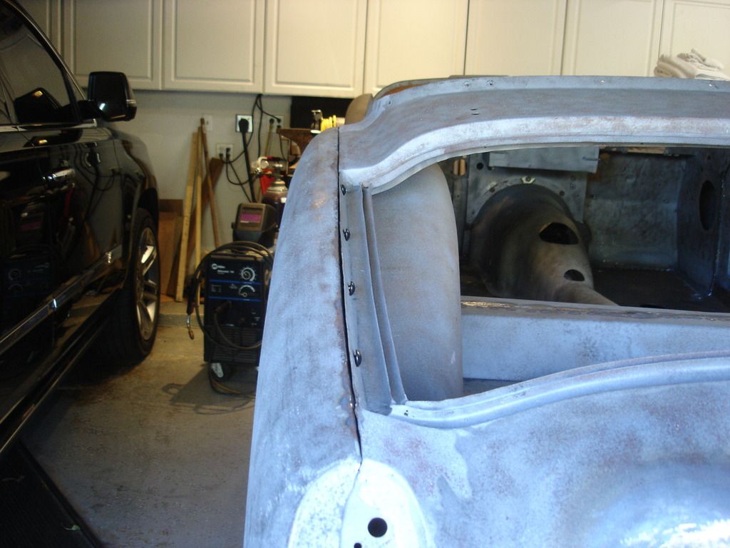
Compared to the panels around the doors, the rest of the car body parts are a breeze to fit. Now, even though I say "breeze", you still need to allow about a full day per panel. In Triumph terms that is easy!?! I started with the left rear wing...


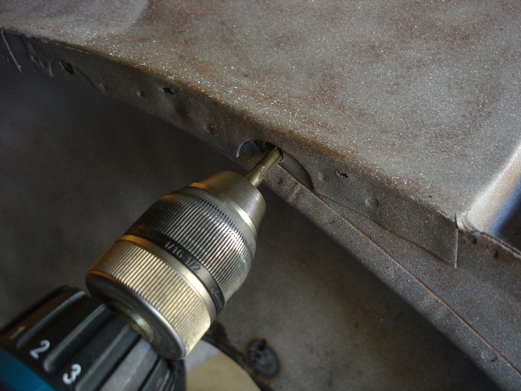
As with all Triumph work, you will have to R and R the panels several times at least during the fitting, so cleaning out hte caged nuts with a tap is almost mandatory. It allows you to hand spin in the bolts without having to work for minutes on each one.


Rear wing installation always starts with the 3 bolts along the rear. The wing is slotted to take these, so you install the bolts about 3/8" out, and the wing will slide onto them.


Slide the wing onto these rear bolts, and then pick one bolt forward to install, just to hold the panel in place while you work.

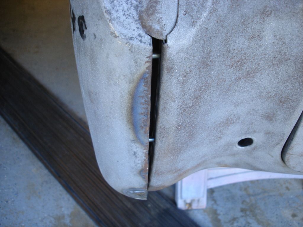
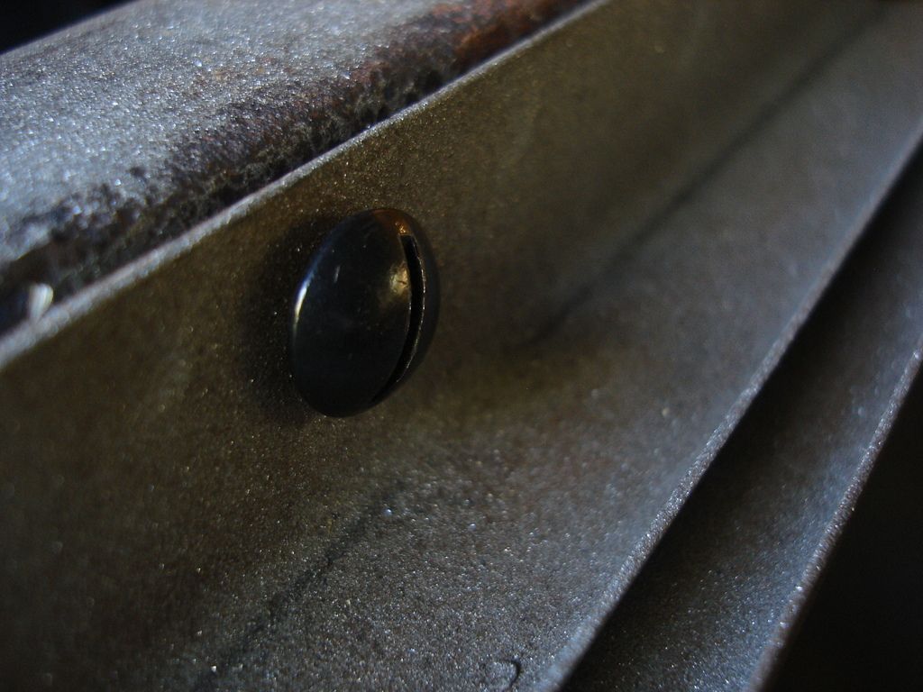
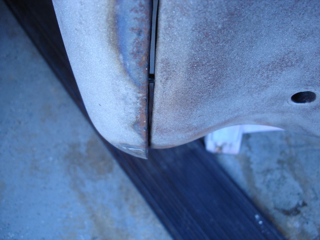
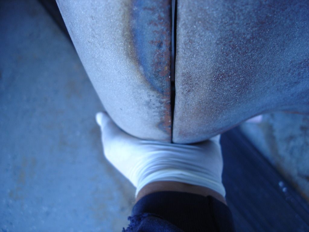
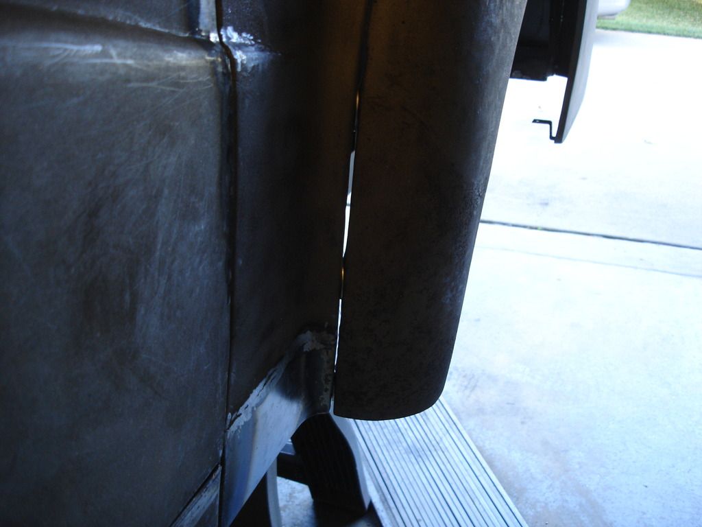
Note: These slot head bolts along the boot do NOT use washers. There is not enough room for a washer or the heads will hit the boot lid.


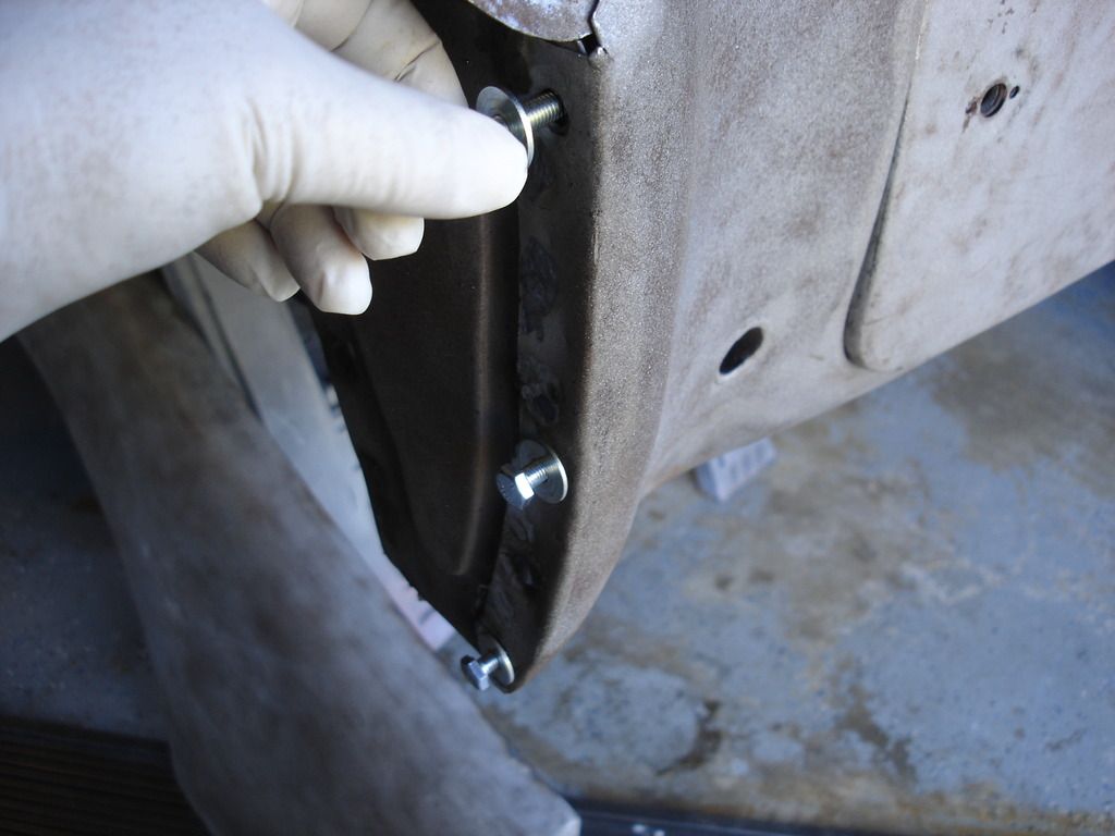
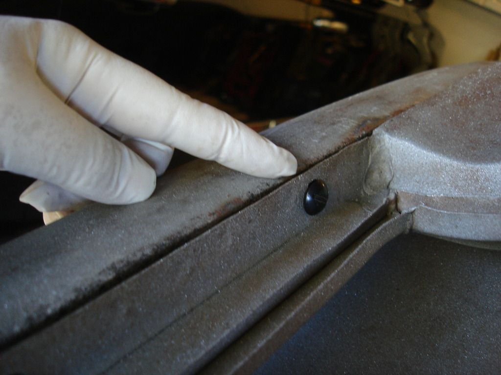
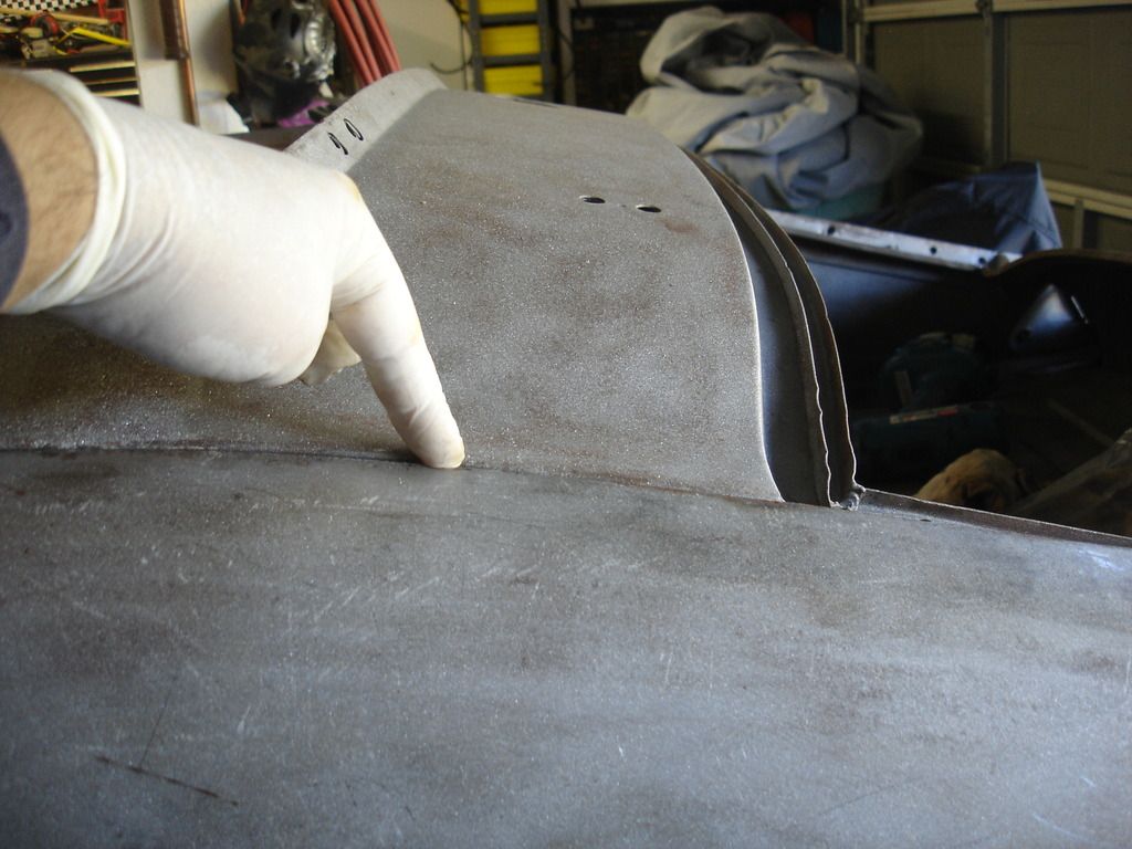
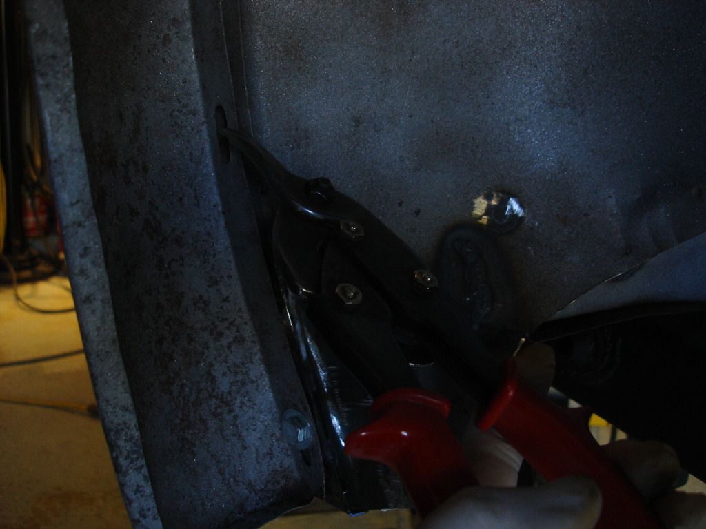
This little bracket goes in the rear upper bolt hole, in the orientation shown. Of course you have to reach under the wing to install it while threading the bolt from above.

Note: You are dealing with 18 gage sheet metal with all of these bolts. DO NOT over tighten them. Just snug is all you need, even for final installation. Any tighter and you start distorting everything, which accomplishes nothing for holding the panels. With 20 bolts per panel, the wings are not going anywhere when the bolts a just snug.


For the initial installation, I am loosely installing all of the bolts in the wing, to make sure they will thread without any clearance issues in the slots. I did this check a year ago, but a lot has been done to the car since then!


Now we start at the rearmost, bottom bolt. Align the wing to match the rear valence in every direction....up/down...in out...and the angle. Once happy, snug the bolt. If it will not align, then the slots are not correct. Figure out which one is holding the wing away from good alignment and open the slot with a burr. Yes, the wing has to come off for that!


Next, snug the middle and finally the upper rear bolts.


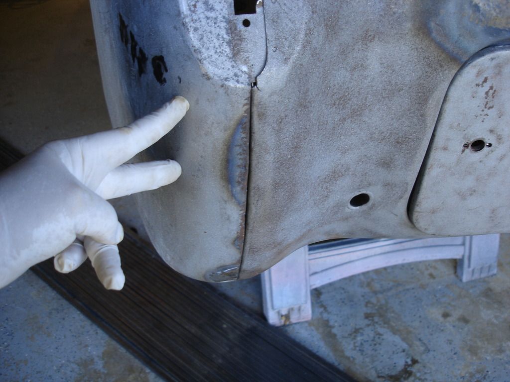
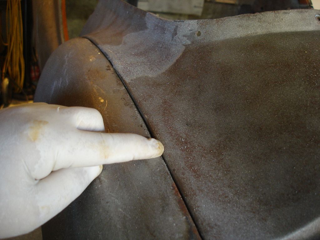
The next bolt to snug is the first one along the rear scuttle, located under where I am pointing. Align the wing and then snug the bolt.

Hint: Once you are sure the bolts will thread easily, I remove them for the following steps. We are going to work from this bolt above forward, one bolt at a time. Each has to be aligned, and it is easier to align them if the ones forward of the one you are working on has play to move the wing around.


Second bolt aligned and snugged.


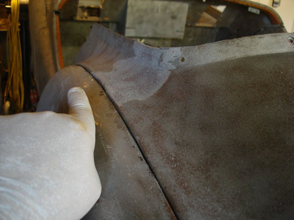
Third...and so on. Align the wing at the location where the bolt is, snug the bolt, and move forward to the next.


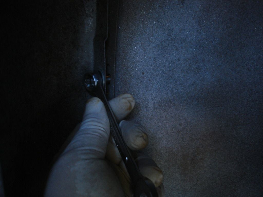
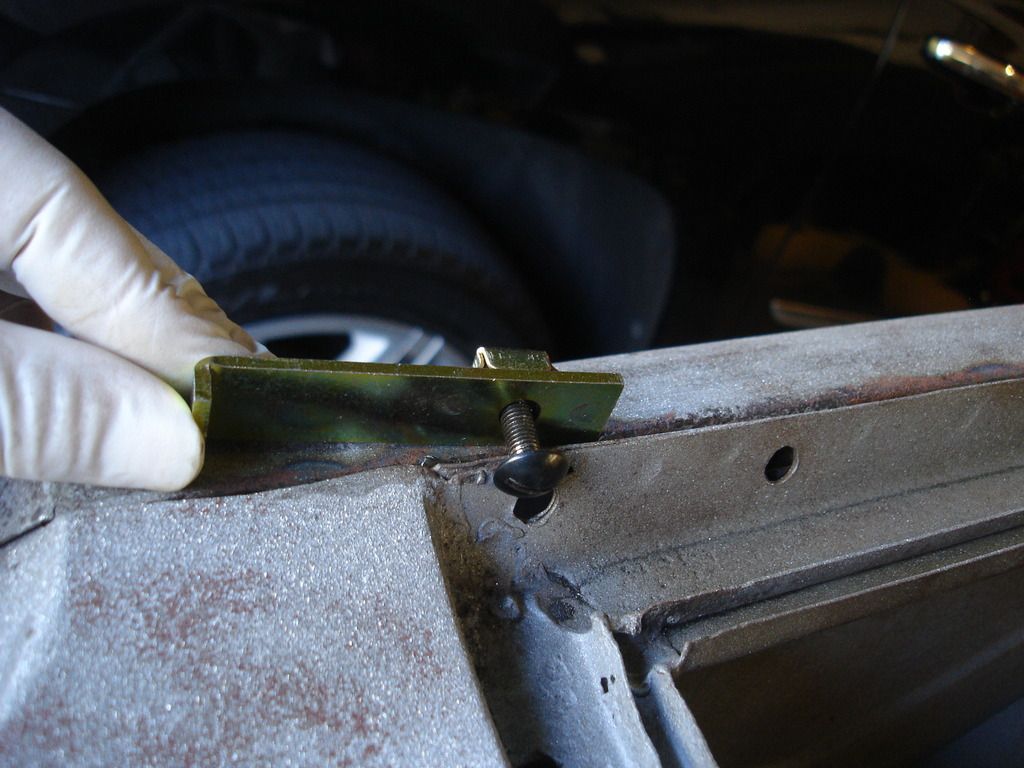
The lower 3 bolts at the front will later also capture the stone guards, which have some thickness. You can see the factory stamped a relief. We need to prevent distorting the relief...so do not do as shown here. Add a washer to give clearance before you snug.


A crow bar occasionally helps t push the panel for alignment.


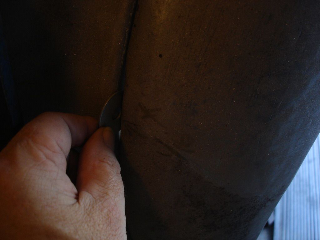
I learned that this was a factory trick. If you cannot get the curvature correct because the mounting flange on the wing is not allowing it, simply snip the flange at the bottom of the offending slot. This allows you to correct the curvature as needed. WIth all the wings I have worked with, I kept seeing these snips and thought someone was doing shoddy work. I finally realized that EVERY wing had the snips!! That's not a coincidence. I believe the factory used the technique.


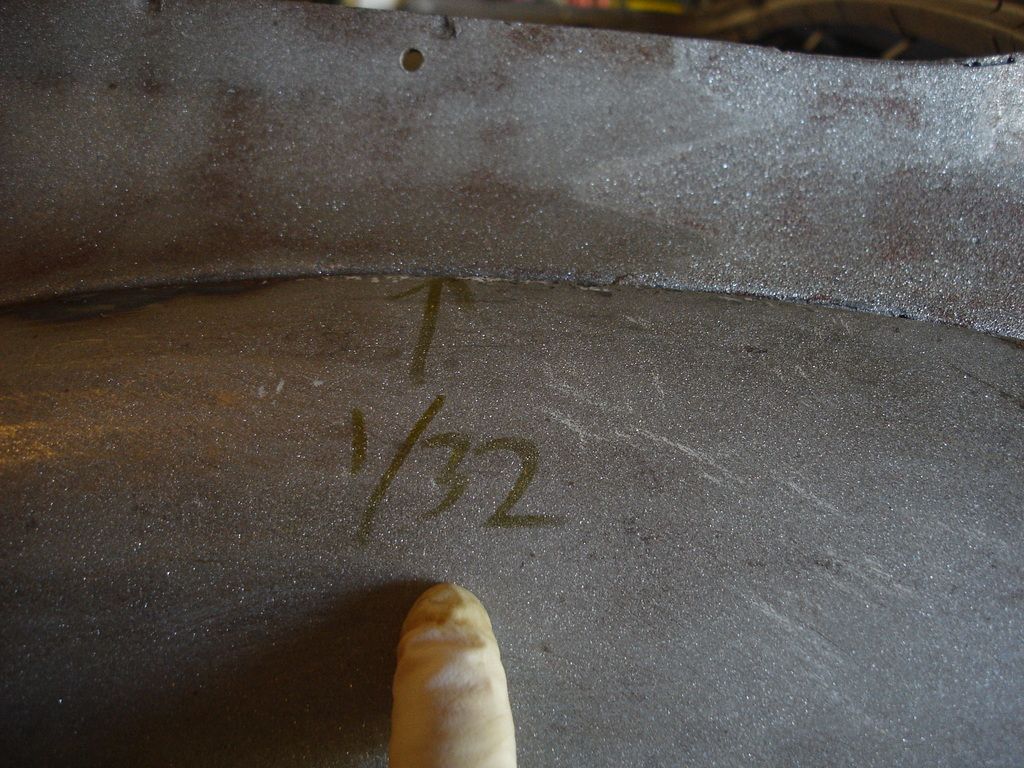
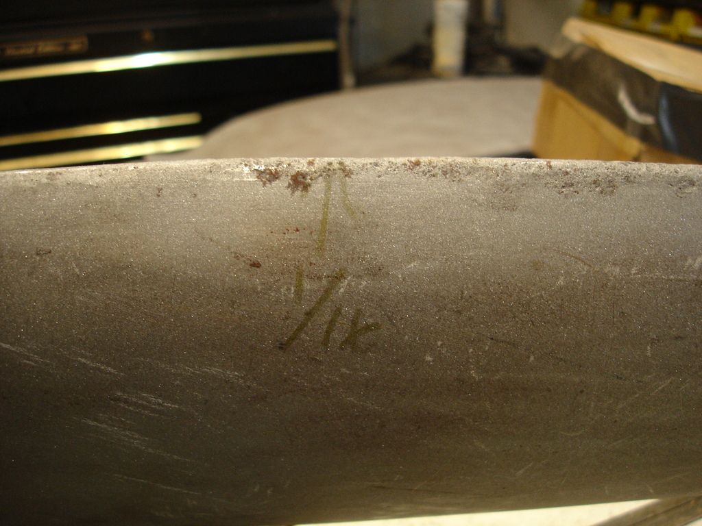
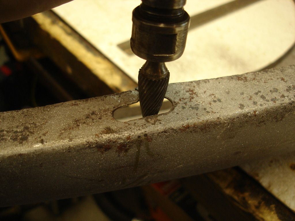
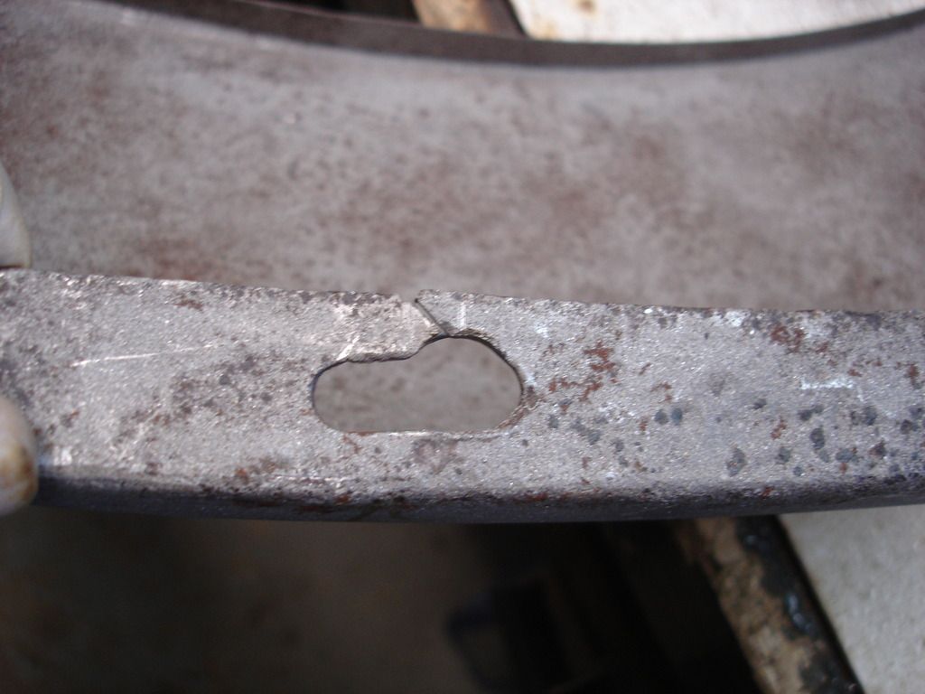
At a few locations the slots would not allow me to align the wing in one direction. I mounted the wing as closely as the slots would allow, and then measured/marked the amount the slot was off. I then removed the wing and expanded the slots the marked amount. The line on the under side of the wing is marking the exact location of the bolt. That way I only had to expand the slot in the exact spot the bolt needed it.


Here is the washer going between the tub and wing for one of the lower front bolts. Again, it prevents distorting the wing where the stone guards will eventually go.


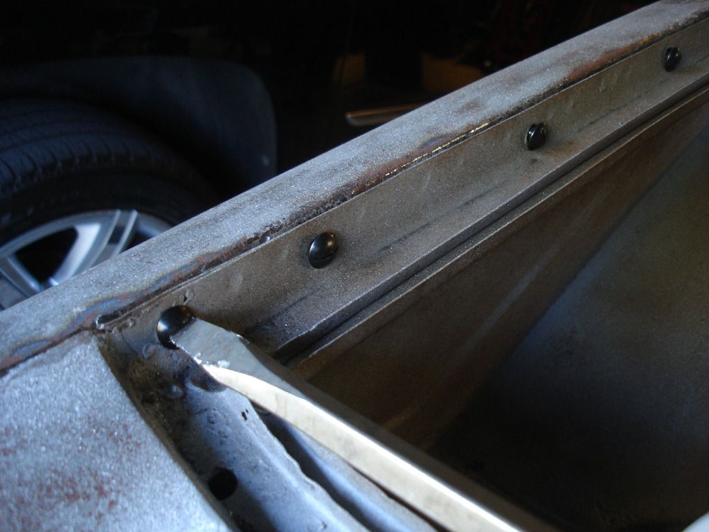
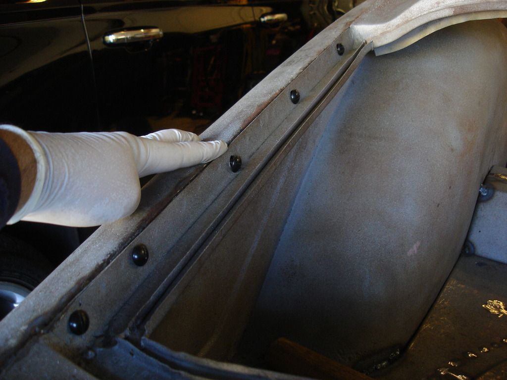
With all the forward bolts secure, We can move to the ones along the boot. Just lightly take up the slack on these for now. We may need to tap this area to match the boot lid...but we can't do that yet.


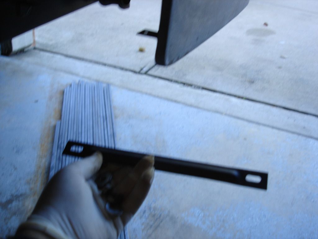
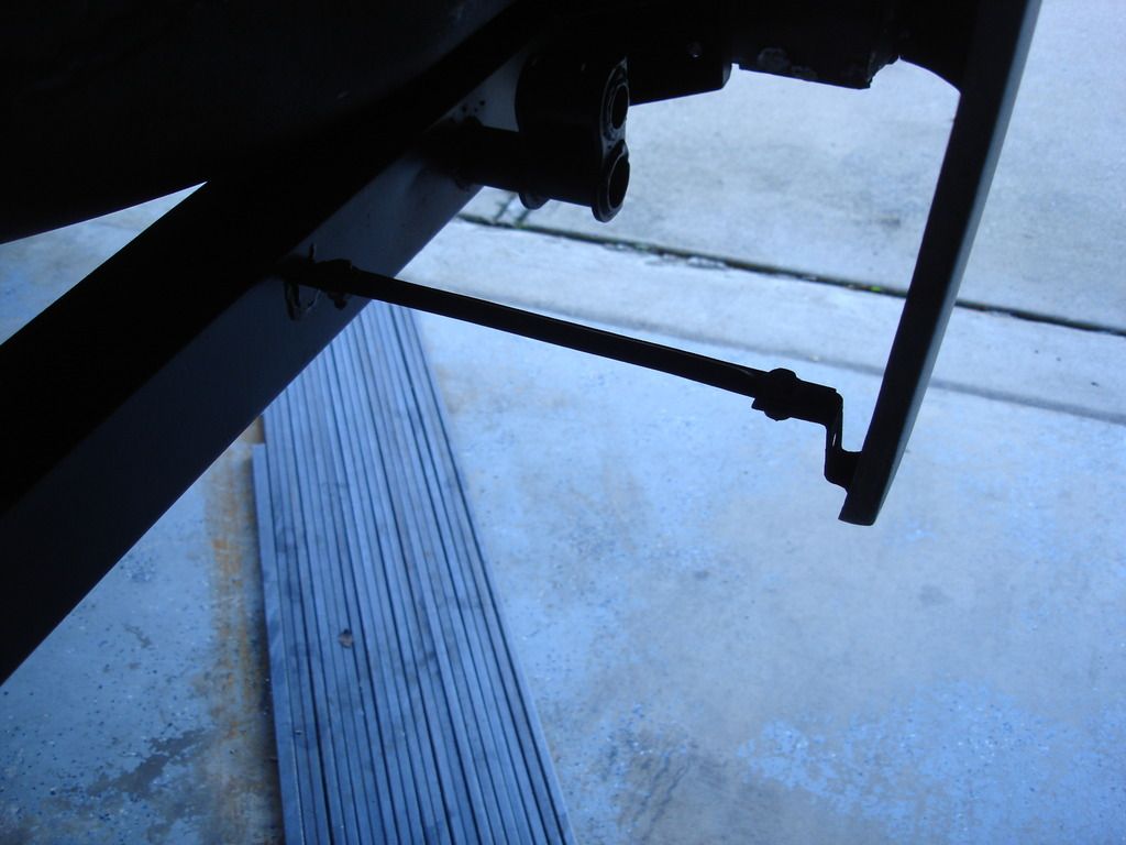
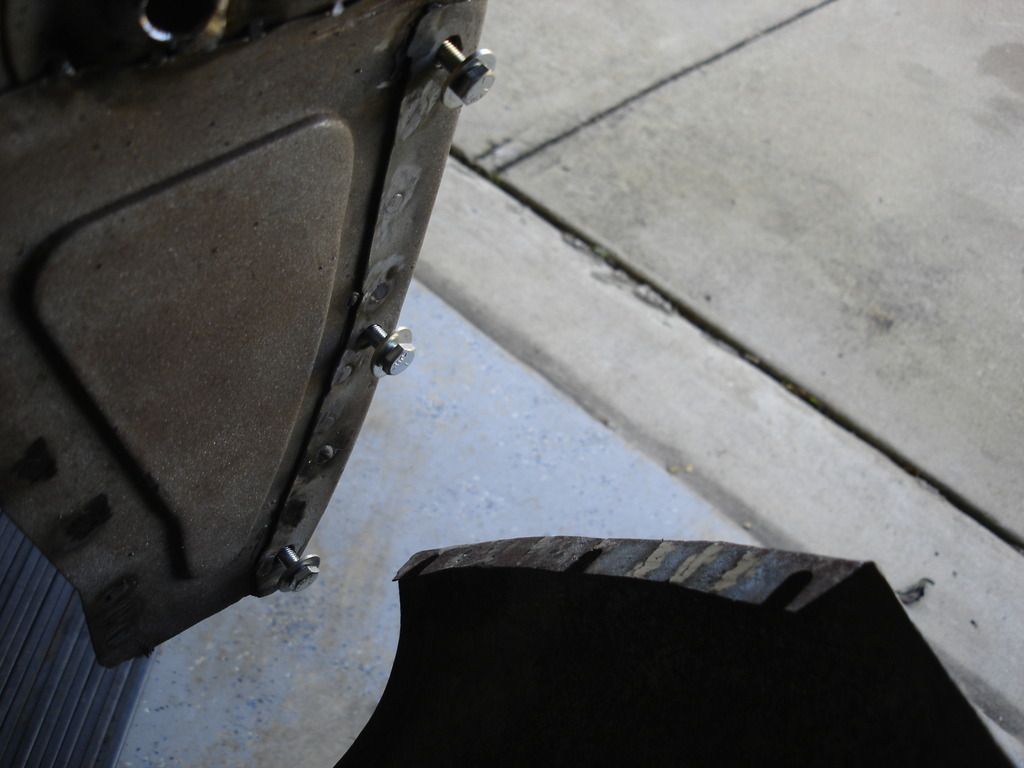
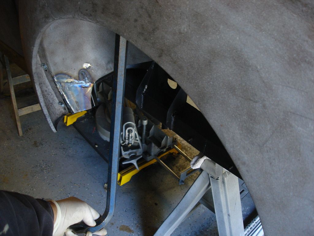
Last, the strut that supports the back of the wheel well goes in.
 
Back
Top