• Hey there Guest!
    If you enjoy BCF and find our forum a useful resource, if you appreciate not having ads pop up all over the place and you want to ensure we can stay online - Please consider supporting with an "optional" low-cost annual subscription.
    **Upgrade Now**
    (PS: Subscribers don't see this UGLY banner)
Tips
Tips

TR2/3/3A Beginning the TR2 Bodywork

M_Pied_Lourd

Darth Vader
Country flag
Offline
Yes, excellent as always! I was playing with my rust bucket tonight as well...

Looking great.

Cheers
Tush
 

carpecursusII

Jedi Trainee
Country flag
Offline
John, take a good look at your sill, specifically the taper where the outer floor edge will sit. I purchased a new sill from Moss and it was not correct for the 2, the taper was too shallow. If you need more info PM me.
 
OP
CJD

CJD

Yoda
Country flag
Offline
Week 59

It's beginning to look like a car again.


Here is the rear of the right inner sill. The tabs are meant to be spot welded to the wheel arches. As with all things, that was wishfull thinking. I had to spend a good amount of time adjusting them to fit.


So, step 2, after the inner sill attachment is the fantail. Here it is on the frame, and I am working on getting the sills to fit the wheel arches properly. A lot of tilting, lowering, checking...tilting, fixing, lowering, checking...and on and on and...


I am using the 2 rear body mounts to align the fantail. The inner sills were aligned to the outriggers. So, once the fantail is fit and all the mounting bolts are centered, then all should be in alignment. It's a theory, anyway.


One thing I made absolutely sure is that the rear bumperette hole in the body aligned with the mounting holes in the frame. Not hard to do...just sight down the tube.


When the fantail is as straight as I could get it, I welded the wheel arches and "B" post bottom to the inner sill.


This is the lower support I made for the quarter panel patch. Once the B post is welded, it's time to install the new quarter panel bottoms. The first step is to install this support.


What I would give for a spot welder!


And, time to install the patches.


Here I have clamped the outer sill to the inner sill. The patch must match the sill. This step insures I won't have to re-align anything later.


Notice the outer sill had to be trimmed at the bottom to fit the quarter. Another reason I saved the quarter patch for now is so I could get the spacing perfect with the sill.


This is a pic of the trimmed outer sill compared to the way it came. Simple but important.


Here is one of the floor panels I got off Ebay. They were advertised as TRF from the 1970's. Thus the surface rust. But otherwise, they are some of hte better floors I have seen. Last car I had to return 2 sets before I found decent floors. I liked the Ebay, as I could see the pics and know exactly what I was getting. The parts suppliers don't have decent pics, so you have to guess at the quality.

The floor lays on the rubber strips we glued to the frame on the inside, and in a slot on the inner sill on the outside. It has to slide in under the quarter panel from front to back.


The floor rides on a tab on the drive shaft tunnel, and then slips under the rear fantail floor. The TR2 floor parts are logical. All panels are layed to prevent water ingress, so the front of each panel goes on top, and the rear of each goes under. Later bodies were not so logical. You can just see the slit in the fantail panel that allows the floor to go on top of the tunnel tab, and then under the rear floor. Here I am just checking for problems. The floor install will come later.


In preparation for the floor install, and before anything gets tacked permanently, I ran a hundred measurements to ensure I was still straight and square. The farthest I measures off was 1/8". That is much better than my last body measured.


Most of my time was spent adjusting the "new" parts. Here I wanted the outrigger bolts to center in the sill mounts, so once I got the measurements as square a possible, I adjusted the holes slightly with a burr.


The outrigger bolts also go through the floor, so I removed the 4 on the right, so the floor will lay down.


Now the outer sill gets welded in place.


And the work gets duplicated on the left side.


Making headway! Still a long way to go, though.


This is important to note. I bought the outer sills off...yep...ebay. As a few of you are aware, there is a variety of outer sill quality out there. The decent repros have this relief stamped in so the front corner of the door clears. Many of the el cheapo repops do not have this relief. I, once again, bought from ebay, as I could see exactly what I was getting.


And, the outrigger mounting bolts are removed in preparation for the floors.
 
OP
CJD

CJD

Yoda
Country flag
Offline


The towel is to prevent scratching my frame.


The floors I bought do not have the caged nuts on them. So now is a good time to install those. 6 for the seat and 4 for the tunnel.


Now the floors lay in the slot and slide to the rear. I wish it were that easy...a lot of trimming had to take place to get them to fit right. My goal was to have the mounting holes in the floor align with the outriggers and center frame mounts.


This is a little notch to make fitting the inside rear corner easier.


This pic shows why you have to slide the floor from the front. This is the inner quarter panel. It is pried out a bit. Once the floor is in place, this will get bent back down and welded to the side of the floor.


The best laid plans... I installed a caged nut here, but the cage is actually already inside the drive shaft tunnel. I had to pop this one off!


The inner sill is the backbone of the body. So, once the floor fit to my satisfaction, it gets welded to the inner sill first.


This is looking from front to back at the front of the right inner sill. You can see the ledge that holds the floor. Before welding, make certain that the floor is actually sitting firmly on this ledge. You will be in a world of hurt later if it does not, and it is not obvious unless you sight down the sill like this pic is doing.


Now the quarter panel is bent back into place in prep for re-welding to the floor side.


This has nothing to do with the build. I just happened to notice that the body and frame had become magnetized. Kinda weird how it was playing with the metal grindings!


Here my hole welds are ground flat(ish).


Here is the corner of the rear floor and the shaft tunnel. I will NOT weld this now, as I want the body to remain a bit flexible until I align the front clip and doors. Once all the main tub parts are aligned and installed, then I will finish the inner floor welds. Ask me some time how I know this is important?!?


And of course...repeat on the left.


I cannot emphasize re-checking all your measurements before and after each operation. It is unbelievable how welding in one area can throw off another. At this point if a measurement goes off, just wallop the offending part with a big rubber hammer. If you try to go two or more steps and then check alignment...you WILL be sorry.


This is an additional mounting bolt towards the front of the floor.


And this is another towards the rear. Notice the mounting hardware from TRF supplied a phillips bolt. Not correct. In fact, only about half of the mounting bolts/nuts required were in the kit. Just goes to show ya...all of the big three have their short comings!?! Later I will dig in my Triumph bolt box and find the "correct" slot head screw for this...along with other "correct" bolts for mounting the body.


Alas...I know I can be anal. But, I will know that if anyone peals up my carpet they will find only the proper afixments!!


I waited for my son to wake up Saturday morning, and he brought the front clip down with me from the family room upstairs. It is beyond nice to get these Triumph parts out of every room in the house. It is phenomenal how such a small car can take up sooo much space when in pieces!


Now we start another session of fitting, tilting, and fixing to get the front clip to fit properly.


Here you can see that the floors come with extra metal at each end. The front should be trimmed even with the front of the inner sill.


This is the clip laying on the floor. That floor lip must go above the firewall on the clip. Again, so the wind will tend to suck water out of the car rather than force it in. The floor needs trimming to fit inside...
 
Last edited:
OP
CJD

CJD

Yoda
Country flag
Offline


This is the very front body mount. In the following pics I ran into a snag, as the body, although aligned at floor level from front to rear...in every way I could measure...was perfect. The problem was that the body was 1" longer than the frame, no matter what I did to check it. I could force the right mount into place, but I spent most of a day trying to force the left front mount, to no avail.

My conundrum was finally solved after sleeping on the problem. It occurred to me that, although I measured everything I could on the frame plane...I had forgotten about tilt!! Essentially, when I repaired the substantial crash damage to the front clip, I had gotten the side kick panels off by about 3 degrees. Completely unnoticeable...but enough to "lean" the clip forward...adding 1" to the length!

The lesson is to use more beer and more sleep to handle difficult body problems.


Sooo...to prevent making my mistake, use the doors to align the front clip. Since the door mates with EVERY other panel on the side of the car, you must fit the parts to the door. The door allowed me to see the "tilt" issue I was having. Here I am fitting the hardware to the door to get to work.


The nut plate has lots of room to move, but I had to open up the screw holes to allow enough adjustment to get the rear of the door set correctly.


I set the rear lock plate to adjust the bottom and rear gaps for the door.


Off. I had to grind, and weld and grind to adjust the gaps. Very few came out right the first time...typical for a TR2/3!!


This is the front firewall of the clip. If you look to the right, you will note that the clip is tilted upward at the front. At first I tried to "force" that to zero, which caused my front mount problem. Once the door was "set", I then realized that the clip needed that upward tilt. My repair was what was off.


Now I'm making headway.


The latch is controlling the rear door gaps, but the front has to be held up until the clip is welded in place with the "A" pillar firmly attached.


Now I am shimming the floor up to insert the firewall under the front. I thought once would do it...wrong. I eventually bent the lips to engage easily without shimming the floor. I must have tilted/engaged the clip 50 times getting it aligned right.

Gotta go eat dinner with the family...I'll take the story up shortly...
 
OP
CJD

CJD

Yoda
Country flag
Offline


This is how the front floor/firewall meet.


This is the pretty bottom flange I put in the front clip side panel, including holes to weld the panels to the floor. This pretty flange is also the source of my misalignment.


Holes to weld the floor to the firewall flange.


Here is the correct slot head body mount bolt.


And this is how the original body bolts looked, compared to what comes in the mount kit. In addition to a "modern" head grade 5 marking on the new bolt, there is also no point to help install the bolts. I found all the correct hardware. I ran each one through a die and will later bead blast them before final assembly.


Here I am taking care of the rear door gap that was off in a prior pic. I had to weld one side and shorten the other by grinding. It takes a lot of time, but it's the only way to get your door gaps perfect.


Like this...(the rear and front gaps. The bottom is set by adjusting the lock plate at the rear and the hinges at the front. )


The door and sill rear seams need to also align.


The front of the door must align with the indention in the sill. This is a true pain to fix if they do not.


And, after an entire day and a half fitting the doors, it FINALLY becomes obvious that the front clip needs to rotate to the rear! Now why couldn't I see that before??

Initially I was racing through the build, and assumed that if the bottom of the door measured correctly that the front clip had to be right. There is no "rushing a TR build. The doors have to be fit before the clip can possibly be aligned properly...and this pic shows why!


Tilted up...again! I have taken measurements for the amount of correction I needed, so now I have to fix the angle on the side kick panels. They won't be quite so pretty once I'm done. Here goes...


The old flange gets straightened out, so start from scratch.


And it gets re-bent using sheet metal vice grips, to the new dimensions. The correction amounted to making the side panel shorter at the rear, and about the same as it was at the front.


This is how the door MUST align to the front scuttle. What I am referring to is the vertical alignment. Notice the "in and out" alignment is off at this point. I am not concerned with that at the moment. It will be dealt with once the scuttle is perfect.


Once the front clip is merely tacked into place, this time so the front body mounts actually align!?!, then we can adjust the door to scuttle gap. Once again, it took a lot of welding and grinding. No short cut for this job.


And that's it for another week. I still have not welded the interior floor seams yet. Once again, it is important to save those until you are completely happy with all of the alignments...and even then, never weld more than 15 minutes between alignment checks.

Cheers until next week!

Now it finally looks like a tub again.
 

M_Pied_Lourd

Darth Vader
Country flag
Offline
One word John. Superb!

Fantastic documentation. Thank You.

Tush
 

DavidApp

Yoda
Gold
Country flag
Offline
Wow that was a busy week. The job being done right.

You highlighted so many issues that the PO left me with.

Will you brace the tub when you lift it off the frame? I am considering tacking a brace in the door gaps before I lift the tub to try to maintain the gaps if I can.

Great job.

David
 
OP
CJD

CJD

Yoda
Country flag
Offline
I've been working on the "grunt" stuff for so long that I am only now beginning to formulate a plan for the painting. I know there are 2 schools for working with a lone tub off the frame...I'm in the no brace school. I've found the tubs to be plenty rigid for moving around the garage/yard without "springing". The inner sill is made of the same thickness metal as the frame, so it is a relatively sturdy body. I would not put it on a trailer and go bouncing down the road, though, as there are plenty of stories of tubs that got really bent doing that (although the way they were strapped to the bed may be a big factor). Even if there is a bit of "droop" when the tub is lifted off, the frame will straighten it right back up once it's re-attached.

It's funny you mention "PO" issues. If I had to rank the problems I ran into, the PO issues are at the top, followed a close second by the quality of new parts.
 

DavidApp

Yoda
Gold
Country flag
Offline
Hello John

Looking at your outer sills I may replace my drivers side sill. It was fitted by the PO and does not have the formed area for the door clearance. Still working on getting a good fit to the wings,door and dogleg.

Taking a break for a few weeks doing paying work. (Helps with TR parts)

David
 
OP
CJD

CJD

Yoda
Country flag
Offline
Week 60

This week was spent tidying up the tub welds. I made absolutely sure that all the mounts were secure, and that all of the mount bolts were generally in the center of the body holes. On the TR3 it was frequently a pain to remove/install the mounting bolts, as the body holes were off center and had to be "convinced" to go in. On this TR2 body all the bolts slip right in with no alignment problems at all. We'll see if it stays that way when it all comes apart for the paint?!?

So...with everything lined up, I began finish welding all the interior seams:


This is the seam where the drive shaft tunnel meets the floor.


Terrible pic, but this is the rear floor too fantail seam.


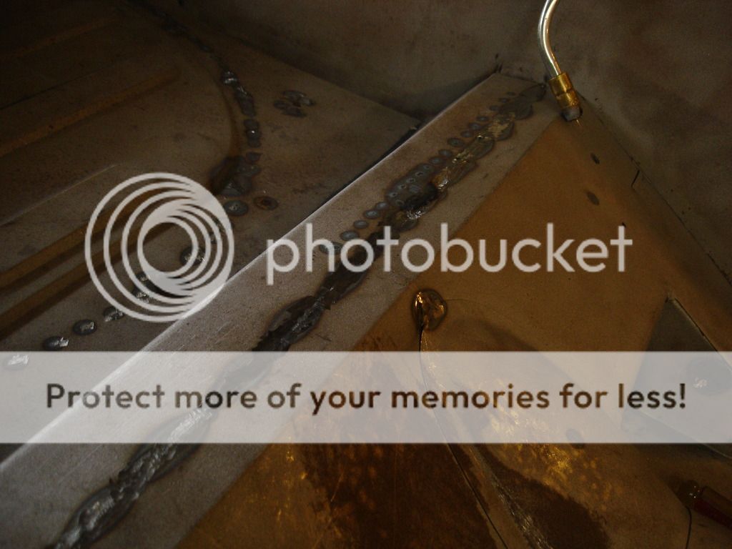
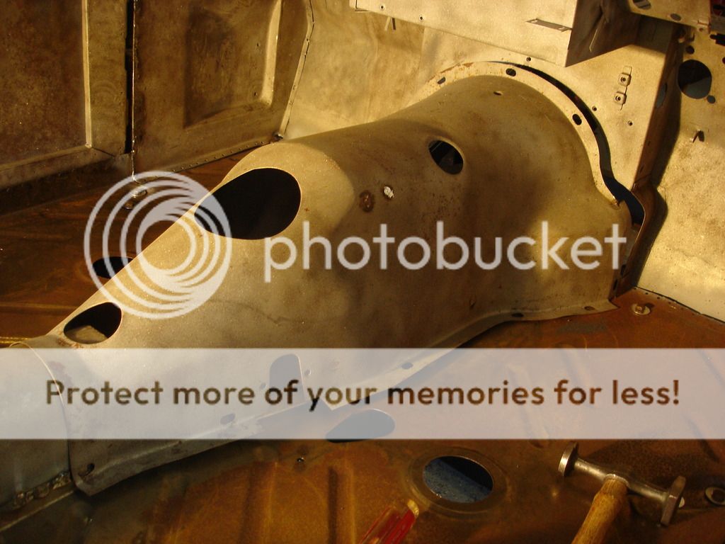
The PO had replaced the boot floor, but it was only partially installed. Here I have seam welded the floor to the under gas tank portion of the fantail floor...and you can see were I spot welded the spare tire tub underneath.

This completed all of the welding in the tub...except the front floor to firewall. We will need to install the transmission tunnel before that can be done.


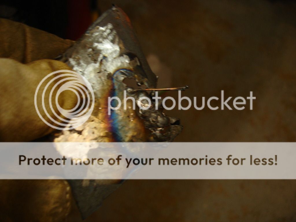
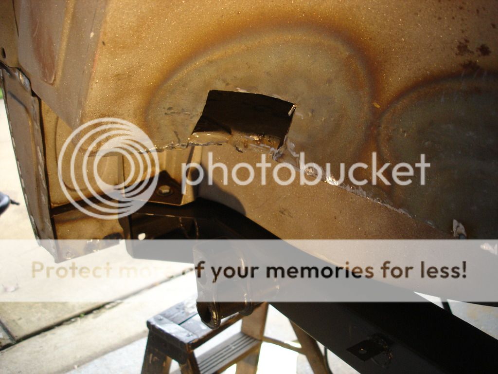
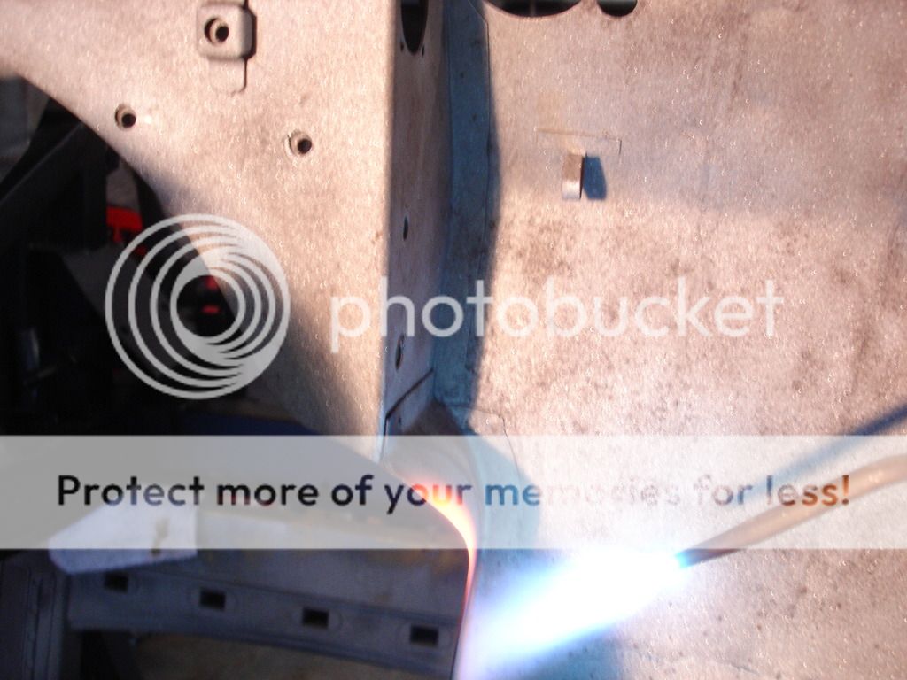
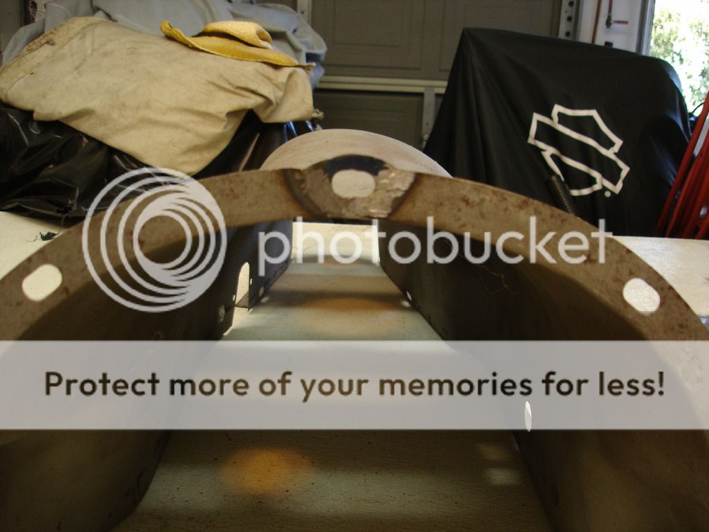
This is a chunk of the right inner wheel well. When I put the light on the wheel well, there were some tiny pin holes from the patch a PO put in. I have no idea WHAT he did, but every time I attempted to fill the holes with weld, the welder cut through and made a larger hole. I fixed that, and when I ground it down...more pinholes!! This process went on for about 3 hours. I finally concluded that the PO must have used brazing flux on the repair. You do not need flux for steel welding. If you use flux, it flows and fills parts of the weld, essentially creating voids. I finally realized I was losing the war, so the above pic is the section of PO repair that I finally completely cut out to start from scratch.

Steve once asked how to know whether to fill weld a hole or to patch. This shows that sometimes you don't know until you try.


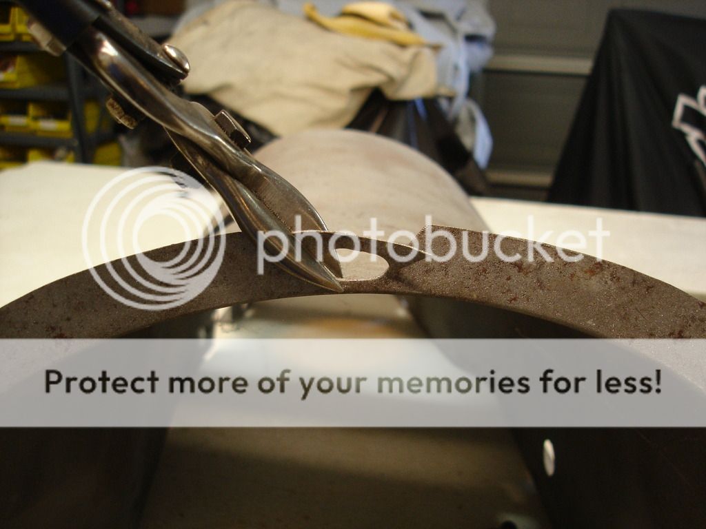
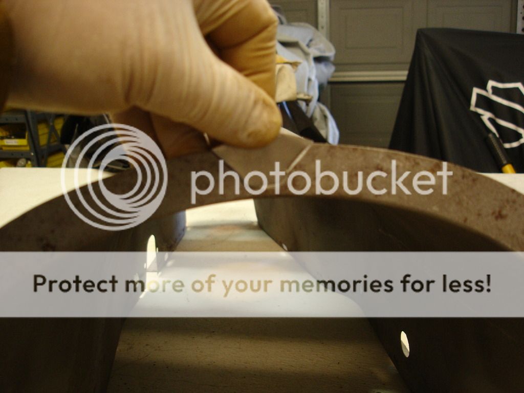
So here I am fashioning the curve for a new patch.


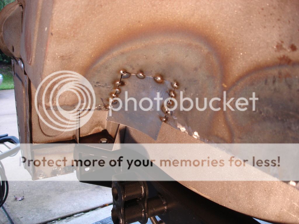
The sad part is that the entire patch took all of 15 minutes to cut, fashion, weld, and grind to fit. 15 minutes after trying to repair the PO patch for 3 hours! I guess that's an example of tunnel vision?!?


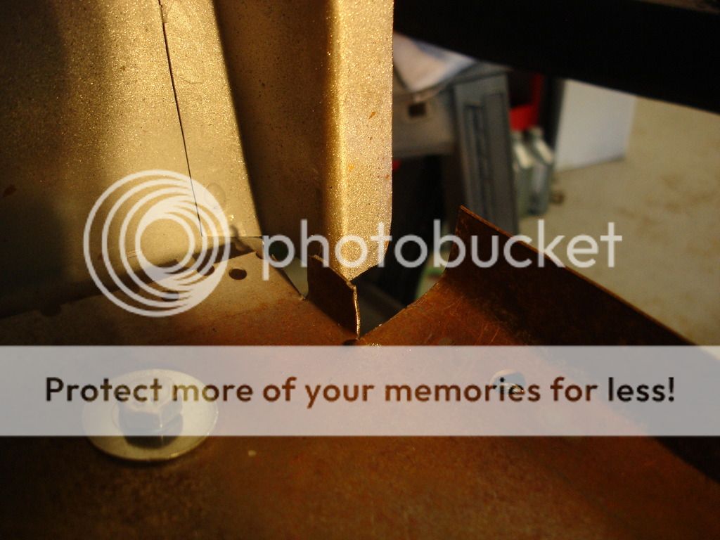
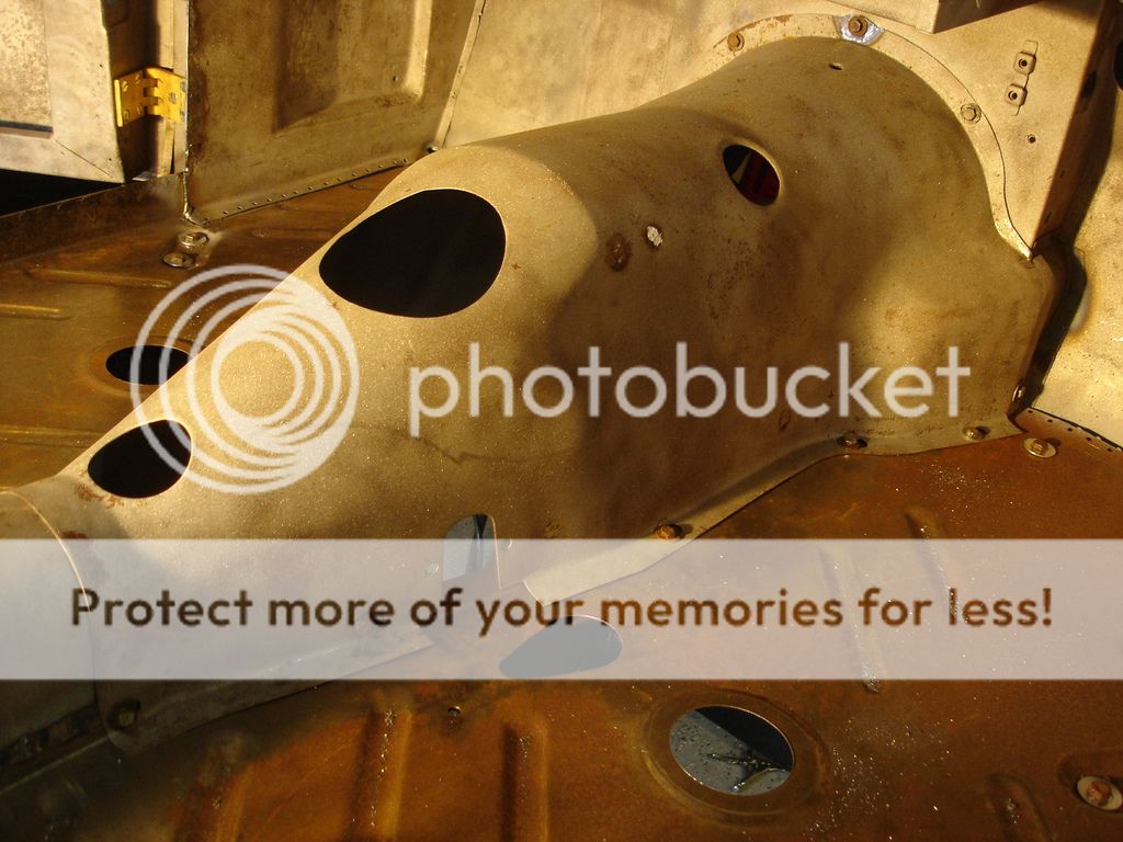
Before I welded the front floor seams, I wanted the transmission tunnel in place. This is to ensure that the floor to firewall joint is at the correct height...especially if you remember the extent of the rust repair to the firewall in this area.


In this pic I am matching the right side tunnel to the firewall. A little hammer and dolly work on hot metal makes them fit perfectly.


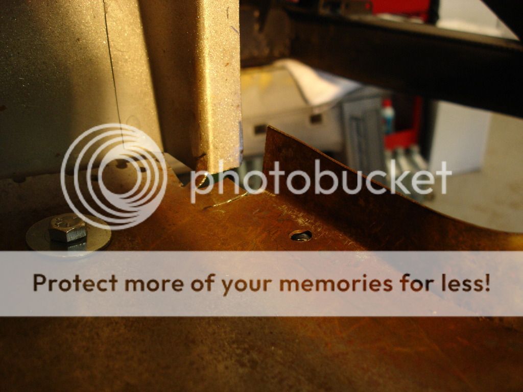
This is the left side at the floor seam. It required a little trimming. As the tunnel is installed, it will pull the floor up to the correct level for a permanent weld.


The holes in the floor at the rear of the tunnel did not line up. I filled the mis-aligned holes and re-drilled them in the correct position to align with the caged nut inside the shaft tunnel.


As with all bolts and nuts, they get "dressed" with taps and dies to make sure the bolts spin in easily during hte 50 or so install/removals it takes to fit these parts.


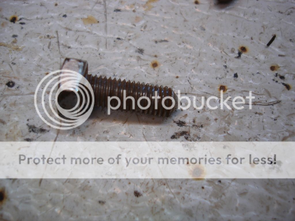
Here is the standard body bolt...1/4" - 28. They have a point. I have not found replacement bolts that have the point.


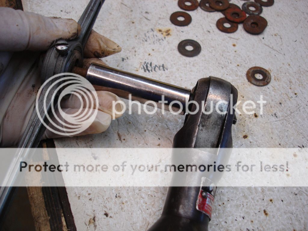
This is an example of the head of an original bolt. The original heads were not necessarily consistent, but they all had markings for their period. Modern bolts have the grade markings that were not present on older bolts. So, I will dig in the bolt box for all of the original bolts I can find to install in visible locations...like under the bonnet. I will have to use newer style bolts on other locations that do not show.


Every used bolt gets cleaned with a die before I attempt to use them.


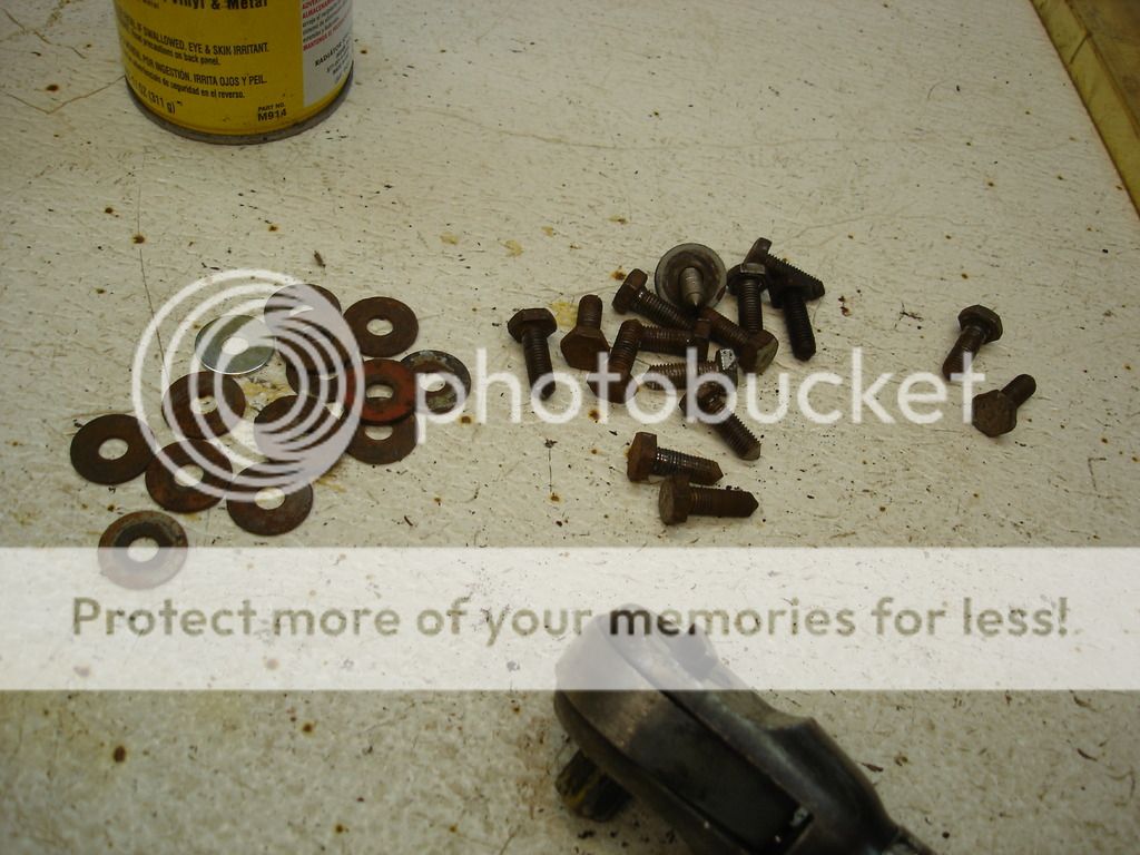
Here's the pile of bolts I will use on the tunnel. After they come out before painting, I will bead blast them so they look like new.


On the first fitting of the tunnel, The center top bolt did not line up. Here I will have to modify the slot int he tunnel to match the caged nut in the firewall. Not standard, but this area is not readily visible, and if anyone strains way down to see it, it will look like it was factory. Again, I have learned that I want all fasteners to EASILY thread in and out, since I have learned that these parts have to be removed many, MANY, times during fitment, painting, and regular MX. Much easier to fit them right now, than to fight them for hours later.


Now the slot will line up perfectly.


Now we're getting somewhere! The right side of the tunnel is good.


This is the area we heated and shaped...always worth the effort.


Notice that the tunnel has pulled the floor up into position...Now the floor to firewall seam can be welded permanently to the perfect location.


A shot of the rear section.
 
OP
CJD

CJD

Yoda
Country flag
Offline


The following few pics are for newbies to the TR's. What hole is what. This one is the access hole for the transmission dipstick. It was on all TR2's, and early TR3's. After that it was eliminated.


The large hole is for the shift lever.


The smaller hole behind the shifter is for access to grease the front drive shave universal joint.


This is the relief for the speedo cable on overdrive cars. The boot for the handbrake covers it. Although it is present on all cars, it is only used on the OD optioned ones.


And the handbrake hole. The pointed part (sorta) at the rear is where the OD speedo cable re-enters to clip to the frame underneath.


The lone hole on the left tunnel is for access to the tranny fill plug. With practice you can become proficient working through the hole to fill the tranny with a tube running through this hole.


Finally, for the end of the week, I held up the right wing. Not a great fit, but it could be much, much worse!


Too dark, but this is looking at the bottom bracket on the wing from the front looking aft. The bracket was fashioned completely from scratch, and will need to be bent downward to fit under the inner sill. Right now it is hitting about 1/2" too high.


This is the same bracket from the rear.


Of course, always door gaps!


This is an interesting shot. Notice that the scuttle drip rail feeds into the drip rail on the wing. These must line up like the pic to keep the water from running inside the engine compartment and all over your solenoid and electrics.

That's it for the week!
 
OP
CJD

CJD

Yoda
Country flag
Offline
I was sitting here proofing the posts, and noticed the long rust drips on my right door and wing. Texas has it's problems, but one thing I love having grown up in New Orleans, is that metal doesn't rust here! If you have been following, the door was repaired over a year ago and has sat in storage with no paint at all. The rust "drips" are exactly that...the storage shed has a leak and those are where the water ran down the door and wing. Otherwise, there is no rust at all! In New Orleans you would get surface rust if you left bare metal overnight, let alone an entire year!

I'm getting spoiled with the climate here...
 

DavidApp

Yoda
Gold
Country flag
Offline
Hello John

Making great progress.

I am going to suffer with hole alignment issues on my car. Issues left by PO. they line up but take some help.

I did have the same problem with the front wing lower flange and ended up putting a little bit of a downward angle on the wing portion and matched it on the piece that bolts to the inner sill.

David
 

M_Pied_Lourd

Darth Vader
Country flag
Offline
Looks great John.

Question for you. On the back of the tranny tunnel, where the handbrake boot fits to, are there cage nuts welded on the inside for the two fasteners? I don't think that there are any I remember what a bitch it was to do those two fasteners up to hold the plate unto the boot.

I think on my next one, I'm going to weld a couple of nuts on the inside of the tunnel to make that easier...

Cheers
Tush
 
OP
CJD

CJD

Yoda
Country flag
Offline
I am pretty sure the tranny tunnel takes a couple of those clip style nuts...made from stamped steel to take a sheet metal style screw. I'll check my pics to make certain and post a pic when I find it.
 

PatGalvin

Jedi Warrior
Country flag
Offline
Hey John

I also had to add some metal to the top hole of the tranny tunnel to make it mate up with the firewall/bulkhead and line up with the captive nut on the other side of the bulkhead. I ultimately figured out that I had probably installed my floor pans too low in the tub so that when the tunnel sat on the floor pans, it was too low to mate up with the top screw hole on the bulkhead. That was a PITA. When I was doing final assembly of my tunnel, I realized the tunnel did not fit really well to the floor or to the bulkhead. So, I used a strip of oil-resistant foam along the floor and on the bulkhead. This sealed up really nice and tight. I ultimately cheated and used a few sheet metal screws to finish holding down the tunnel. Not as perfect as what you have done, but it works - no squeaks and air tight (well, mostly...).

Thanks for a truly sensational chronicle of your body work adventures!

Pat
 

M_Pied_Lourd

Darth Vader
Country flag
Offline
I am pretty sure the tranny tunnel takes a couple of those clip style nuts...made from stamped steel to take a sheet metal style screw. I'll check my pics to make certain and post a pic when I find it.
That makes sence John. Wish I would have thought of that. For some reason, I was fixated on using set screws there.

Oh, and if you happen to run short of original hardware for the areas that show, let me know and I'll see what I have that might help you out.

Cheers
Tush
 
OP
CJD

CJD

Yoda
Country flag
Offline
David...I'll have to bend that lower wing flange down like you did. It didn't look like it would be a problem, but we'll see. I always hate to say "no problem" on these hand built cars!

Pat...you're probably right about the upper tunnel slot. The entire left firewall on my car was pretty mangled, so I feel lucky that this is the only "mod" I had to do. The rest of the bolts fit now, but I am certain they are not perfect after all this car has gone through.

Dave, I did find a pic...although not great. If you zoom in, you can just see the rusty clip in the left hole. The right hole still has the original style slot head sheet metal screw in it. I really appreciate your offer for "correct" bolts. When I get to the final assembly stage I'll get in touch. It's would be a shame to put so much effort in and then settle for obviously modern fasteners.


Thanks again to all of you for showing support...it has REALLY helped keep me going to this point!!
 
Similar threads
Thread starter Title Forum Replies Date
RJS TR4/4A Beginning Cyl Head Removal - Questions Triumph 21
W Beginning to sale pieces and parts Spridgets 8
B T-Series Beginning TD Restoration MG 4
P Beginning restoration, advice please Spridgets 28
M steering wheel restoration-from the beginning Triumph 17
JPSmit The beginning of the end Spridgets 10
B TR6 Totaled TR6 saga...a new beginning Triumph 17
J project beginning Austin Healey 13
DrEntropy I'm beginning to evaluate this: Lotus 6
RickB MGC MGC GT - beginning to restore this old girl. MG 16
Branson Beginning of my restoration - '65 MKIII Spridgets 77
Nanhook TR2/3/3A TR2 shoes Triumph 2
CJD TR2/3/3A TR2 Annual Triumph 6
1955TR2 TR2/3/3A TR2/3 Oil Leak Where Oil Sending Pipe Connects to the Block Triumph 8
S TR2/3/3A WTB a tr2 original grill Triumph 0
S TR2/3/3A differential hubs early tr3 and tr2 Triumph 22
P TR2/3/3A TR2 Horn Mounts Triumph 7
S TR2/3/3A Tr2 and early tr3 differential. Triumph 10
mctriumph For Sale Tr2/3 scuttle mechanism Triumph Classifieds 7
S Wanted tr2 original grill Triumph Classifieds 10
J TR2/3/3A TR2 Fitting/mounting rear wing Triumph 11
A TR2 Transmission overhaul Restoration & Tools 0
D TR2/3/3A TR2 Flying Mile question Triumph 11
S TR2/3/3A tr2 muffler clamp Triumph 10
Southwarks TR2/3/3A TR2 door help! Triumph 2
G For Sale NEW PHOTOS: Triumph TR3 Chassis Frame + Front Suspension, Fits TR2,TR3,TR3A,TR3B Triumph Classifieds 1
P TR2/3/3A TR2 Headlight Trim Question: Triumph 8
A Wanted Girling Axle for TR2 Triumph Classifieds 5
J For Sale Triumph TR2 or TR3 elbow trim Triumph Classifieds 0
S TR2/3/3A tr2 and tr3 back trim above the back cover Triumph 0
KVH General Tech Heater and Vent Control Cables--TR2 thru TR4, and more . . . Triumph 3
S TR2/3/3A early tr3 and tr2 kick panels Triumph 3
S TR2/3/3A TR2 and early TR3 wipers Triumph 7
S TR2/3/3A tr2 Triumph 18
newmexTR3 For Sale TR2-4 performance valve springs, collars, exhaust seats, cotters Triumph Classifieds 0
J For Sale Triumph Tr2/3 seat foams Triumph Classifieds 1
J For Sale Triumph TR2, TR3, TR4 CAM SHAFT FOR SALE Triumph Classifieds 0
K For Sale TR2-TR4 Camshaft Sprockets...New...1/2 Price Triumph Classifieds 0
C TR2/3/3A TR2 Axle/wheel bearing removal Triumph 2
T For Sale TR2 - TR3 Gas Cap for sale Triumph Classifieds 1
71TR6 Set of 4 TR2/3/4 Connecting Rods Triumph Classifieds 0
P New member TR2 carpets Triumph 7
S TR2/3/3A Tr2 hood Triumph 8
W TR2/3/3A TR2 wiper motor mount Triumph 1
TRopic6 For Sale TR2/3 Brass Fuel Shutoff Tap [for parts] Triumph Classifieds 0
J For Sale Triumph TR2 TR3 TR3A New Moss Motors Black Karvel Style Carpet Kit Triumph Classifieds 0
S For Sale Triumph TR2/TR3/TR3A/TR3B Workshop on CCD/ROMManual – 1953 - 1962 Models Triumph Classifieds 0
Leatherman Wanted Red and black TR2 / 3 front emblem Triumph Classifieds 6
Jim_Stevens For Sale New TR2-3A inner sill assemblies Triumph Classifieds 3
C TR2/3/3A TR2 Chassis Clips Triumph 4

Similar threads

Top