
-
 Hey Guest!
British Car Forum has been supporting enthusiasts for over 25 years by providing a great place to share our love for British cars. You can support our efforts by upgrading your membership for less than the dues of most car clubs. There are some perks with a member upgrade!**Upgrade Now**
(PS: Upgraded members don't see this banner, nor will you see the Google ads that appear on the site.)
You are using an out of date browser. It may not display this or other websites correctly.
You should upgrade or use an alternative browser.
You should upgrade or use an alternative browser.
TR2/3/3A Beginning the TR2 Bodywork
- Thread starter CJD
- Start date
John that is just plan fantastic, I am over the top impressed. Have you had your hand tools a long time and or are those hammers still available on line somewhere. I have a cheap starter set with red fiberglass handles for 20 bucks, and I want to upgrade. I noticed that bottle of rubbing alcohol, is that your secret? My fenders are also totaled, and I did mine with the step down tool that over laps then plug welded them. This is my first time with body work and your skill is much appreciated to watch. Next time I do this, I will try those butt welds like you do.
Thanks Steve
Thanks Steve
OP
CJD
Yoda
Offline
Good to know you guys are still out there! I just hope this is helpful to those that follow. I know from obsessively watching Ebay that most of the decent body parts are gone, so learning basic body work is a must with these old cars. The new panels available are hit-or-miss when it comes to fit...so repair is normally faster.
Steve, there is nothing special about my tools. At the time I bought them, they were also a cheap starter set from Sears. As long as they can hit and you have a selection of hammer and dolly shapes, they will work. The one hammer I would like to add, but haven't gotten serious about it yet, is what they call a "shrinking hammer". The head has sharp little points that hold the metal when you strike. If you hit on a bump, the points force the metal inward, thereby tending to shrink it. I have gotten by with the torch for shrinking, but it would be nice to be able to shrink small areas without using heat on some occasions.
Anyway, I'll keep my eyes out for a decent set of hammer and dolly's and let you know...
Glad this thread finally "popped" into more pages. For a while it was 3 VERY LOOONG pages, and they took forever to load while I was editing my spelling on posts. Much quicker now.
OP
CJD
Yoda
Offline
Week 18
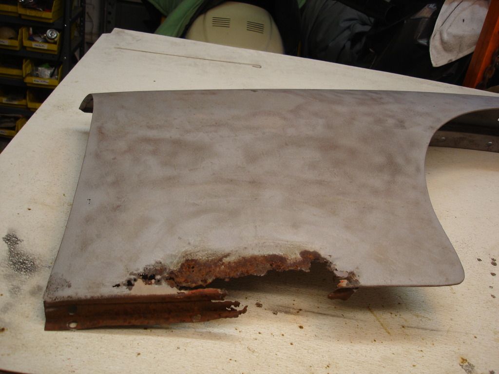
This week was dedicated to beginning the right wing. Once again, no breaks for the weary. This one is even worse than the left side.
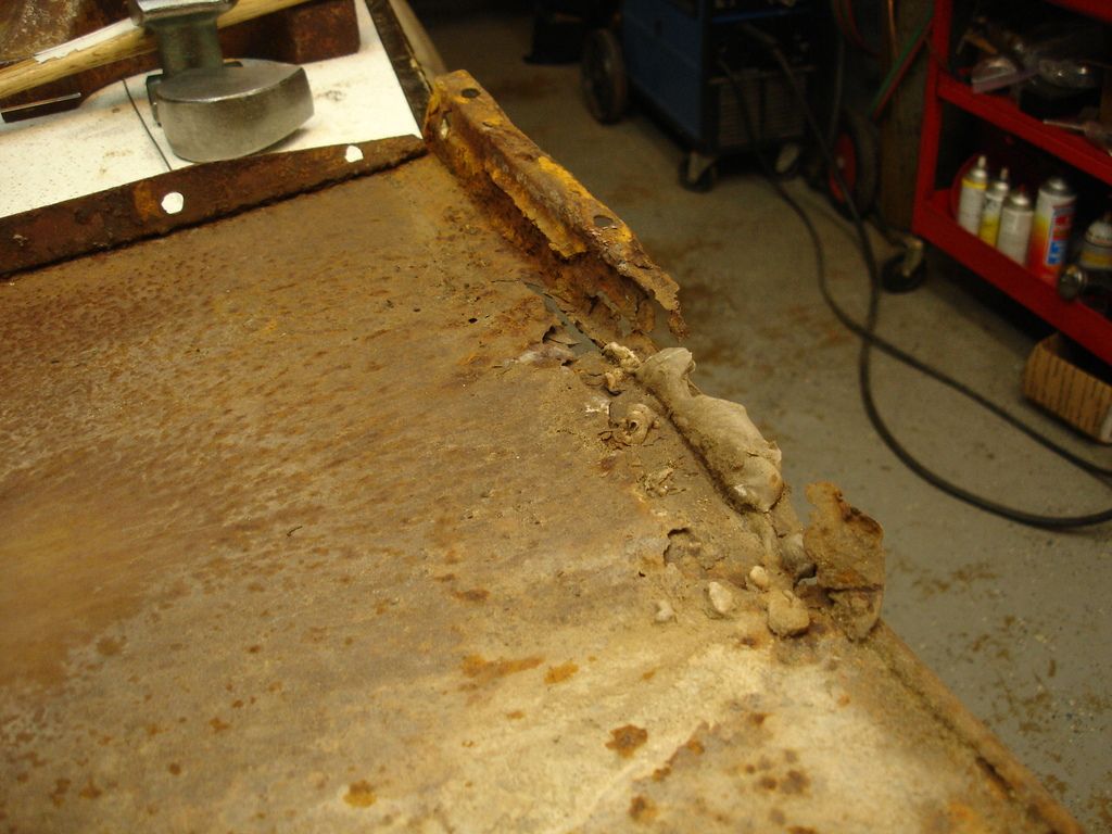
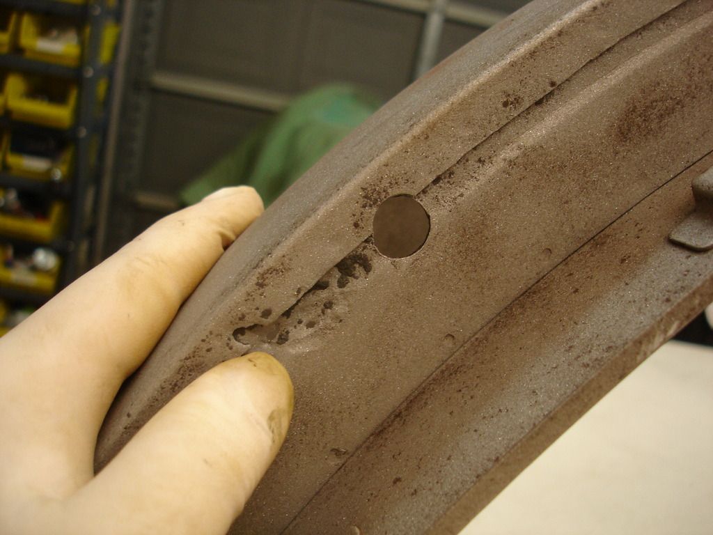
This is the inside of the lower area of the right wing. Lots of bondo shoved through rust holes. The lower mounting flange is half gone, and the rear one is not great either. The mounting hole to the farthest right in pic was drilled by the PO. Not sure what for??
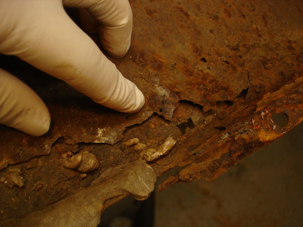
Close up of the "missing" metal. Nothing but bondo holding this puppy together.
View of the outside of this area. Anytime bondo is cracking, it's a sure sign it's ugly underneath.

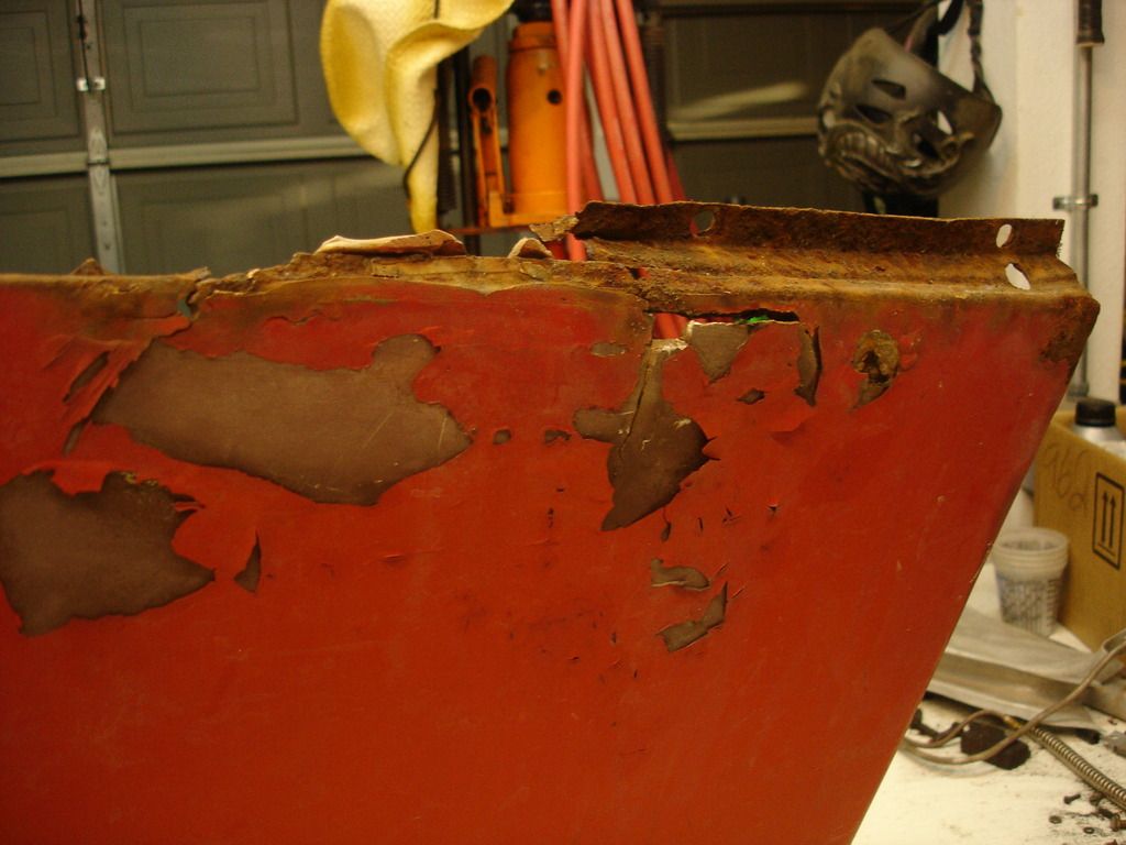
This rust is showing through on the very top of the wing, in the area that meets the scuttle and bonnet. This is not normally a rust-prone region, so I have no idea what the story is on this rust.
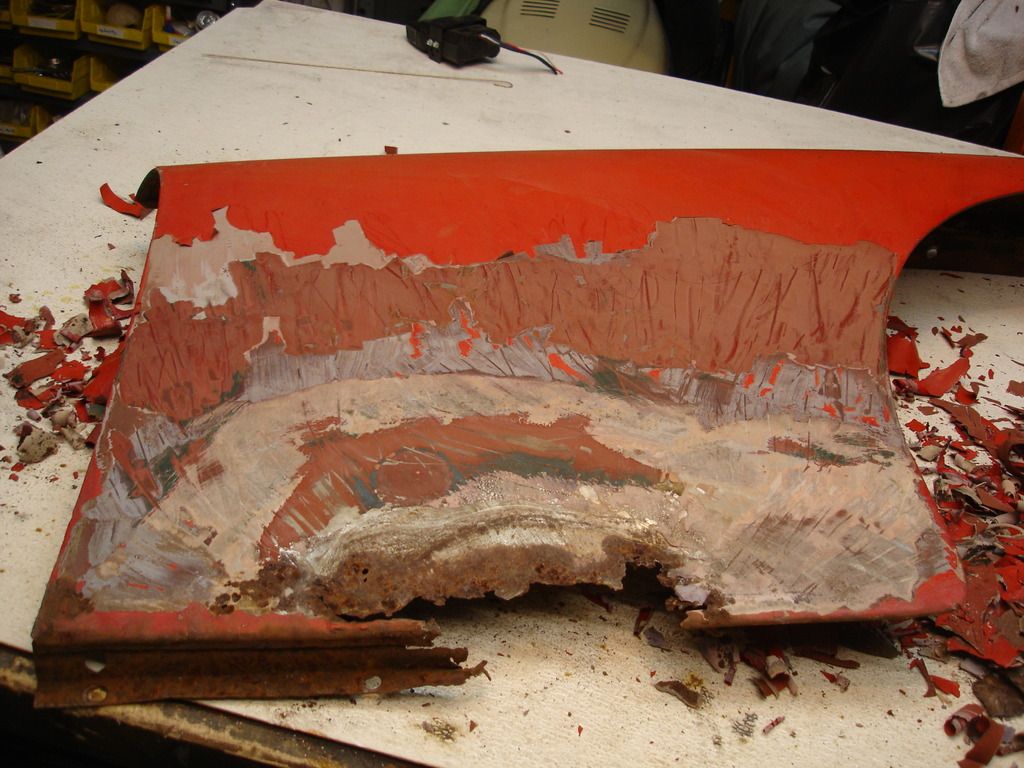
Getting to work. This is the wing after hitting it with mild heat from a torch and scraping all the putty off. 3 layers of paint and 2 of bondo.
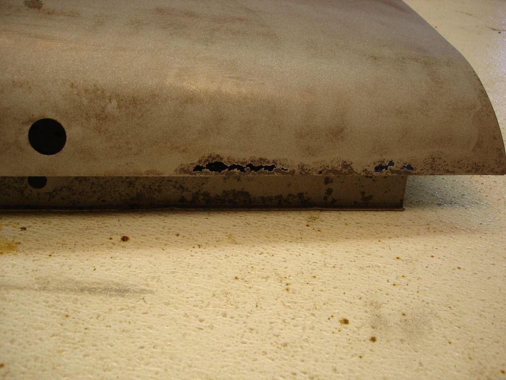
And...after a quick trip to the backyard for sand blasting, we're down to the basics. Of course, the lower section is going to have to come off...
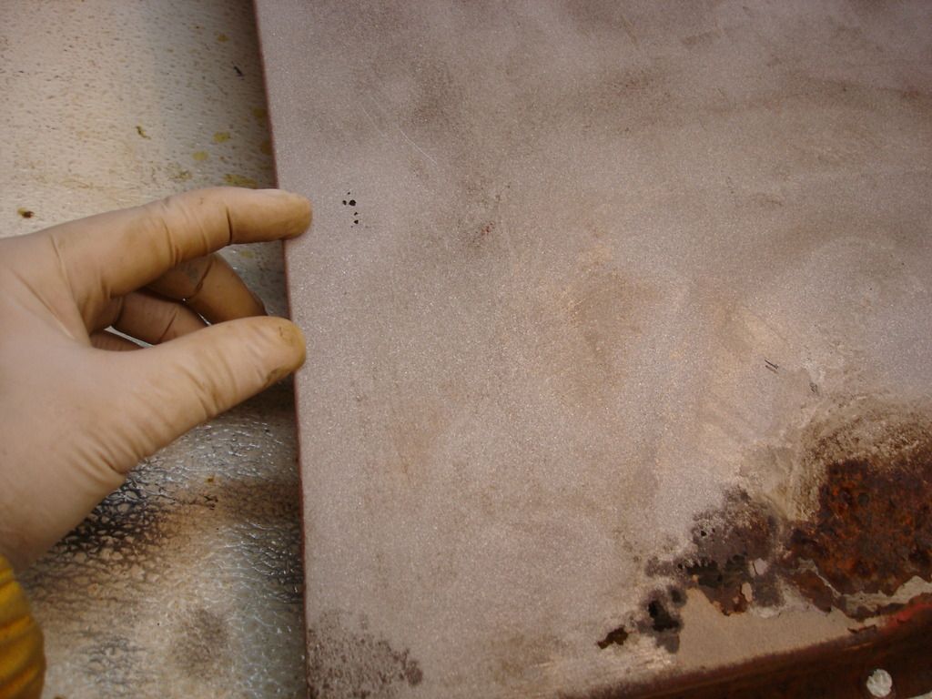

These pin-holes opened up with the blasting. They are up along the rear edge of the panel where it meets the front of the door. I will have to plan the patch metal to be large enough to remove this area too...
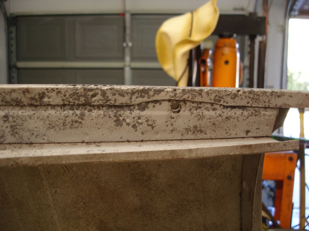
...and...the top of the wing where it meets the scuttle. Bummer! But, I actually like working on this area more than the large flat areas. The curvature prevents major warpage that has to be hammered out.
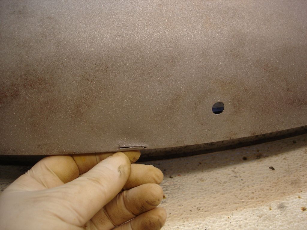
Farther forward, another one of those blasted 1/2" holes the PO put in just to annoy me! Also a small slice along the edge of the wing.
Along the upper mounting flange, there are a handful of pin-holes to be filled or patched.
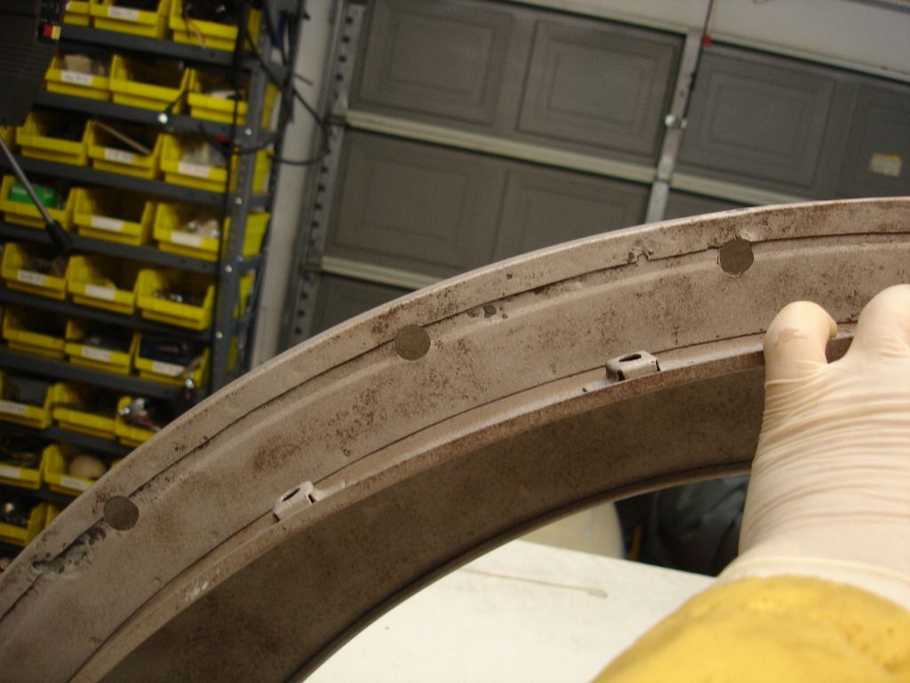
Of interest in this pic...this wing is an original TR2 wing. It is different than the TR3 wings in a couple ways. One is that the front apron mounting holes on the TR2 do not have slots, but only round holes to mount the apron. Secondly, if you notice in this pic, there is a groove that runs along the upper mounting flange on this TR2 wing. The TR3 does not have that notched groove. The slotted holes are mostly hidden in the wheel well, but the flange groove is noticeable any time the bonnet is open...to those few souls that would know to look. I wish I had noticed this when I had the flange removed from the left wing, as I could have easily added the TR2 groove. Oh well. I have to limit my annul tendency or I'll never finish this project!
The rear upper flange area. Not easy to see, but there are some pin-holes here to be filled.
I think that about wraps up the problems to be fixed. So time to get to work!
This week was dedicated to beginning the right wing. Once again, no breaks for the weary. This one is even worse than the left side.

This is the inside of the lower area of the right wing. Lots of bondo shoved through rust holes. The lower mounting flange is half gone, and the rear one is not great either. The mounting hole to the farthest right in pic was drilled by the PO. Not sure what for??

Close up of the "missing" metal. Nothing but bondo holding this puppy together.

View of the outside of this area. Anytime bondo is cracking, it's a sure sign it's ugly underneath.

This rust is showing through on the very top of the wing, in the area that meets the scuttle and bonnet. This is not normally a rust-prone region, so I have no idea what the story is on this rust.

Getting to work. This is the wing after hitting it with mild heat from a torch and scraping all the putty off. 3 layers of paint and 2 of bondo.

And...after a quick trip to the backyard for sand blasting, we're down to the basics. Of course, the lower section is going to have to come off...


These pin-holes opened up with the blasting. They are up along the rear edge of the panel where it meets the front of the door. I will have to plan the patch metal to be large enough to remove this area too...

...and...the top of the wing where it meets the scuttle. Bummer! But, I actually like working on this area more than the large flat areas. The curvature prevents major warpage that has to be hammered out.

Farther forward, another one of those blasted 1/2" holes the PO put in just to annoy me! Also a small slice along the edge of the wing.

Along the upper mounting flange, there are a handful of pin-holes to be filled or patched.

Of interest in this pic...this wing is an original TR2 wing. It is different than the TR3 wings in a couple ways. One is that the front apron mounting holes on the TR2 do not have slots, but only round holes to mount the apron. Secondly, if you notice in this pic, there is a groove that runs along the upper mounting flange on this TR2 wing. The TR3 does not have that notched groove. The slotted holes are mostly hidden in the wheel well, but the flange groove is noticeable any time the bonnet is open...to those few souls that would know to look. I wish I had noticed this when I had the flange removed from the left wing, as I could have easily added the TR2 groove. Oh well. I have to limit my annul tendency or I'll never finish this project!

The rear upper flange area. Not easy to see, but there are some pin-holes here to be filled.
I think that about wraps up the problems to be fixed. So time to get to work!
OP
CJD
Yoda
Offline

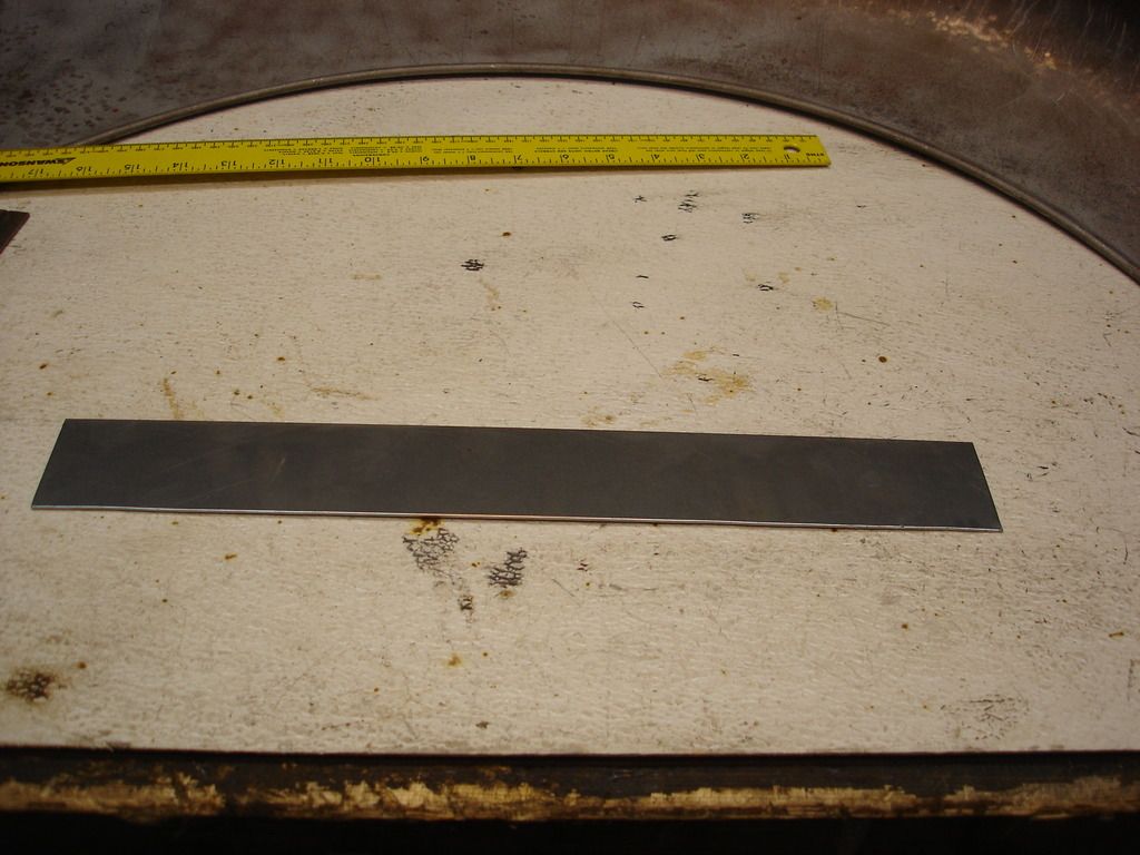
I have finally reached a point where I need more replacement metal than I can salvage from the bad body panels. I had to make a trip to the local steel supply.
A word on the metal used in TR2/3's. As I mentioned before, the metal on these cars is neither 18 nor 20 gage, but about mid-way between the 2 sizes. I bought 2' X 2' sections of both 18 and 20 gage cold rolled steel. I will use the 20 gage for panels that have to be worked a lot (i.e. patch panels), and the thicker 18 gage on the mounting flanges. So, in this pic I selected one of my new, $15, 20 gage sheets to become the patch.

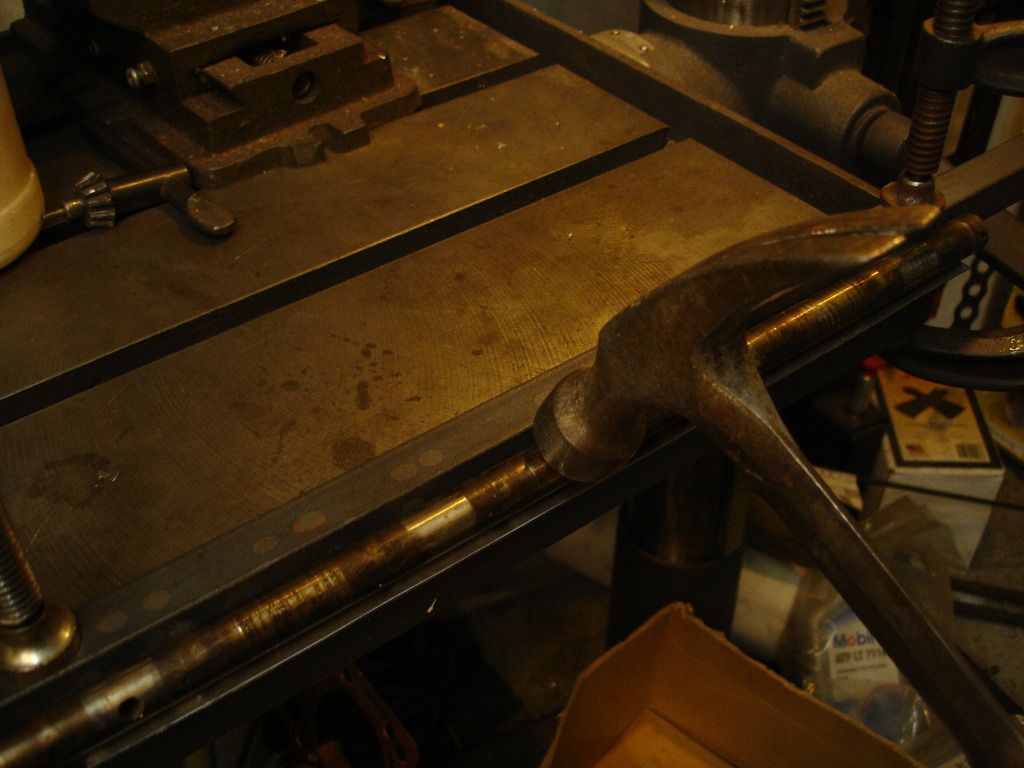
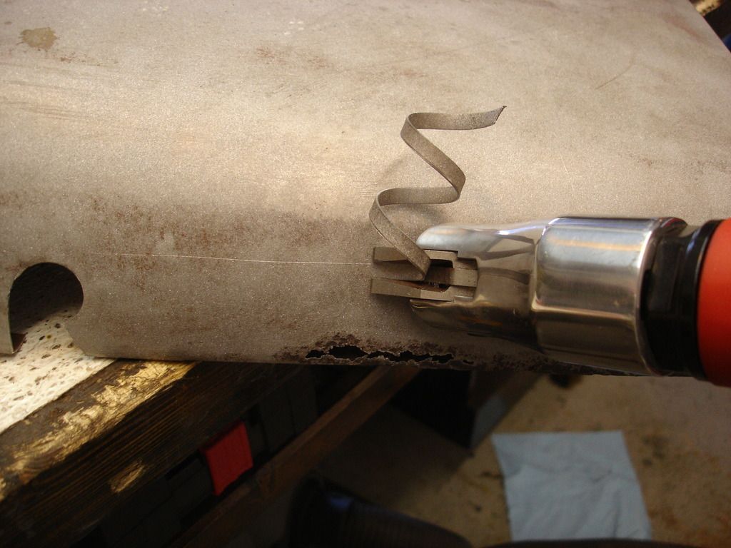
Once again the rear mounting flange has to come off to access the back side of the wing for repair. 4 tack welds from the factory have to be ground off.

Tush mentioned he had trouble removing his rear flange...and I experienced the same trouble with this wing. The issue is that the flange is so flimsy that it bends about like aluminum foil, so hitting it only distorts it. To keep it from distorting while I hit, I used a set of sheet-metal vise grips. In the pic I have gripped the flange as low down to the base as possible, and then whack away on the vise grips. This transfers the energy to the seem and minimizes distortion.


Bad pic, but I am trying to show the rust holes through the rear bracket. This will be an issue later, as I do not have a decent spare bracket to use like last time. The donor car right wing was so bad I just tossed it on the scrap pile...not a single area re-usable. The issue with this bracket is that it has a double curve to it, as it matches the curvature of the A-pillar on one edge, and the wing curvature on the other. This will be a problem for later, though.
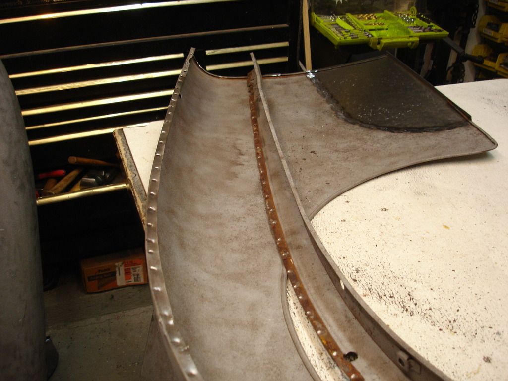
The following series is repetitious, so I'll let the photos speak for themselves. The patch went in exactly like the one on the left wing...


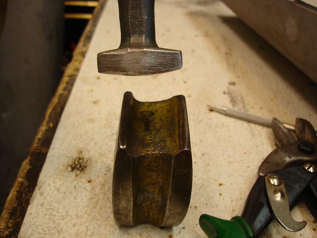
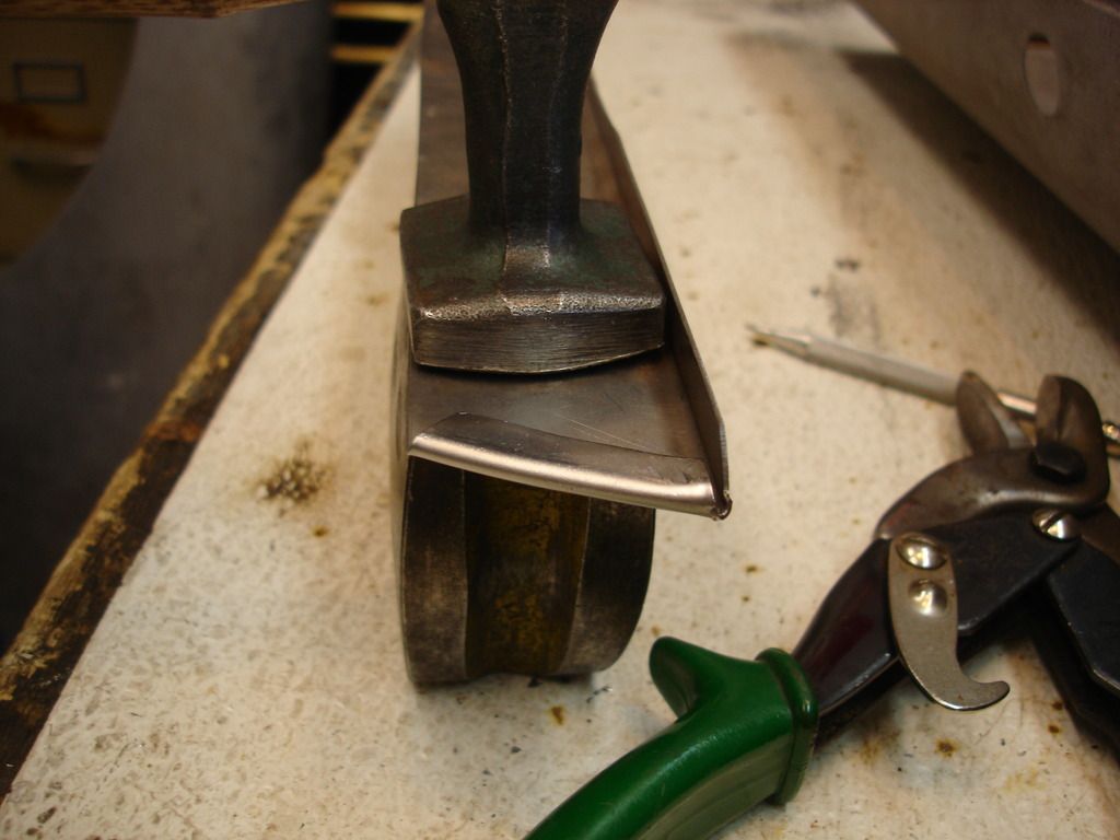
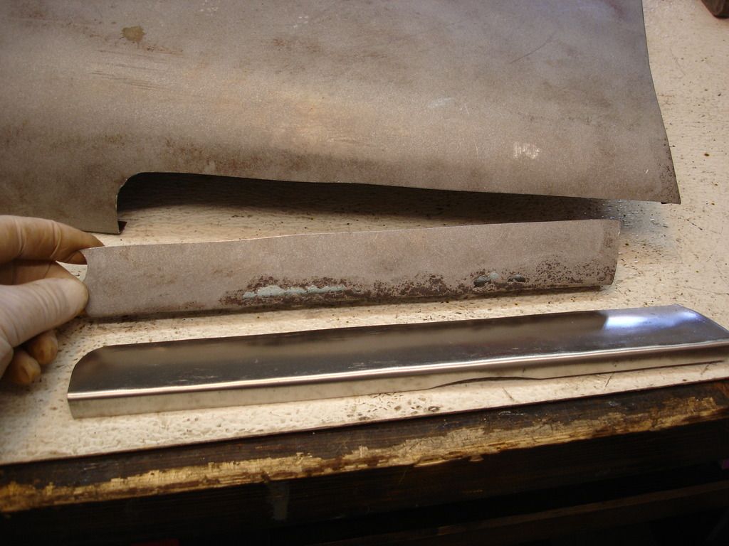
The rear edge has a curve to it...so the original curve is etched onto the new panel.

And the lip is folded over the etched curve. Note that I am using a bar of .080" steel to keep the fold open as I work it flat. This is the lip that holds the rear mounting flange in place.


Here, the original reinforcing wire is rusted away, so I will have to extend it with new wire.

Like so.

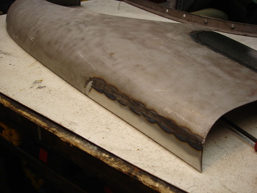
And this is where the week ended. The patch is in and ground flush. I still need to wrap the reinforcing wire and fashion a new lower mounting bracket.
Until next week!
M_Pied_Lourd
Darth Vader
Offline
Super helpful!
Cheers
Tush
Cheers
Tush
SteveBones
Jedi Trainee
Offline
 I second that - Helpful and interesting.
 Super helpful!
Cheers
Tush
M_Pied_Lourd
Darth Vader
Offline
Thanks John,
I've had to put my front fender reconstruction project on hold probably until spring as I need to drag the body out from beside the house where it is stored for the winter in order to check for fitment before I patch/weld anything.
Cheers
Tush
I've had to put my front fender reconstruction project on hold probably until spring as I need to drag the body out from beside the house where it is stored for the winter in order to check for fitment before I patch/weld anything.
Cheers
Tush
OP
CJD
Yoda
Offline
Tush, I would imagine you have to dig a bit of snow to get the tub out! I assume you guys got some of the record snow last week.
Week 19 (.5)
Got side-tracked with getting the kids licensed to drive for most of the week (another can of worms on another thread), but, I'm finally back to work. This week was dedicated to fashioning a new lower mounting bracket for the right wing. I will go into a lot of (boring) detail, in hope that the details will help others whose brackets have rusted away, like mine did. Fortunately, I have the TR3 sitting in the garage to take measurements from...but I assume not every hobbyist will have an extra car sitting around.
For starters, this job would have been easier had I thought to fashion both the left and right at the same time. I missed the ball on that one, so had to re-tool all over for the right bracket. They are identical, mirror images of each other.
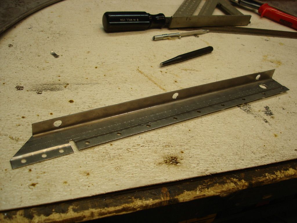
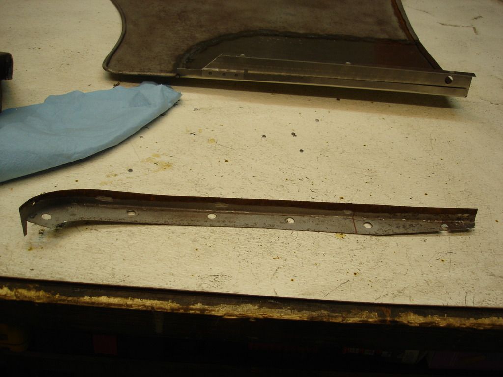
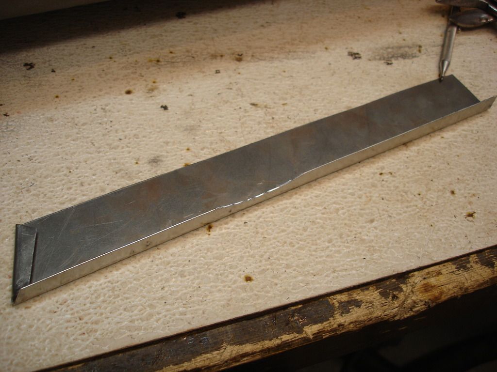
The beginning. Here is a strip of 18 gage cold rolled steel ready to go. For the other bracket I used re-cycled material from an old door...only important to have a decent straight section between 18 and 20 gage.
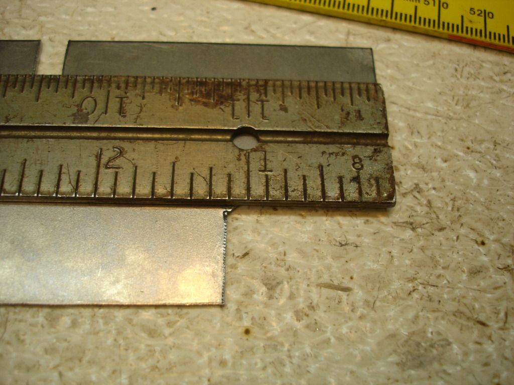
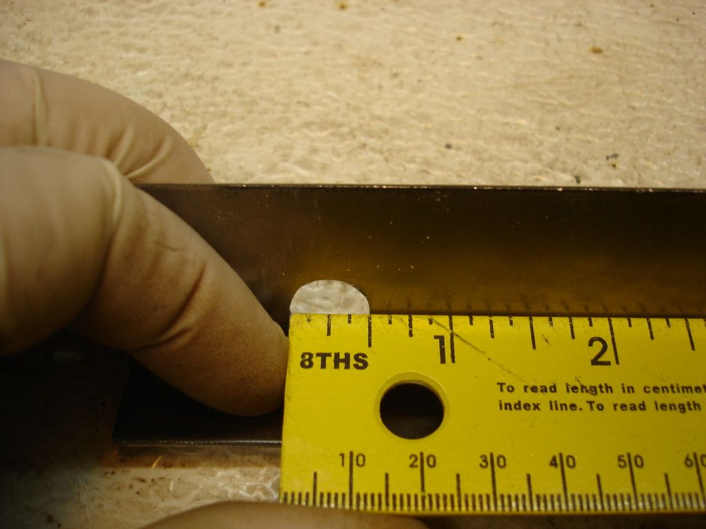
The forward end gets notched to the measurements shown here. At this point both left and right brackets are still identical.
Right at the corner of the notch, you will need a line scribed down the length of the bracket. This will be the bend point later...for now just scribe it.
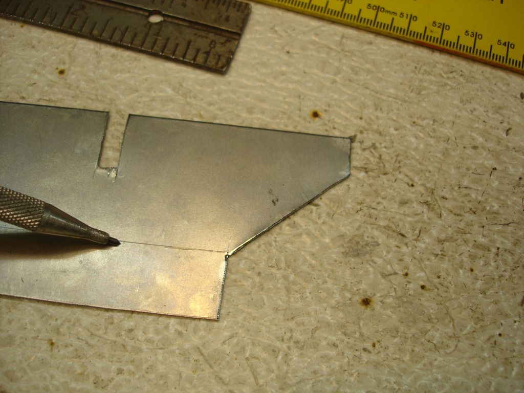
The brackets both get notched as shown...still identical so far.
At this point the left and right bracket fabbing diverges. One gets bent in one direction, and the other is bent opposite. If you do them as a pair, it's a no-brainer. If you are only fabbing one, be sure to bend it in the correct direction for the side you need.
Week 19 (.5)
Got side-tracked with getting the kids licensed to drive for most of the week (another can of worms on another thread), but, I'm finally back to work. This week was dedicated to fashioning a new lower mounting bracket for the right wing. I will go into a lot of (boring) detail, in hope that the details will help others whose brackets have rusted away, like mine did. Fortunately, I have the TR3 sitting in the garage to take measurements from...but I assume not every hobbyist will have an extra car sitting around.
For starters, this job would have been easier had I thought to fashion both the left and right at the same time. I missed the ball on that one, so had to re-tool all over for the right bracket. They are identical, mirror images of each other.


The beginning. Here is a strip of 18 gage cold rolled steel ready to go. For the other bracket I used re-cycled material from an old door...only important to have a decent straight section between 18 and 20 gage.


The forward end gets notched to the measurements shown here. At this point both left and right brackets are still identical.

Right at the corner of the notch, you will need a line scribed down the length of the bracket. This will be the bend point later...for now just scribe it.


The brackets both get notched as shown...still identical so far.
At this point the left and right bracket fabbing diverges. One gets bent in one direction, and the other is bent opposite. If you do them as a pair, it's a no-brainer. If you are only fabbing one, be sure to bend it in the correct direction for the side you need.
OP
CJD
Yoda
Offline
It's now time to branch out into a left or right bracket. From here on we have to pay attention to make sure we don't accidentally make the wrong side...not saying that I have ever done that...(but unable to confirm that I haven't).
The next step is where a bending brake would be a marvelous tool to have. We are simply going to bend the brackets at the line we scribed. Put all your cups down now, and try not to laugh too hard at my "poor man's" brake...don't want you to have to clean up from blowing your drink out of your nose laughing.
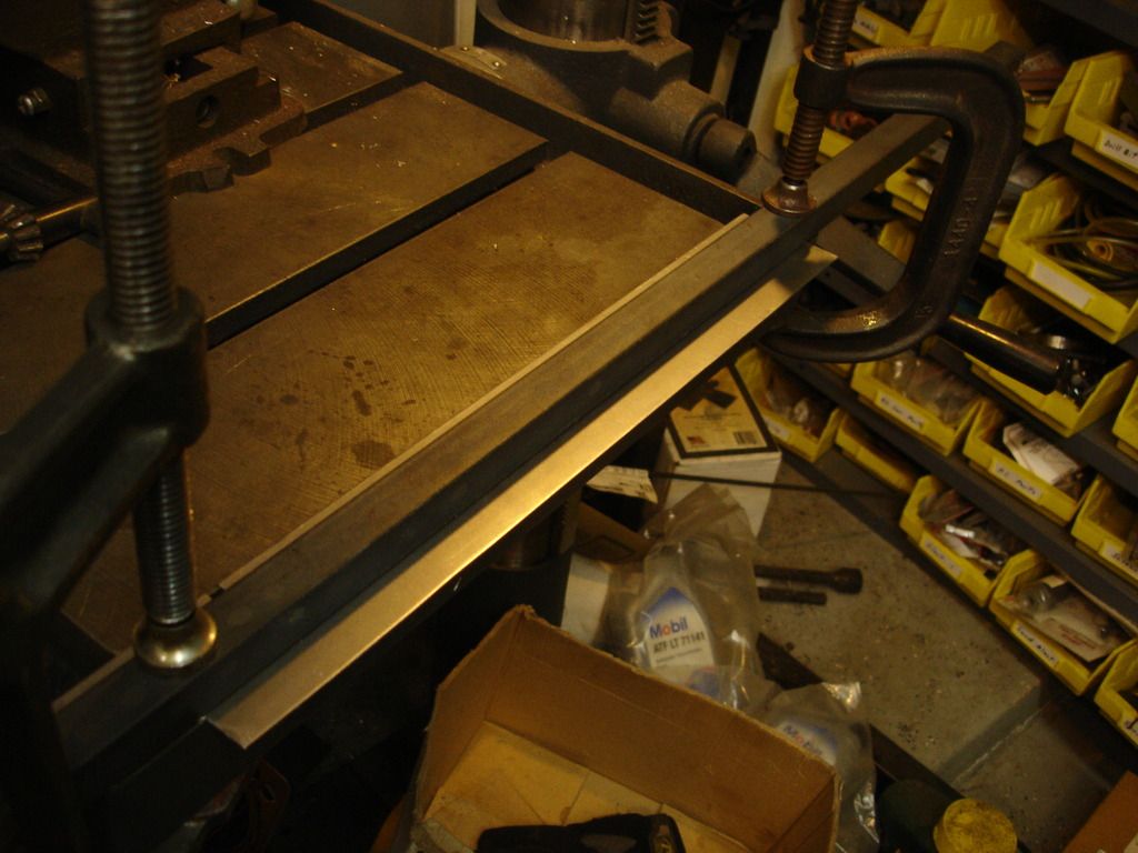
Yes...this is my drill press with a length of re-bar clamped over the bracket.
Common...I asked you not to laugh so hard!
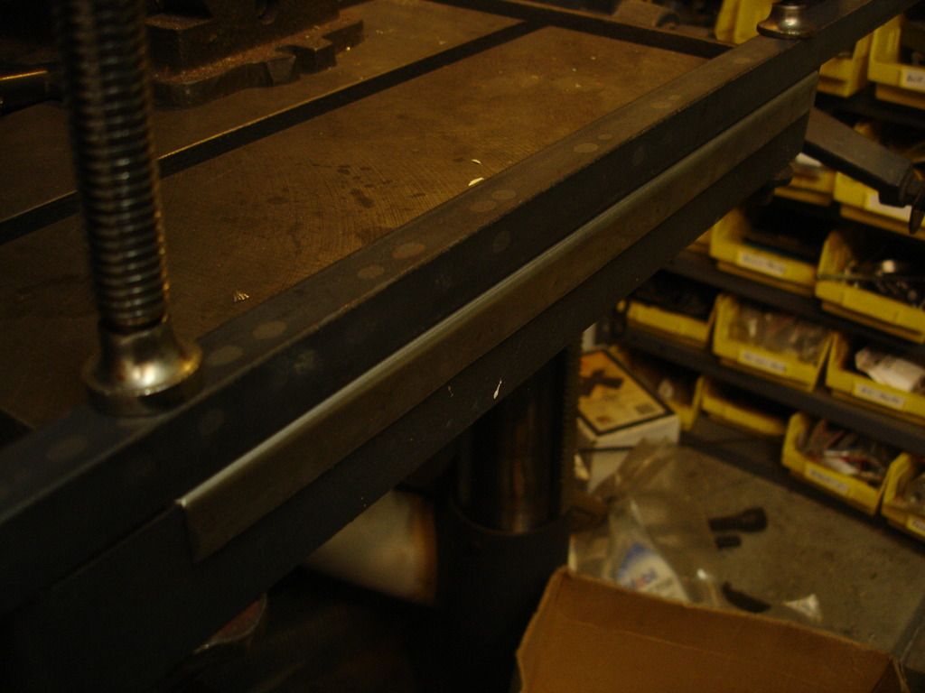
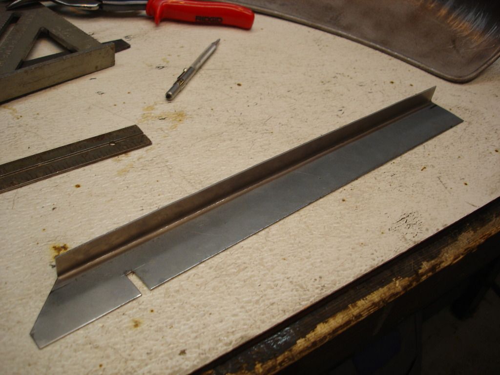
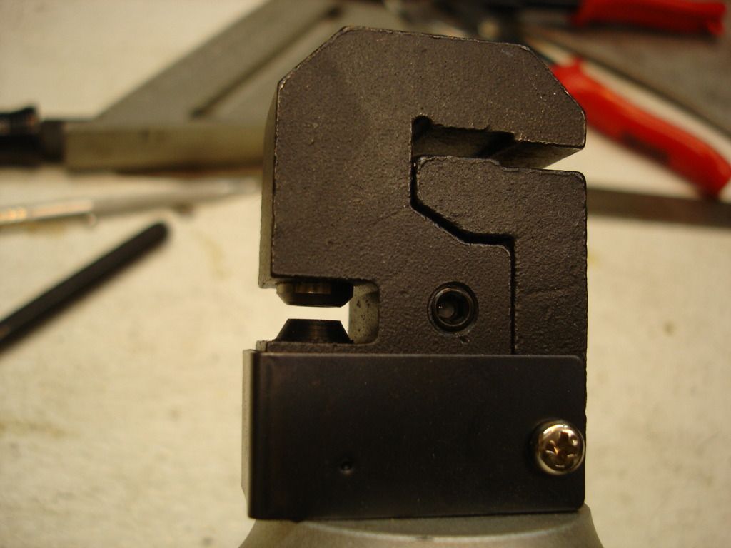
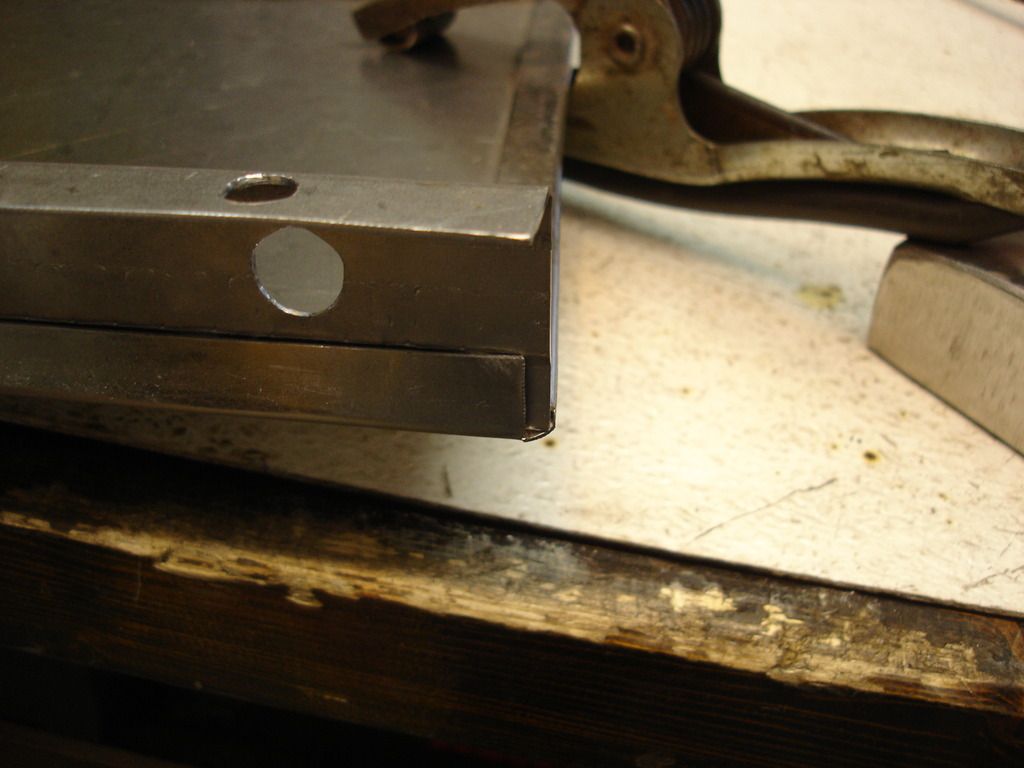
So, assuming everyone is cleaned up, here is where we are so far. This is the direction of bend for the right bracket. It is bent just short of 90 degrees...like about 85 degrees I'd say.
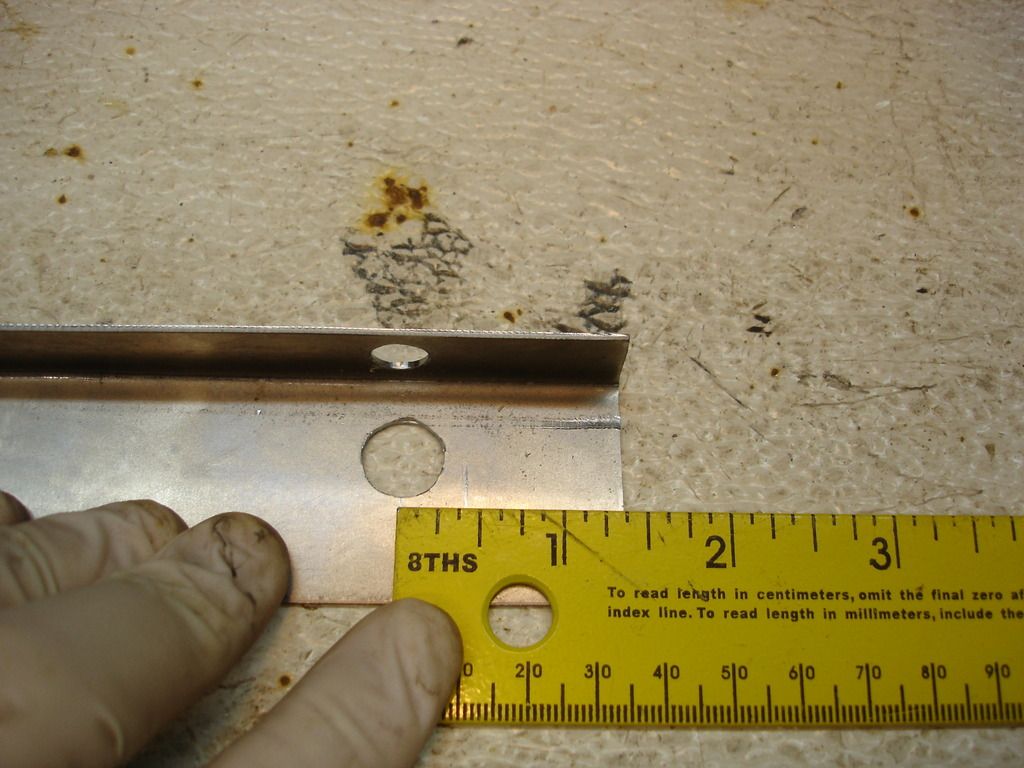

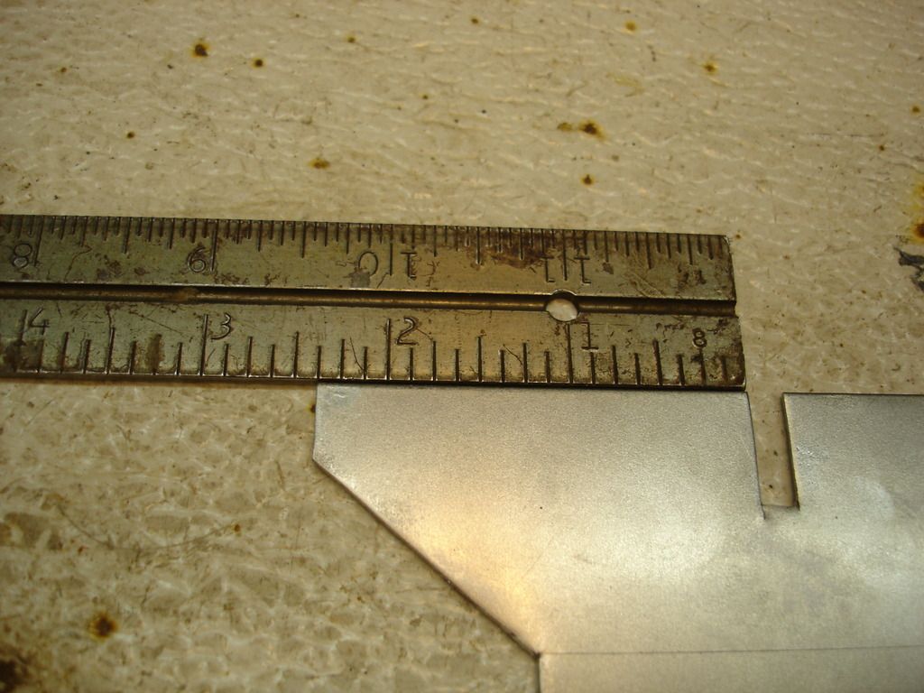
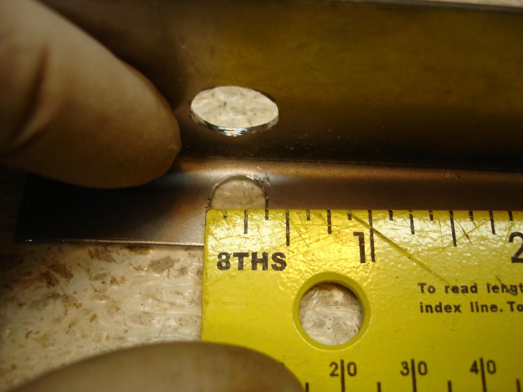
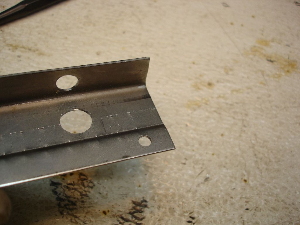
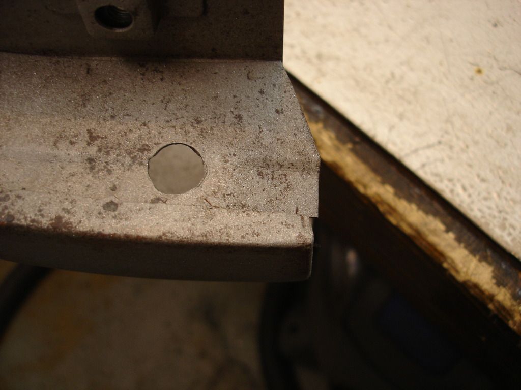
This is the location and size of the larger water drain hole.
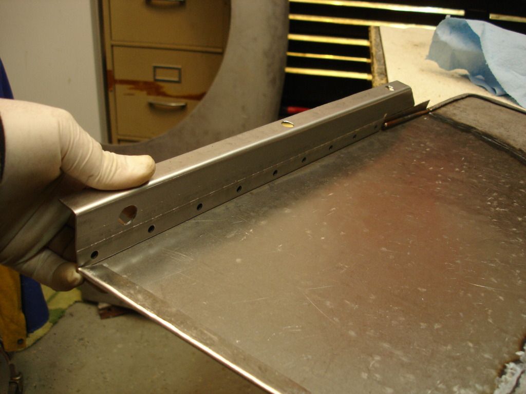
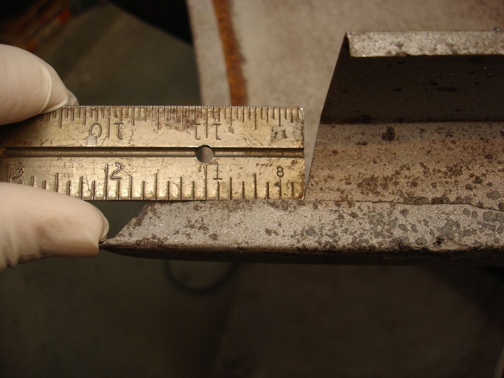
There are 3 mounting holes, used to attach the bracket to the inner sill. They are sized and spaced here...
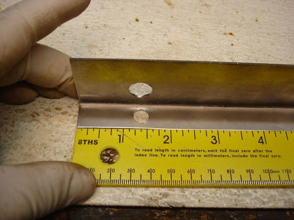
I warned you guys this was going to be boring...well...except for my bending brake.
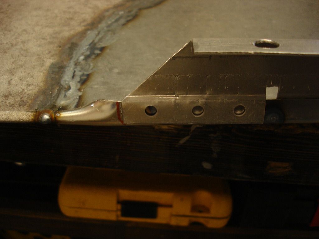
Here is my new $40 Northern crimping tool. I knew this baby would come in handy for many projects. You can do without it, by laying the bracket under/and over 2 steel plates and hammering down on the sandwich to shape the crimp. Tricky, but doable. I'd demonstrate THAT technique...but assume you've replaced your coffee and don't want you to loose it so soon after freshening the cup.
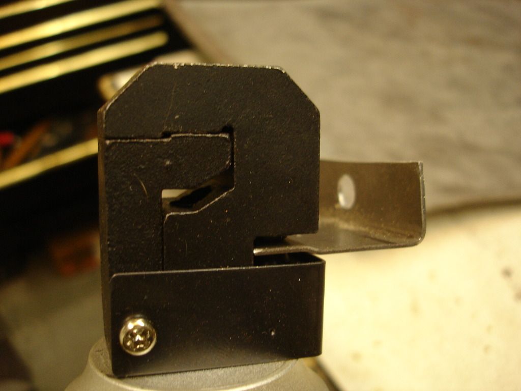
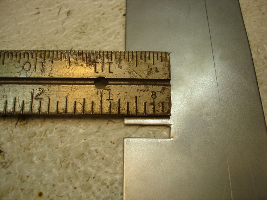
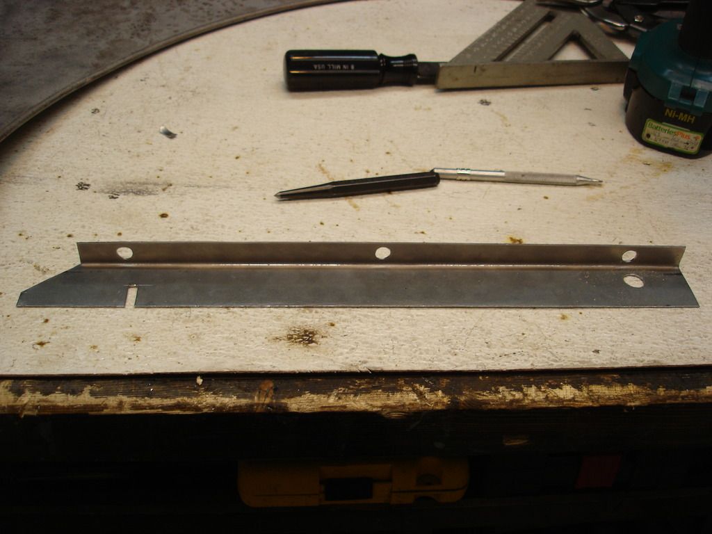
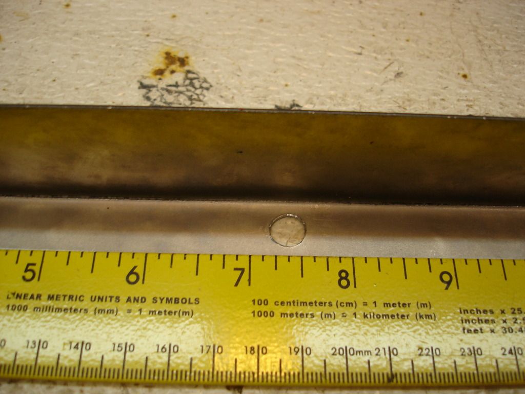
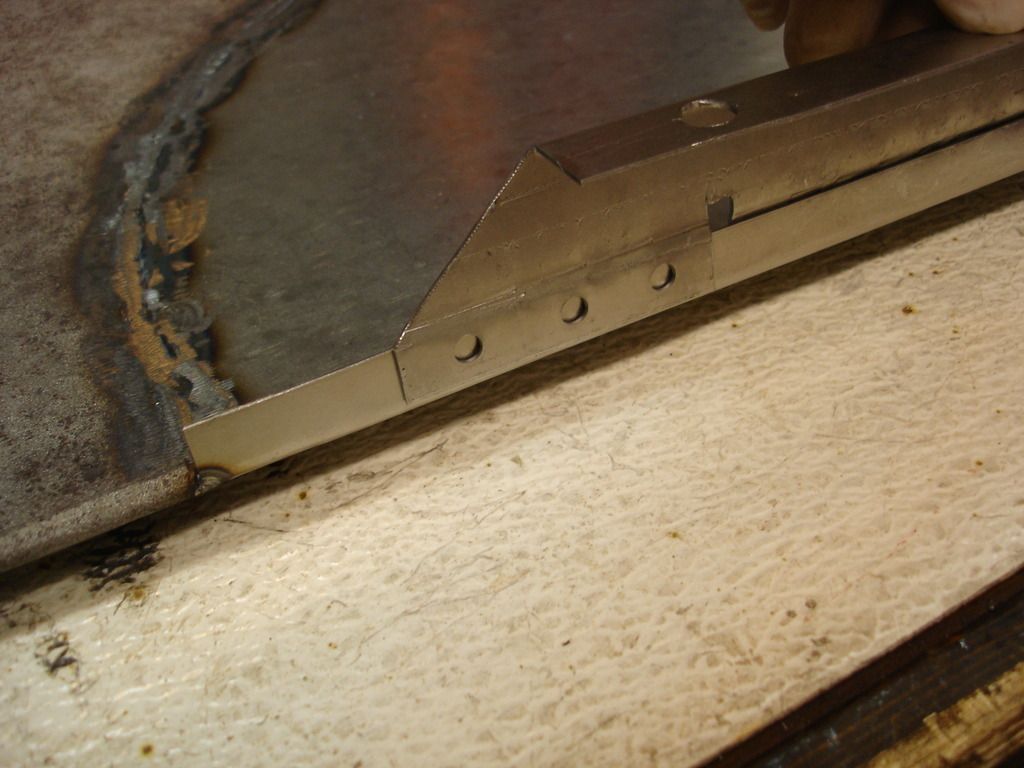
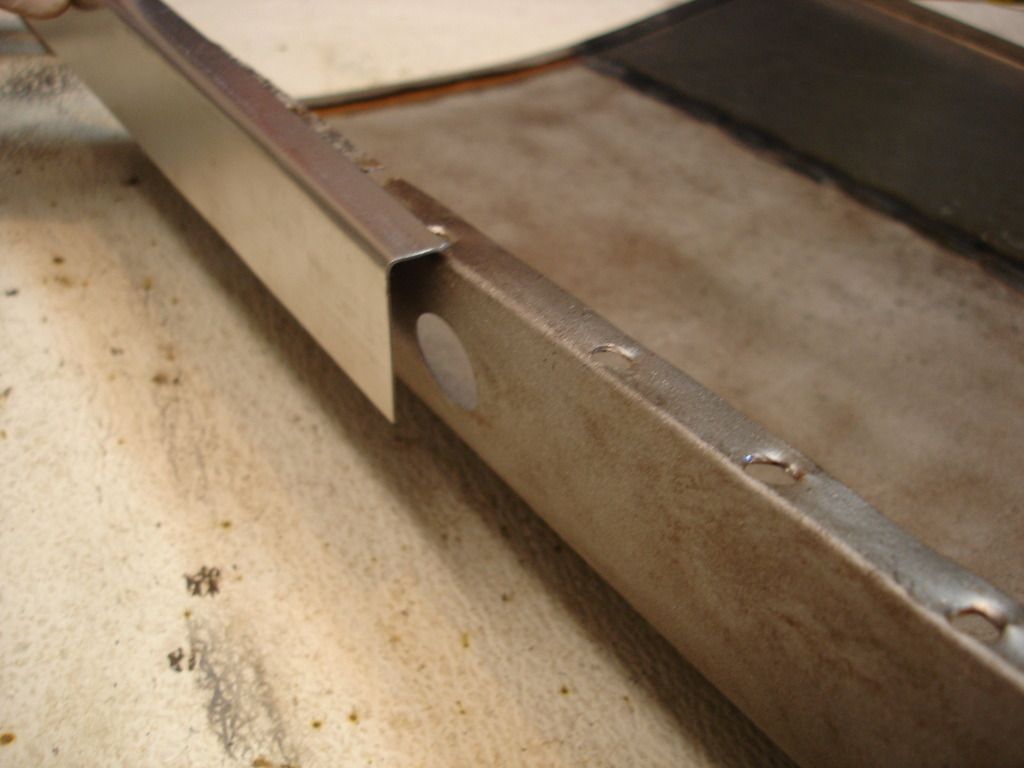
Here is the tool in action. It just pneumatically "pinches" a crimp into the edge of the bracket. Note the direction of crimp is towards the angle we bent...for the long rear section.
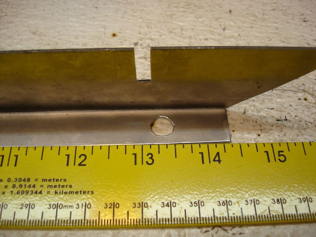
And the small section in front of the notch gets crimped AWAY from the angle.
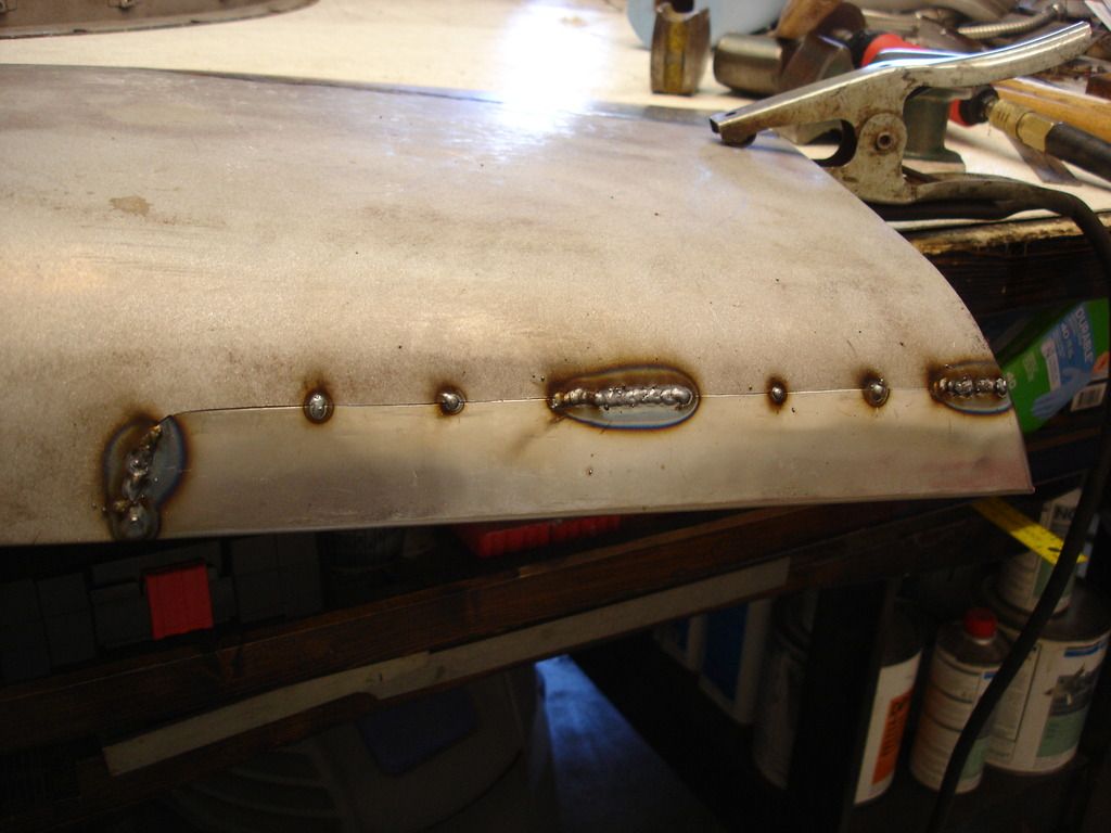
Notice also that I punched a string of random holes along the crimped edge (back side of the same tool...told you it would come in handy!). These are where I will hole weld the bracket to the wing, simulating spot welds. Speaking of which...hole welding is also the "poor man's" way of spot welding. If you are lucky enough to own a REAL spot welder, ship it to me at: John DuR.....
Oops, sorry, I meant that you will not have to punch the holes if you are able to spot weld the bracket, THEN ship the spot welder to me....!
The next step is where a bending brake would be a marvelous tool to have. We are simply going to bend the brackets at the line we scribed. Put all your cups down now, and try not to laugh too hard at my "poor man's" brake...don't want you to have to clean up from blowing your drink out of your nose laughing.

Yes...this is my drill press with a length of re-bar clamped over the bracket.
Common...I asked you not to laugh so hard!


So, assuming everyone is cleaned up, here is where we are so far. This is the direction of bend for the right bracket. It is bent just short of 90 degrees...like about 85 degrees I'd say.


This is the location and size of the larger water drain hole.
There are 3 mounting holes, used to attach the bracket to the inner sill. They are sized and spaced here...


I warned you guys this was going to be boring...well...except for my bending brake.

Here is my new $40 Northern crimping tool. I knew this baby would come in handy for many projects. You can do without it, by laying the bracket under/and over 2 steel plates and hammering down on the sandwich to shape the crimp. Tricky, but doable. I'd demonstrate THAT technique...but assume you've replaced your coffee and don't want you to loose it so soon after freshening the cup.


Here is the tool in action. It just pneumatically "pinches" a crimp into the edge of the bracket. Note the direction of crimp is towards the angle we bent...for the long rear section.

And the small section in front of the notch gets crimped AWAY from the angle.
Notice also that I punched a string of random holes along the crimped edge (back side of the same tool...told you it would come in handy!). These are where I will hole weld the bracket to the wing, simulating spot welds. Speaking of which...hole welding is also the "poor man's" way of spot welding. If you are lucky enough to own a REAL spot welder, ship it to me at: John DuR.....
Oops, sorry, I meant that you will not have to punch the holes if you are able to spot weld the bracket, THEN ship the spot welder to me....!
Last edited:
OP
CJD
Yoda
Offline


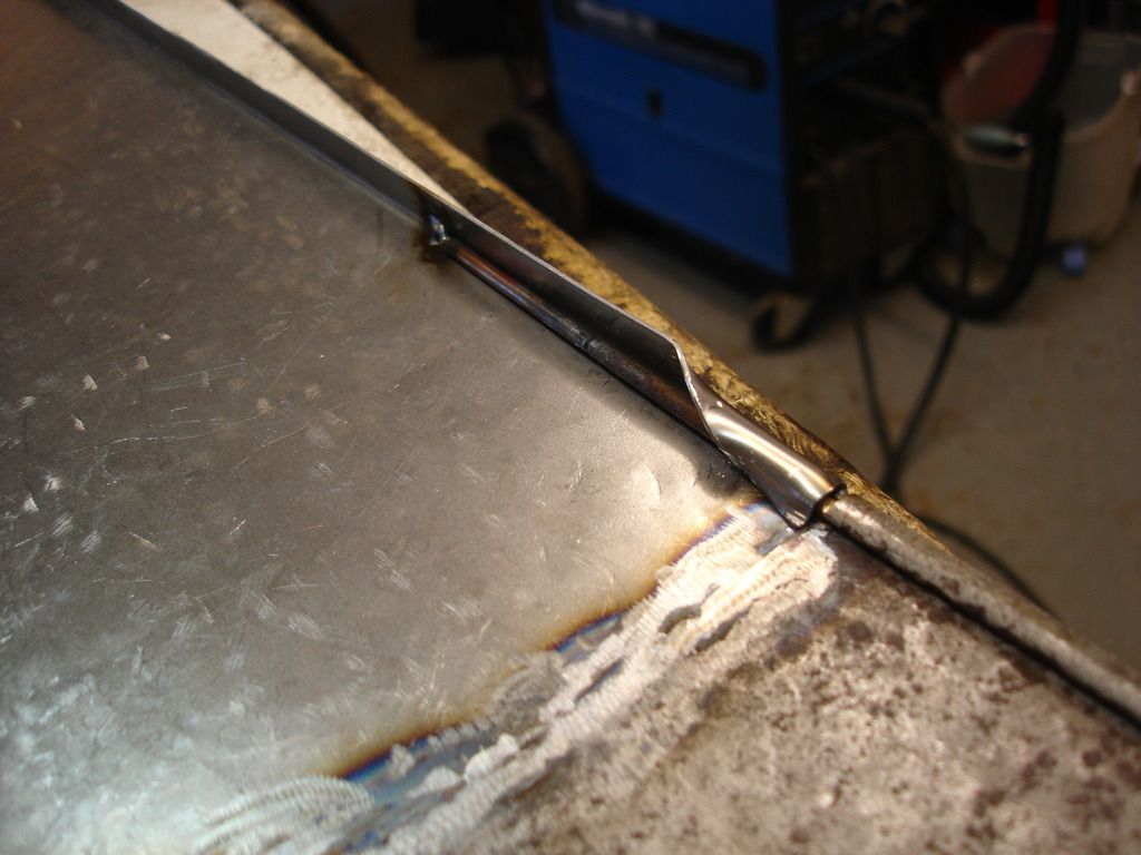
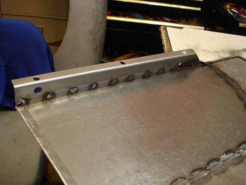
Here is our fresh, new, bracket held next to the one I fashioned a couple weeks ago and mounted on the left wing. You can see where I hole welded the bracket in place, and then ground the extra bead down flush. Guaranteed that once you are done and the car is painted, nobody will ever know it was home-made!
That's it for week 19. I know you're bummed for me at how little I got done...I know I am. But, there is always next...I mean THIS week!
Until then, I mean now, only later....
M_Pied_Lourd
Darth Vader
Offline
You got 100 per cent more than I got done ")
Excellent work!
Cheers
Tush
Excellent work!
Cheers
Tush
OP
CJD
Yoda
Offline
Week 20
I just figured out this is a leap year. That means one extra day to put towards the restoration that I wasn't counting on!
As I left you, we had fabbed a new lower mounting bracket for the wing. Now it's time to put it on the wing.
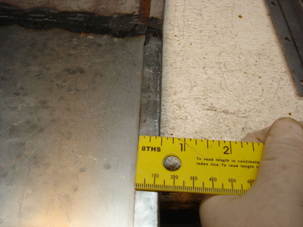
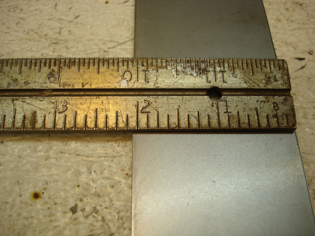
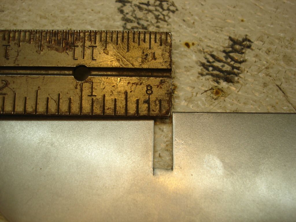
This is just a quick measurement to show the lip fold that retains the rear wing bracket. Might be helpful to others that make their own patch panel.
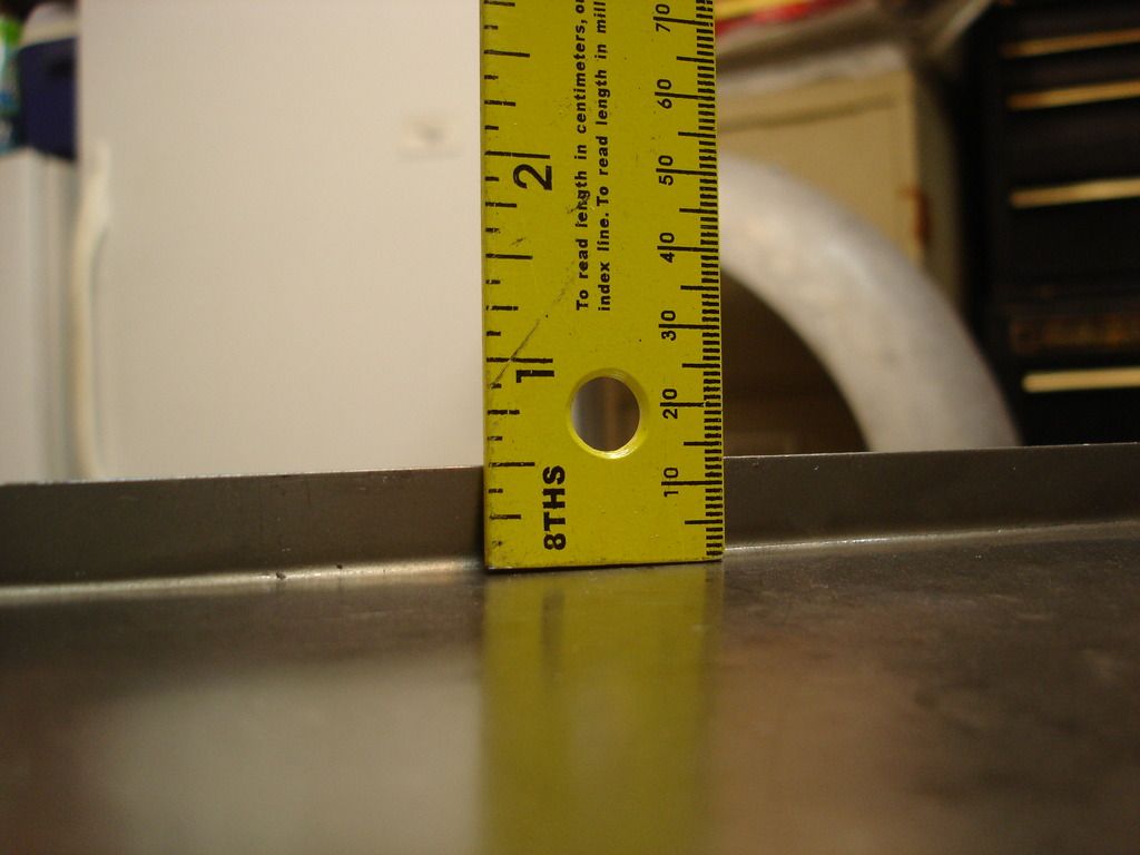
And here is the measurement for the lower lip on the wings.
A quick test fit for the new lower bracket we made on the wing.
This is the alignment for the bracket at the rear edge of the wing.
And, the front of the bracket goes here. The patch panel has to be folded over the reinforcement wire just in front of the bracket.
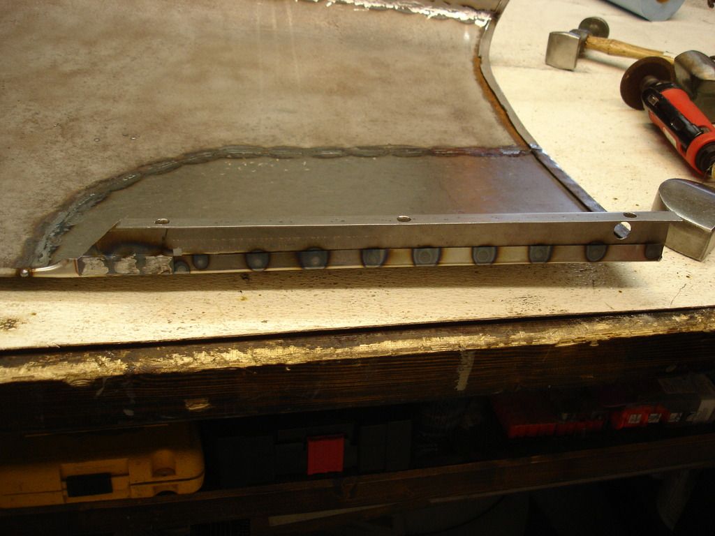
And the bracket gets hole-welded in place.
I just figured out this is a leap year. That means one extra day to put towards the restoration that I wasn't counting on!
As I left you, we had fabbed a new lower mounting bracket for the wing. Now it's time to put it on the wing.

This is just a quick measurement to show the lip fold that retains the rear wing bracket. Might be helpful to others that make their own patch panel.

And here is the measurement for the lower lip on the wings.


A quick test fit for the new lower bracket we made on the wing.

This is the alignment for the bracket at the rear edge of the wing.


And, the front of the bracket goes here. The patch panel has to be folded over the reinforcement wire just in front of the bracket.


And the bracket gets hole-welded in place.
OP
CJD
Yoda
Offline

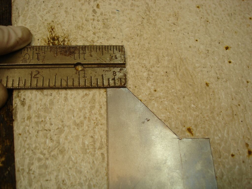
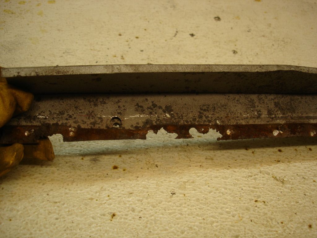
Now it's time to fix the rusted out portion of the rear bracket. Here I have marked the portion that has to be removed.

Notice that this bracket is bent on 2 planes, so the I made sure it fit the wing and door edges before I cut the piece off.


The photo sequence above shows the evolution of the patch that will replace the rusted section. This part gets fully shaped before I cut the bad metal off.

Now the bad metal has been removed, so time to align and weld the patch in place.

And the finished bracket.


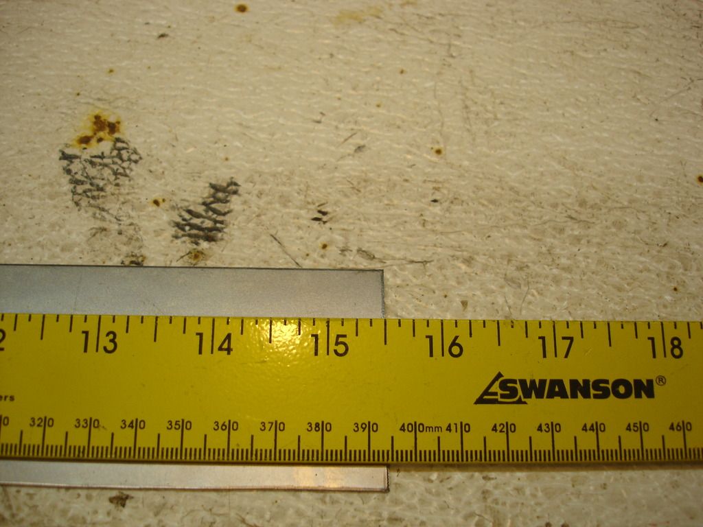
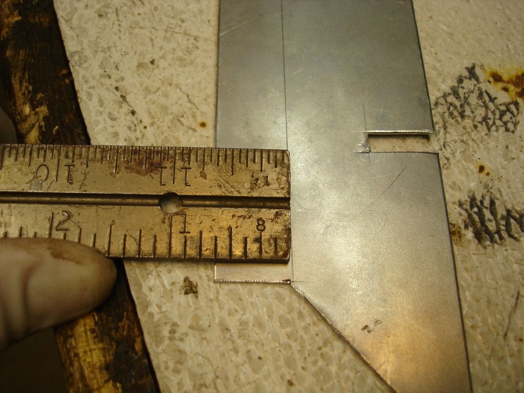
I measured that the bracket should be 7/8" back from the rear lip of the wing once it is installed.

Once the lip is hammered down over the bracket, the rear bracket gets tacked in place as the factory did it.
OP
CJD
Yoda
Offline
Now it's time for the rusted out section on the top of the right wing. I pondered this repair for a couple weeks, and finally decided the entire upper bracket should come off. This is just to get better access to both sides of the wing for the welding. So, here it goes.
Of course, I took measurements on the bracket, both front and rear to ensure I can reinstall it back in the proper location later.
An hour of spot weld drilling later, the bracket is off. I did notice that the earlier TR2 wings have more spot welds than the later TR3 wing. Another example of how older parts are better!
This is the area of the bracket that is rusted out. More patching...it's like it never ends!?!
This is the patch for the upper wing taking shape. This section takes a good bit of curvature, so I used the dolly and hammer in the pic to gradually work the curve into it.
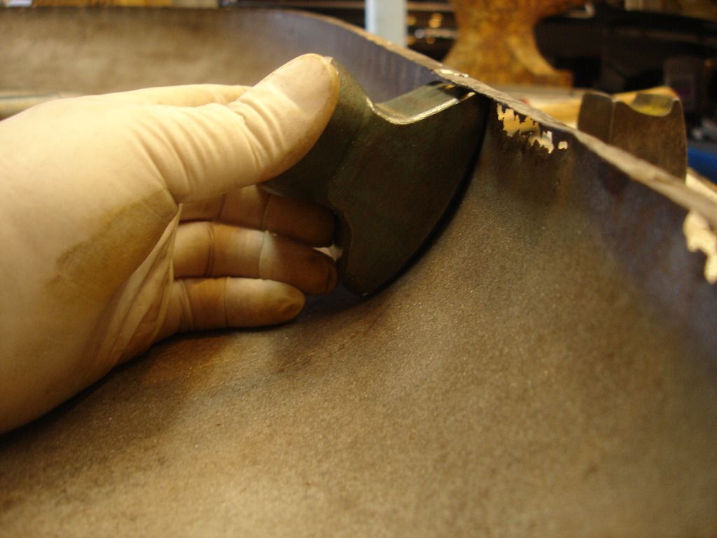
Before I cut the bad section out, I checked for the dolly that has the best fit. I'll need to know this to straighten the section after the welding.
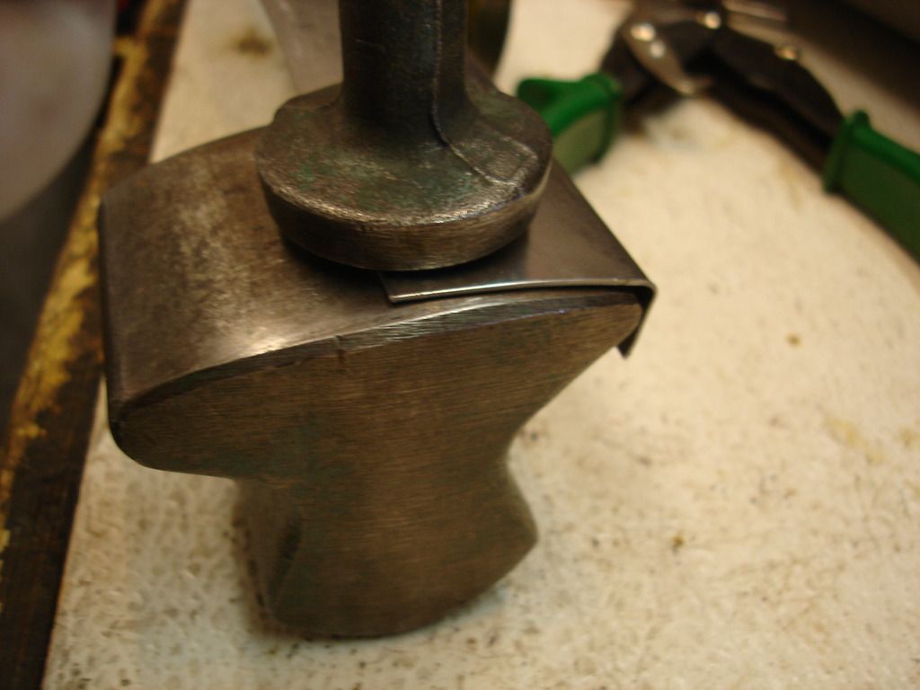
And here I am transferring the shape to the patch panel to get the final curvature perfect.
This sequence shows the patch going in. Of course it got ground and straightened after the final welding.


Of course, I took measurements on the bracket, both front and rear to ensure I can reinstall it back in the proper location later.

An hour of spot weld drilling later, the bracket is off. I did notice that the earlier TR2 wings have more spot welds than the later TR3 wing. Another example of how older parts are better!

This is the area of the bracket that is rusted out. More patching...it's like it never ends!?!


This is the patch for the upper wing taking shape. This section takes a good bit of curvature, so I used the dolly and hammer in the pic to gradually work the curve into it.

Before I cut the bad section out, I checked for the dolly that has the best fit. I'll need to know this to straighten the section after the welding.

And here I am transferring the shape to the patch panel to get the final curvature perfect.


This sequence shows the patch going in. Of course it got ground and straightened after the final welding.
Last edited:
OP
CJD
Yoda
Offline


This is the (other) annoying 1/2" hole, and the slit of unknown origin. They got patched and/or fill welded.

Now for the corrosion on the upper bracket.

The spot welds get drilled out to make room for the new patch.

And the old section comes off. For once I am working with a flat piece of metal, so all the forming isn't needed.

The cage and nut will get re-used. Anything to save a few cents!

I am using the good section of the wing patch as material for the bracket.


And the patch is in place. Notice there is a ridge in the bracket for the TR2. My fancy machine stamper didn't have enough reach to put that in...so I just laid the bracket patch on the anvil with a scrap of steel plate under it. I then hammered the ridge into it. Another example of time over tools.

Farther forward there was another rust-out that got a small patch.


Once again I am fitting the brakcet to the front apron to make sure it fits right. Of course it didn't! Notice I had to slice a couple places and then weld the slice closed to correct the curve to match the apron.


And it gets checked again after the wing is hole welded back onto the bracket.

This is a shot to show fixing another goof. The lower patch panel has almost no curvature at all. I added a good bit, and then welded it in place with this excessive curvature. When I realized the mistake, the metal had to be shrunk to get the curvature to straighten back out without oil-canning. It was a pain, but it does show how you cannot ruin a part...just keep working it until you are satisfied.


Once all the brackets are in place...I checked the wing to door fit. Close enough until the final fitting.


While checking the fit, I noticed a spot that was worn through on the door. A perfect example of how you can get too close to your work. I spent 3 weeks JUST on that door...and still missed this spot! You can never check too many times, and never try to rush body work. The time is an investment in the finished body.


I sand blasted the finished wing to relieve the stresses...and another panel goes back to the shed for final fitting.
I am down to only the rear wings...!
M_Pied_Lourd
Darth Vader
Offline
This is an awesome thread! Thanks John.
Cheers
Tush
Cheers
Tush
OP
CJD
Yoda
Offline
I think I can finally see the path to the end. I figure I can finish the rear wings in mid March, which marks about 50% of the total bodywork. So, starting the tub in March means painting in late summer. That would lead to a driving car about this time next year.
I'll need a break after this project. Perhaps a road trip up north...like Newmarket...
I'll need a break after this project. Perhaps a road trip up north...like Newmarket...