• Hi Guest!
    You can help ensure that British Car Forum (BCF) continues to provide a great place to engage in the British car hobby! If you find BCF a beneficial community, please consider supporting our efforts with a subscription.

    There are some perks with a member upgrade!
    **Upgrade Now**
    (PS: Subscribers don't see this gawd-aweful banner
Tips
Tips

TR2/3/3A Beginning the TR2 Bodywork


Before I fit the brace, I had to take care of the right end, which I was keeping, but had been pretty rusted out.


I took off the end cap with a cut-off disc.


Back to my old door skin, I cut out a replacement section, using the old brace cap to get the size right.


Sorry for the poor pics.
I don't own a bending break...although I could really use one. Until I move out of working in a garage, I don't have room for one anyway. But, here I am using a simple 6" table vise to bend the angles on the new end cap.


I tacked the new cap on, still to the rough size, and then ground the edges to shape.


I had to shape the brace for the final fitting. You can see the heat coloration where I had to place the brace back in my vice, heat the appropriate area with a torch, and tweek it to the proper contour.


This is the little insulating pad that goes under the brace and against the bonnet. It appears to be horse-hair, similar to what was used in the seats. I spent some time looking for a suitable replacement online, but struck out. Fortunately, this one in the pic is out of hte parts car, and it is really in decent shape. Another Bonus!


And that is as far as I got. Rather depressing, really. Next, I have to sand blast the brace to remove the paint from the replaced section. I will then prime the brace and bonnet where they will meet, and finally re-weld the brace back into place.

So...Happy Thanksgiving to all of you. I'll check back in after the holiday!
 
This works too, although I don't think I'll live long enough to learn 5% of John's skills. I've clamped a flat piece of copper stock under the pin hole. The weld won't stick to it.
 
Excellent idea! I'll include a post with that technique on my next body panel...

To show how long ago I started welding, we used to use asbestos as a backing plate. It was great...!...excuse me while I go cough up a lung.
 
Week 10

Two weeks later...and all devoted to getting the oil can out of the bonnet. I have yet to see one of these bonnets that has not been creased from someone leaning on it. I have now decided that they are simply prone to creasing. I managed to get the oil can out, and the bonnet is as good as it gets...but I have decided that they have so little curvature that they will always be prone to getting creased and oil canning. But, here's the update...


I put the newly assembled bonnet on the old donor car to test the fit. In the pics the hinges are not installed, allowing the bonnet to sit about 1/2" lower than it should, but in general the fit will do for now. It is close enough that any further fitting can wait for the final assembly before painting.


I primed under the rear brace and welded it back into place.


The final step was to re-install the rivets. I could not find brass or copper in any amount less than 100. I did find these steel rivets in Ace hardware. They are called Truss head, and 3/16" diameter by 1/4" long. They came as a hollow end rivet, but I ground the hollow part off a 3/8" long rivet, and got a good, solid, 1/4" to work with. I used a little heat, and flattened them with a drift.


During the fitting, I found the bonnet hit on one corner, meaning something was diagonally out of whack. A quick check with a tape measure across the diagonals showed the mis-fit was in the donor car...not the bonnet. Still, important to check and fix at this point instead of waiting until later.


So, these pics show where I was 2 weeks ago. All looked perfect, and I almost sent the bonnet back to the shed to await final fitting. But...sometimes I'm my own worst enemy. I noticed that there was a slight tendency to "oil can" in the large center expanse of the bonnet. Of course, my anal side could not let that go!! The following series of pics shows my frustrating journey towards removing the oil can. I spent so many days in the garage hammering, with no real visible result, that every member of my family had to check in and make sure I hadn't lost my mind.


I began by shrinking the spot that oil canned. The problem is that once you shrink that spot, the virtually flat bonnet just moved the oil canning to the spot adjacent to the one I shrunk. Fix that...and it moved again...and again...and...to eternity.

I tried the technique of quenching the hot metal to lock it into place, but then it could not be worked afterward...so had to re-heat and soften it back up...several times. After a full 2 weeks of heating, hammering, and cussing...it finally came into shape. Never again!! These bonnets do not have enough curvature to remain stable. They will always be flimsy in the middle, but that is just their nature.


Here, I am heating and quenching the rear edge of the bonnet. Since the TR2 has no lip, the rear edge is very flimsy, and tends to get wavy. By hardening the metal along the edge, I got the edge to lock more stiffly into place.


Now, I know this looks like I am re-posting the same pic...But...Honestly...this is the bonnet after 2 weeks of work. Looks identical. I know. As I said...never again.

This photo is notable in that it shows how re-sand blasting the panels eliminates the discoloration from the torch, and it does have the added benefit of relieving the stresses that were beat into the metal. I can say, proudly, that there is no longer any tendency to oil can...at least until the next time somebody leans on the bonnet!?!
 
Moving on...


I pulled the boot lid out of storage. These photos showed what it looks like at the 4 corners. Eeeeeuuuwww!! This is almost overwhelming.


Fortunately, I learned that the donor car boot lid is close enough to use as a replacement. Once again, it's a TR3 lid, so several areas will have to be modified to make it a TR2 lid. Specifically, The center hole is different, and the side locks are not present in the TR3 lid. The good news is that the bracing is the same. The TR3A lid uses round braces.


Here I drilled and removed the spot welded side lock plates.


Bad pick, but the "olive leaf" lock covers for the side locks use 1/8" steel nut blocks. I will make my own blocks, but removed one so I have a pattern for later.


This is how the brace assembly comes out. There are a handful of spot welds to drill, and the lip of the lid has to be straightened to release it.


Ever wonder what lie in the areas you can't see? Well, this is the answer...rust.


The bolts holding the latch assemblies all broke off. The caged nuts are all too far gone to bother with trying to drill out the bolts and reuse. I will remove the cages and nuts from the TR3 latch shown above.


Remember how I planned to save time by using the "great" looking TR3 lid. Well, here is how it looks after the sand blasting. Before the blasting there was not a single pin hole. It is now very obvious that both lower rear corners will have to be patched with new metal. It seems nothing on this car will come easy.

If I had not separated the brace assembly, this pitting would have gone un-noticed, and within a couple years of the restoration I'd be dealing with the old "rust bubbles" you see on so many cars. There is no way to treat or paint this area without removing the brace. Those who follow may want to use this as a cautionary tale...

A Word on Air Supplies

Oh, I lost another air compressor doing my sand blasting. This is the 3rd one I have destroyed in 6 years of restorations. For Christmas I traded in the old Lowes compressor for a new Ingersoll Rand. The old Compressor was 3hp, 6cfm at 135 psi. The new is 5hp, 17cfm at 125psi. Most importantly, the Lowes and Home Depot...and sears for that matter...are all designed for 30% duty cycles. That means that that during every hour, they should only be run for 18 minutes! During sand blasting, my old compressor ran constantly for an hour at a time. I managed to stretch the life by changing the oil after every blasting job, but I felt cruel watching the pretty glitter come out with the oil on every change. I learned to extend with oil changes after I burned up the first compressor in a month...under warranty fortunately. Still, I was pressed to get 2 years out of each one afterward.

The new compressor claims a 100% duty cycle. That means I will no longer be abusing the compressor. The compressor guy swears I won't be burning this one out regularly with my sand blasting. We'll see...

There is another benefit of using a large compressor. If they run continuously, they develop a lot of heat. When the compressed air is hot, it holds more water. Then, the cool lines condense the water, so you get a whole lot of water in your lines, and thus in your work. For blasting, it clogs the sand in the tank and hose...I've had jobs where I absolutely could not keep the blaster unclogged on humid days. Later, when it comes time to paint, you get that water spattering all over your finish coat.

With a large compressor, it runs cooler, to begin with, when it runs. Then, it does not run as often, so that further decreases the heat in the compressed air. If there is less heat in the air, then any water will not condense, as the temperature difference in the hoses and lines is much reduced.

A 100% duty cycle compressor costs about double what the 30% cycle compressor costs. Considering each replacement compressor costs 1/3 of a decent 100% cycle set-up...it was a no brainer for me to upgrade. I only wish I had spent the money on a good compressor to begin with. But...I bring this up as food for thought for the next time you guys are in the market for a compressor. Skip the discount house models if you can at all afford to. They cost more in the end.


Cheers until the next update!
 
Last edited:
Great Work John. If there's one panel I'm not happy with on mine, it's the rear edge of the bonnet.

Cheers
Tush
 
Great Work John. If there's one panel I'm not happy with on mine, it's the rear edge of the bonnet.

Cheers
Tush

I have to be honest...I can't believe Standard did the bonnet that way. It's just "unfinished" looking!

Had a bit of extra time, so got some work done on the boot lid. Here's the photo sequence...


This is the handle hole for a TR3. I can't use the slots or the mounting screw holes, so they have to be pugged.


Back side.


Front side.


Done. Later I will have to drill the smaller hole for the TR2 lock assembly. The lock has 2 flats that prevent it from turning. Those will have to be ground by hand...fun, fun!


This is the left side of the lower rear corner. I have marked out the metal that has to go from either being too pitted or holed with rust.


Here you can get a feel for the main issue with fabbing the replacement panel. It has a lip of metal on the rear edge...so...as you bend the metal, the lip has to be either stretched or shrunk. I will do that with an anvil and a torch. I heat the lip red hot, and bend it, which allows the lip to stretch/compress. I then hammer any waves out of the lip. With several iterations, it comes out the way I need it...


This is the compressed portion. Again, just heat red hot, bend to shape, which will wrinkle the lip...and then flatten on the anvil.


The front metal is shaped on the anvil by trial and error, until I was happy with the fit. Notice i left the side edge alone for now. I wanted the flexibility to shape it once it was attached and I can see the full side of the lid to match it.
 

Using the new panel, I ascribed the shape onto the lid, and cut out the bad section to match the patch. Now for the installation. Nothing new...here's the photo sequence...


Notice how much of my door skin is going away! I will have to find a "new" old panel to scarf metal from soon.

Now, time to move to the right side. Again, more of the same, so I'll just post the photo sequence...


This shows the down side of using hand shears to cut sheet metal...they leave a bend that has to be hammered out.


Done! I tried to trial fit the lid on the tub. Not very good. A problem I ran into is that the edges of the lid are still opened up to make room to re-install the braces. With the edges open, the lid will not fit in the hole. I can see it is not far off, but it'll still take a while to fit it to the hole once I have the bracing back in.


Next will be the brace assembly. It has similar issues, but should be quicker.

Until then...!
 
Nice repair.

Cheers
Tush
 
Nice Work on the Boot lid. Thanks for sharing.
 
Week 14...Already!!

This update I turned to the brace for the boot lid. Real work has kept the pace at a snail's crawl.


This is the lower left side of the brace. I've marked off the rusted portion that will have to come off.


Removal involves drilling the spot welds that hold the brace parts together.


There is a 2-inch portion that is welded, so that requires a cut-off disc to separate.


And here it is all apart.


A portion of the bonding plate is also badly holed, so I fashioned a plate to replace the rotted section.


First the bonding plate gets welded and ground.


This is the side that will get the new brace.


The brace was bent in the same fashion as the boot lid patches. It took a lot of trial and error on the anvil to get the brace to precisely match the shape of the boot lid. But, it finally came together.


The right side was much better. Only this short little section had to come out.


I formed this small section after I welded it into place.


It took some bending to get the center X's to the shape I needed. Again, a lot of trial and error on the anvil.


So, at this point the lid and bracing is all to shape. The next step will be to add the latches, with their corresponding holes.
 

Here, I have used primer on the lid and back of the braces, since I am about to re-attach the brace assembly to the lid, and these areas will not be accessible afterward.


These are the areas of the lid that were patched. With the different shades from heating and grinding...and hammering...it's not obvious until you paint that the patches are completely invisible!


In another thread I asked for help finding this horse-hair padding. I never did find a source. I get the impression that there are fewer horses now, and horse-hair is harder to come by than it was 100 years ago. What I decided to do is re-use the original pads. Because of the shape of the bracing, the pads were compressed on the outer edges, but the center portion had no pressure on it and remained thick. I decided that I could split the pads down the middle, and then place the center part along the outer edge. Once the braces are in position, the split can't be seen.
 
Now it's time to tack the brace back into place.


It's very important to align the hinge holes on the lid and brace with each other.


The idea is to place the brace inside the lid, and then use a hammer and dolly to fold the lid edges over the brace by about 45 degrees. Once everything is aligned, I'll tack the brace in place using the holes I used to drill them apart earlier.


This is the folding process. I started in the center and gently worked the edge over the brace. I didn't fold it all at once, but gradually worked the edge a few degrees at a time to prevent warpage.


The corners get re-welded as they originally were.


This is the TR2 boot lock that goes in the center. Previously I filled the TR3 hole, so it could be re-shaped for this lock. The lock is round, but it has flats on the sides to prevent it from turning. Because of the flats, this hole will have to be formed mostly with hand tools.


After drilling a pilot hole, I used a die-grinder to open the hole to the correct size.


Once close, I switched to hand files and finished the hole.

Next comes the 2 side latches. On the TR2's, there are 2 latches that are operated with the coach key. The TR3 lid did not use these coach key latches, so I will have to transfer them over from the old lid.


This is the nut plate I removed from the TR2 lid. It holds the "fig leaf" cover to the deck lid. That's the cover to keep rain out of the key hole. I will fab 2 new nut plates...


Like so. This is the new plate, next to the one I used for a pattern, and the second one still installed on the old lid.


Using the plate, I located and drilled the 3 pilot holes.


I used screws to hold the plate to the brace while I tacked it into place.


Once the plate was located, I used a die-grinder and hand files to open up the center coach keyhole.


And here is the fig leaf cover in place over the new holes.
https://www.britishcarforum.com/bcf/forumdisplay.php?18-Triumph&

Now comes the coach key latch plates. Again, the TR3 did not use these plate, so I cut them off the old lid and will tack them back on the new lid.


Slight problem...! The latch mounting screws twisted off the mounts...all 4! I will have to replace the square "caged" nuts. They are 8-32.


2 spot welds hold the nut cages in place. I drilled out 1 of the 2 welds.


Now the cage can be bent back and the trashed nut falls free.


The new nut slips in, and a single tack on each cage through the drilled holes closes them right back up. With a touch of grinding they look just like they did before.


Locating the latch mounts was just a matter of using the coach key through the hole I cut and tacking them into place.


And here is the boot lid after a 3-week conversion from a TR3 to a TR2 lid.

Uuugghhh....this project will never end.

SO, tomorrow the boot lid goes back in storage and I will start on the wings. I intentionally saved them for last, as...next to the tub...the wings really suck. I can't wait...?!?

Hope you all have a merry Christmas!!
 
Nice job John. That kind of work usually goes unnoticed by others, as some people only see the shiny paint. But the feeling of knowing you did the unseen work the right way is rewarding.
 
With each part I keep hoping that I'll catch a break and have one that just needs stripping, and that's all. Alas...not to be on this car!

I pulled the left front fender out of storage yesterday and blasted it. OMG it's bad!! I pulled the one off Marv's donor car, and it's worse. That'll be at least another 2-3 weeks.

The only good news, I'm now down to 4 fenders and the tub. That amount actually gives me a projection of when I can paint this jalopy. Allowing 3 months for the fenders, and 3 months for the tub itself, puts the initial priming on or about the end of June. Honestly, this car should have gone to the wreckers. So far the only part that has not been beyond reasonable repair is the ignition distributor.

To the end of June...I'm gonna go get drunk!
 
Now that is some nice work!

Merry Christmas!

Cheers
Tush
 
Thanks Tush...hope you and all had a great Xmas!

Week 15!

So, today the post is about the first of my "wings". I merely grabbed the one that was on top in the shed, and it turned out to be the left front. I think many will find this interesting, as, frankly, this wing should be scrapped. But, it shows how to fix a wing that is about as bad as it gets.

DSC03468.jpg

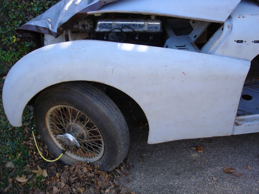
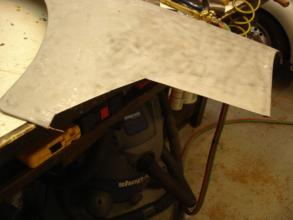
The original (red) wing is both hit, bondo'd, drilled, and rusted through. I brought it out of storage, but also went straight to the donor car, hoping all the while that the donor wing was in better shape. This is it. On first glance it looks pretty decent...until...

DSC03469.jpg

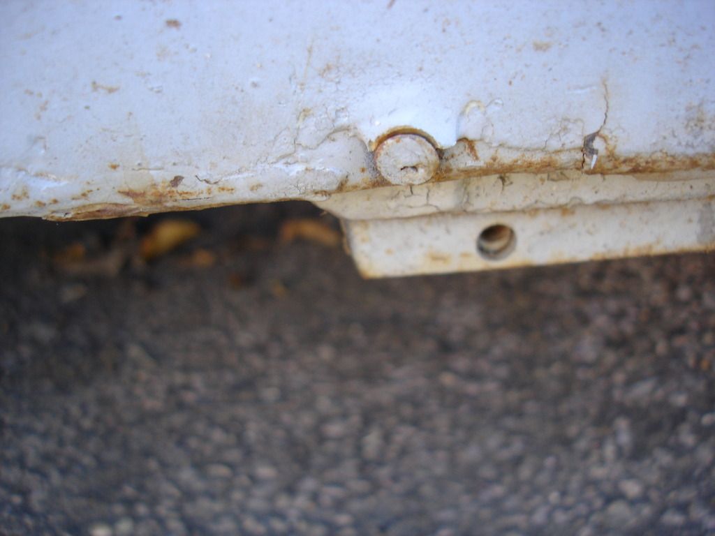
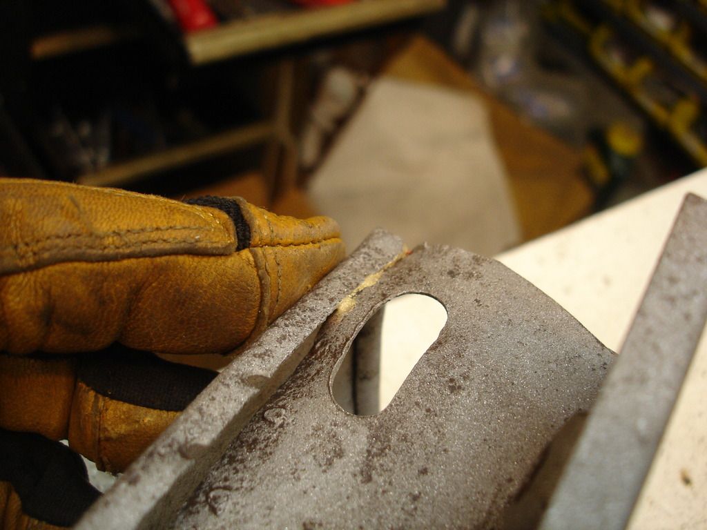
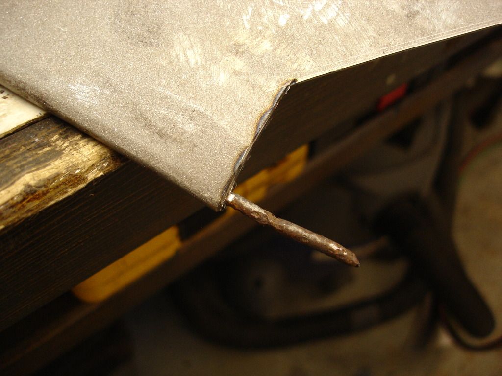
Yes, this is a nail holding the donor wing on! I thought I'd seen it all, but this shows, when it comes to old cars you can not even imagine how bad people can treat these cars.

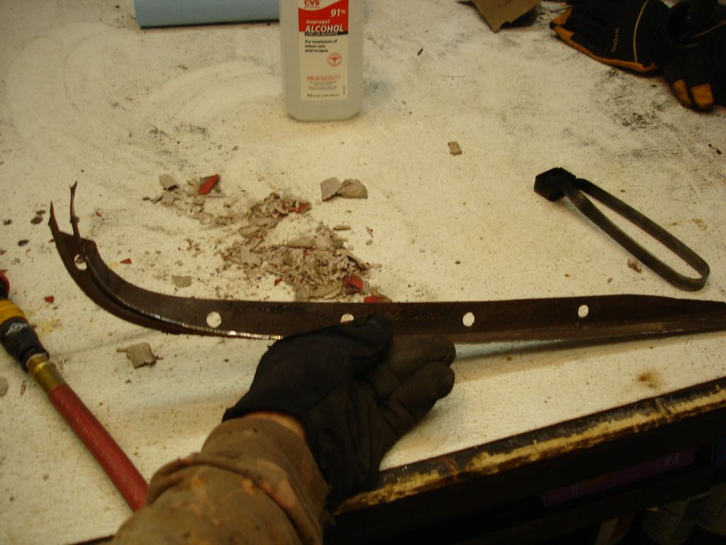
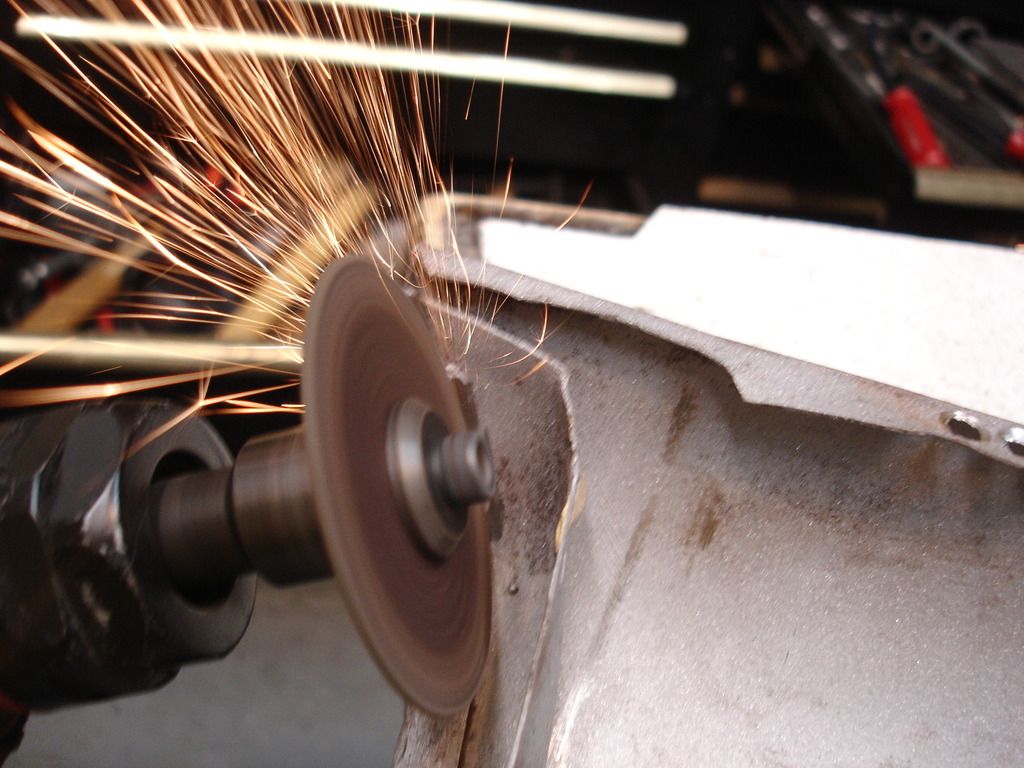
The following are just some pics showing what I was confronted with on my 2 left wings...

DSC03470.jpg

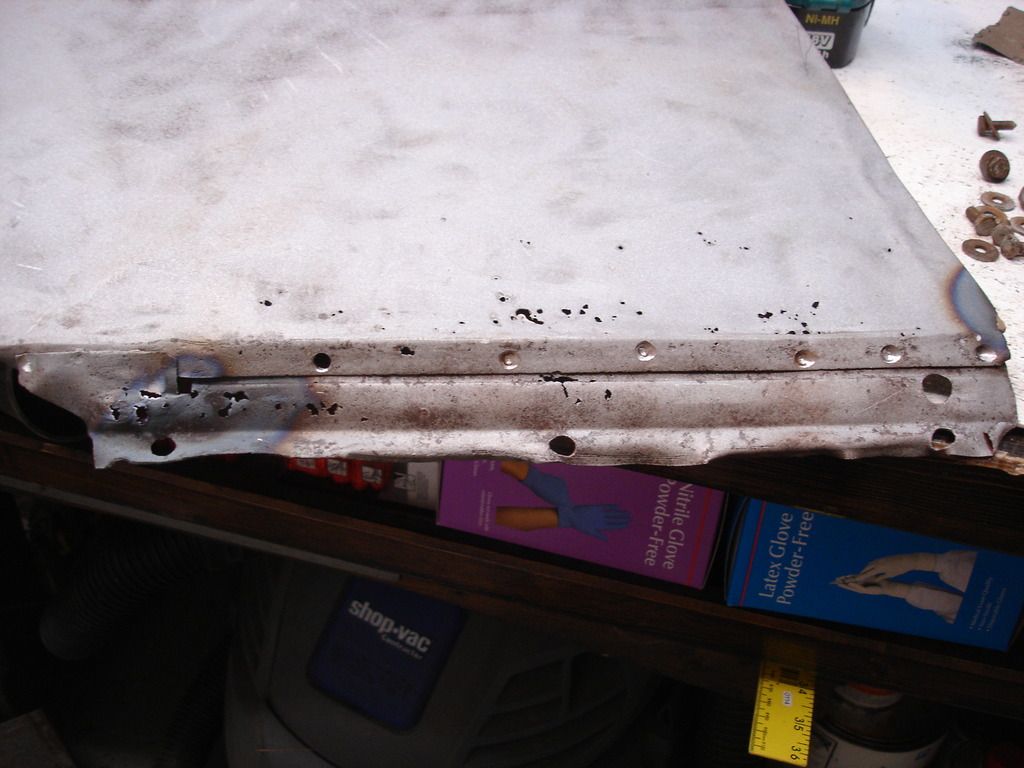
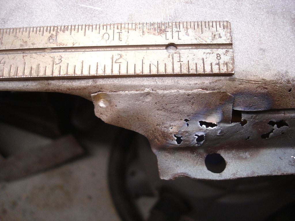
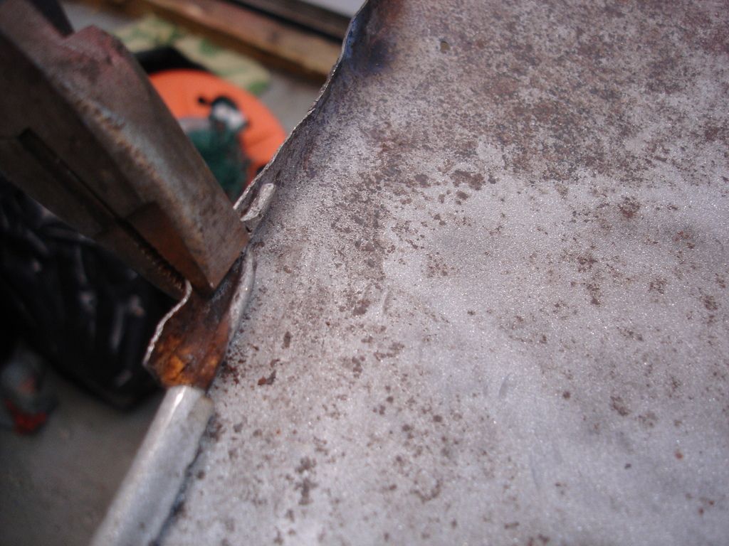
This shows the original wing flange that bolts to the front apron. An obvious front end ding that was never straightened.

DSC03472.jpg

Original wing front flange from a different angle. Not shown is that the flange where it meets the scuttled is also rusted out.

DSC03473.jpg


DSC03474.jpg

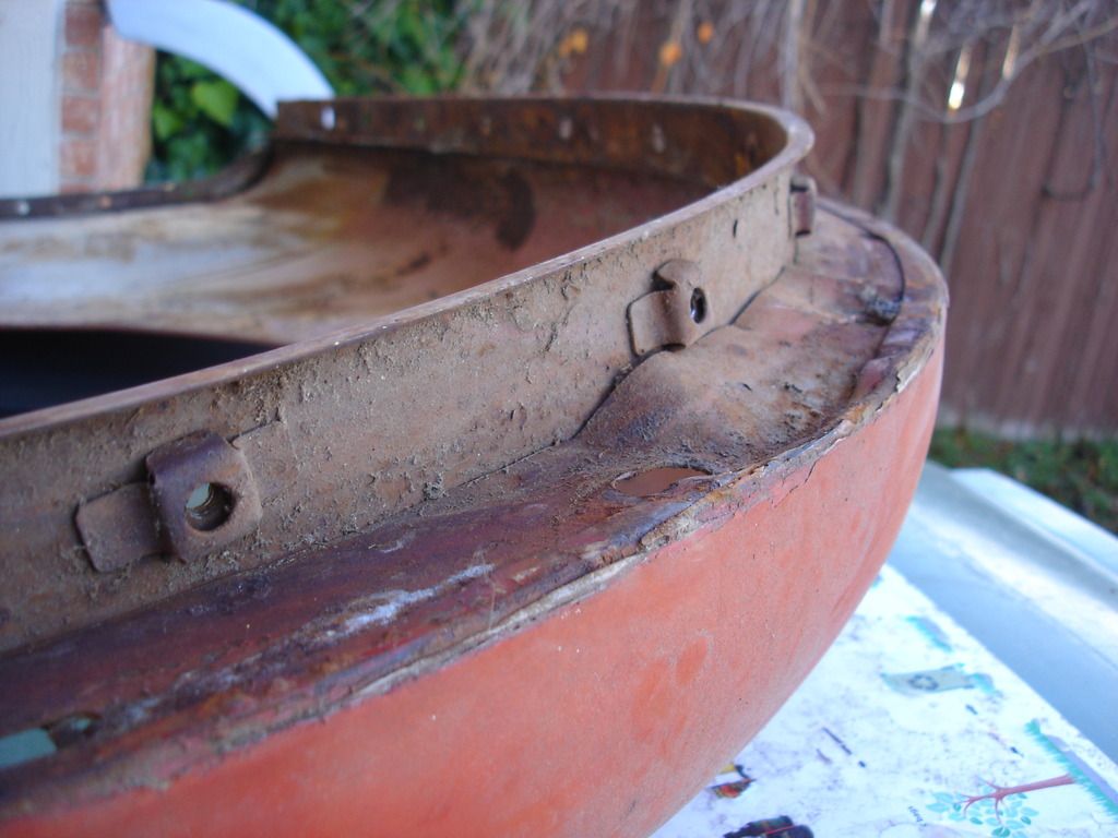
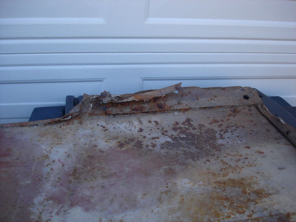
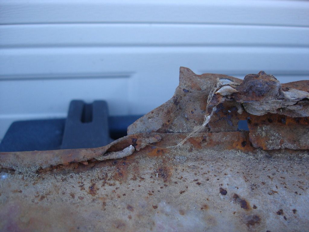
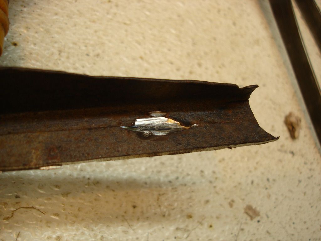
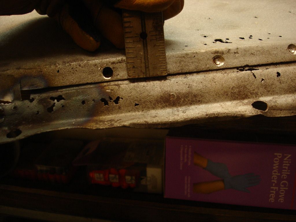
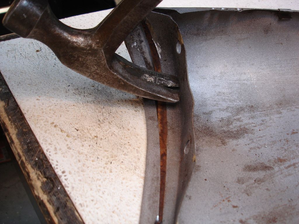
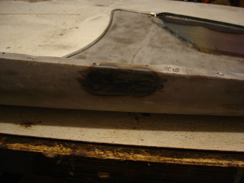
These are of the lower mounting flange on the original wing. That mangled strip of rust is part of the inner sill that came off with the wing. It came off with the wing because it was brazed onto it. If you guys have followed this ordeal from the beginning, you remember how much I like brazing during body work...NOT!

DSC03475.jpg

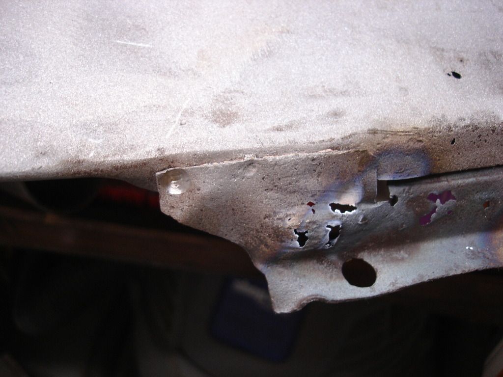
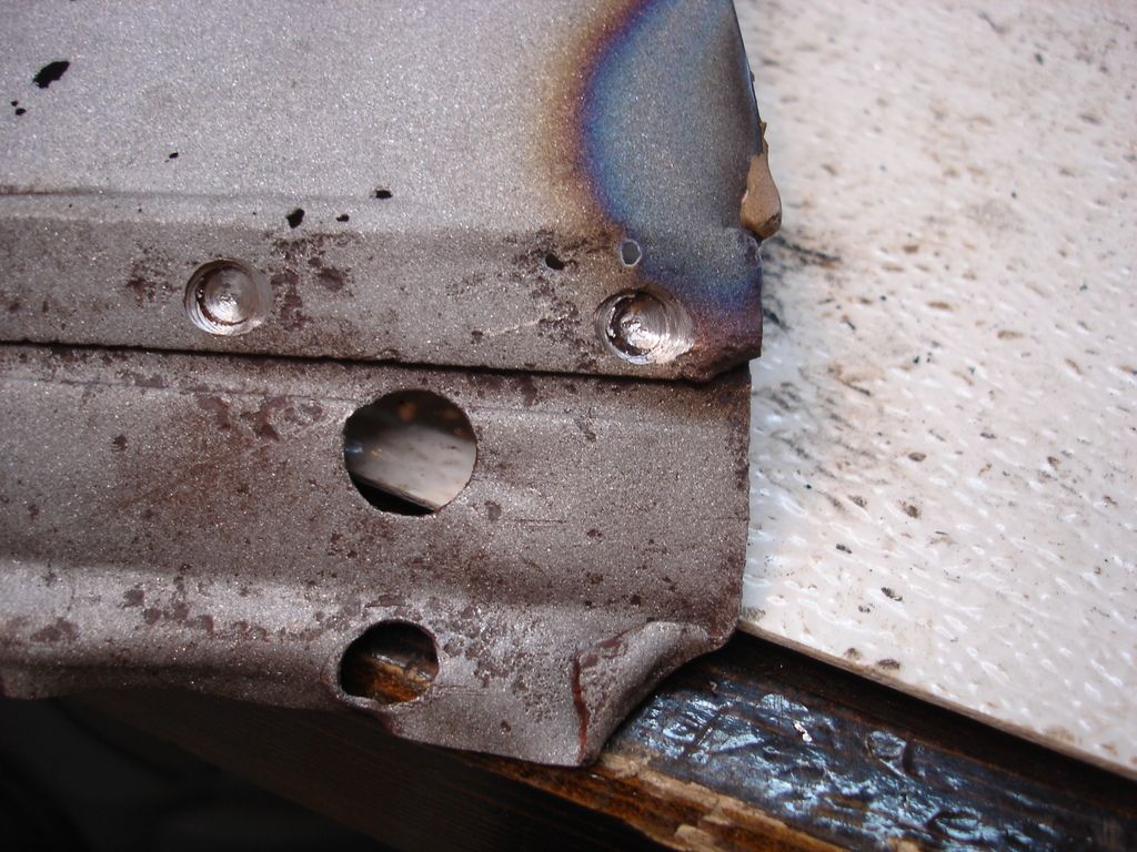
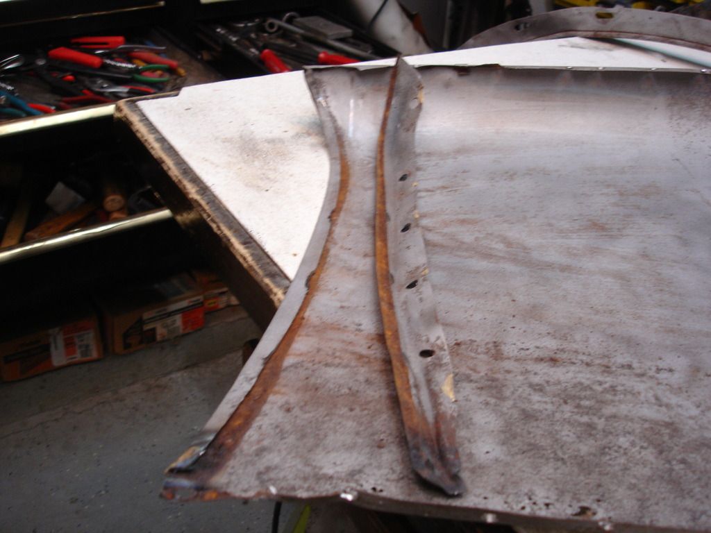
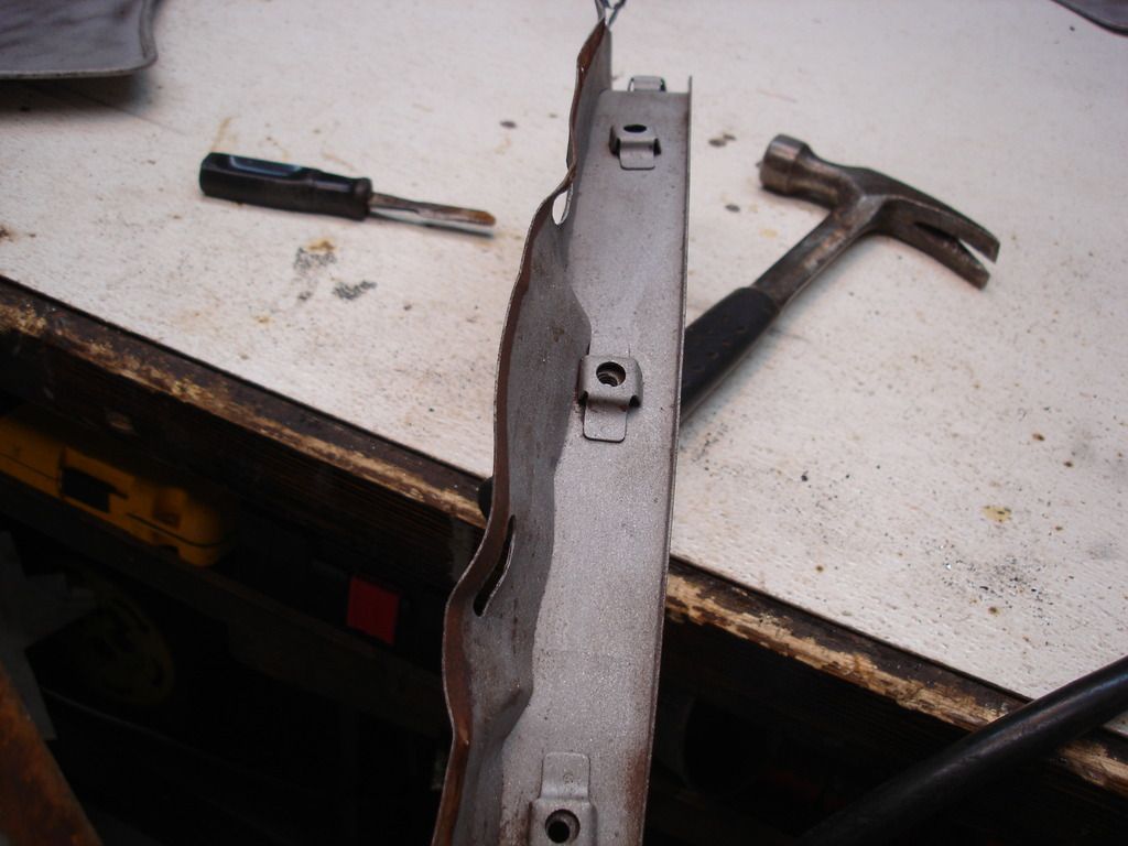
And, here is the rear mounting flange on the original wing. No, it is not supposed to be flat like that. This wing is mangled from top to bottom and front to back. And, I haven't even taken the bondo off yet!

DSC03476.jpg

Bottom flange again, This is supposed to stick out from the wing at almost 90 degrees. It is flat to the wing because it is so rusted that it has no strength and flattened when I simply laid the wing on the ground.

DSC03477.jpg

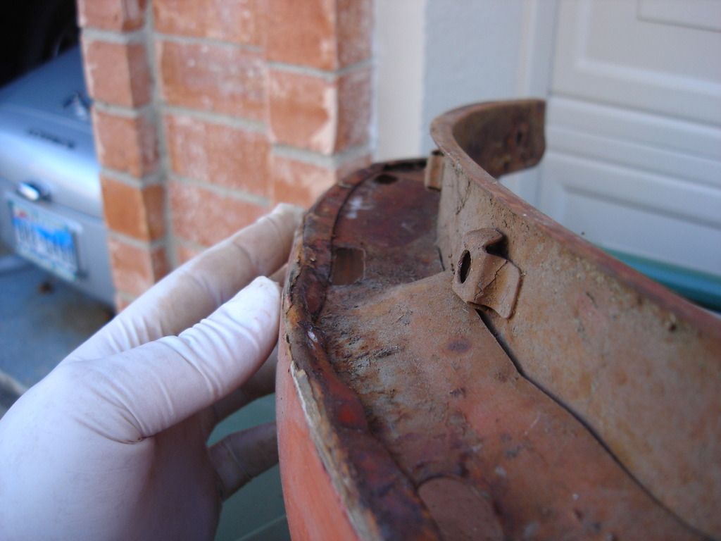
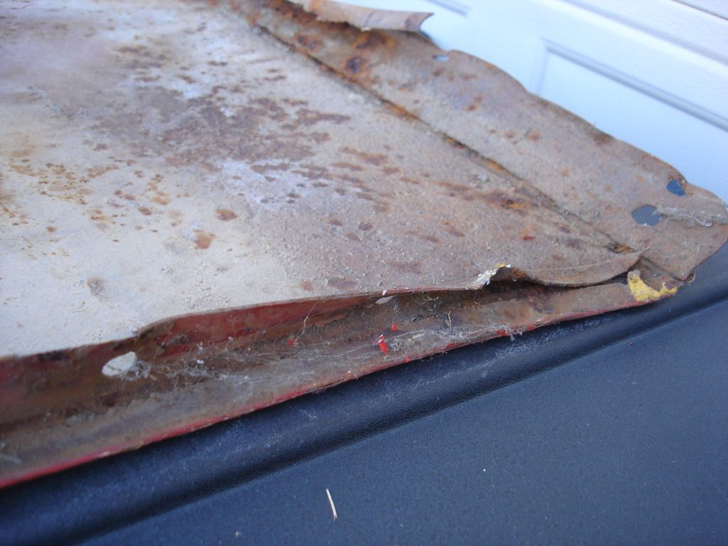
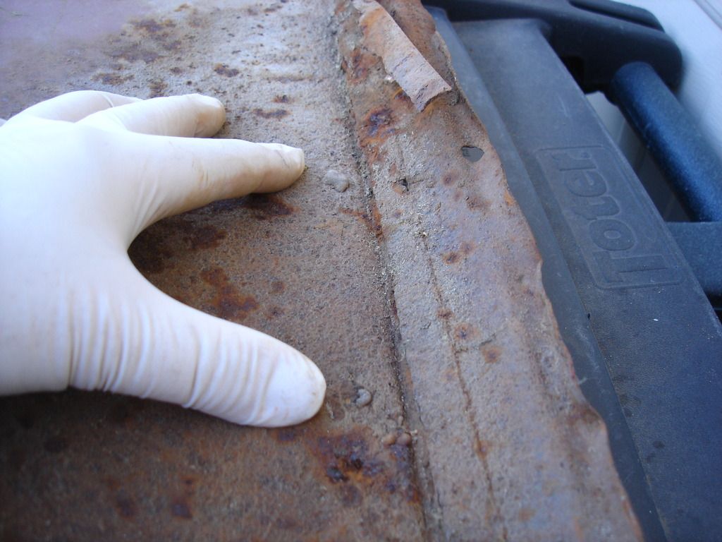
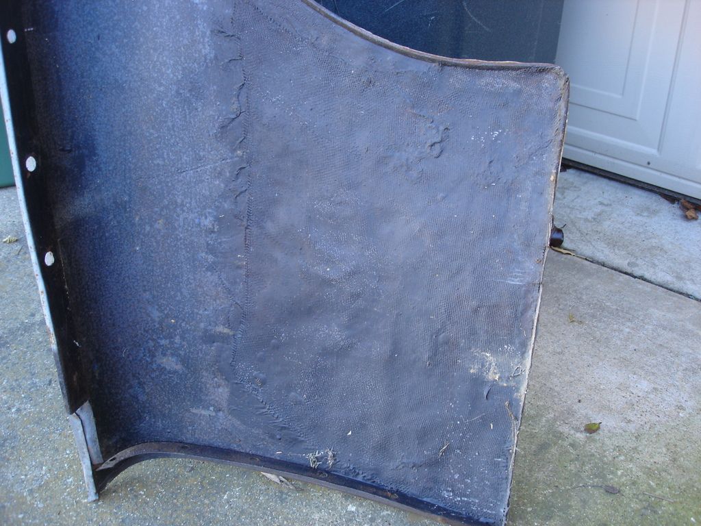
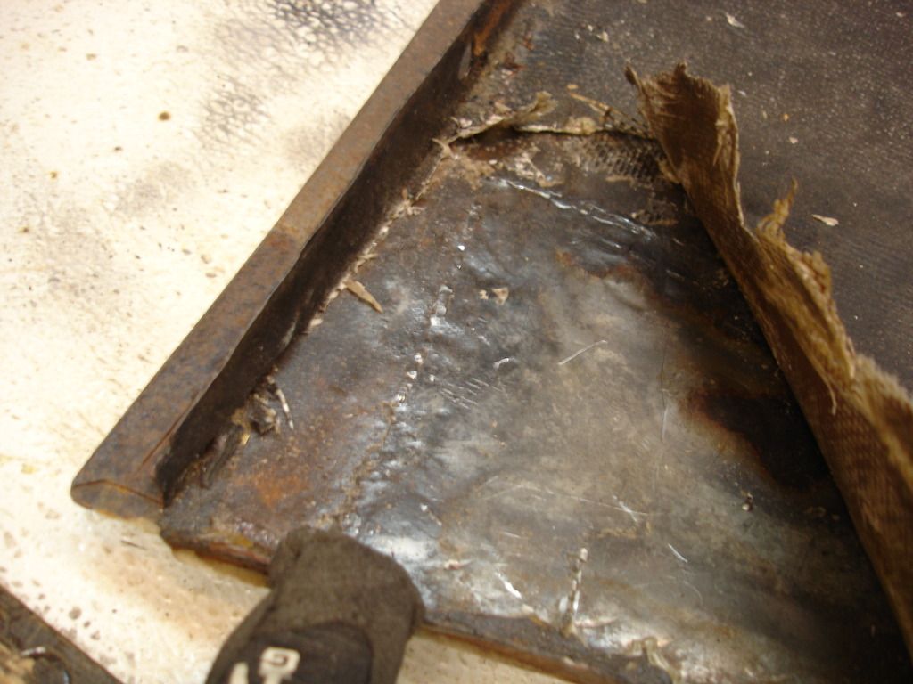
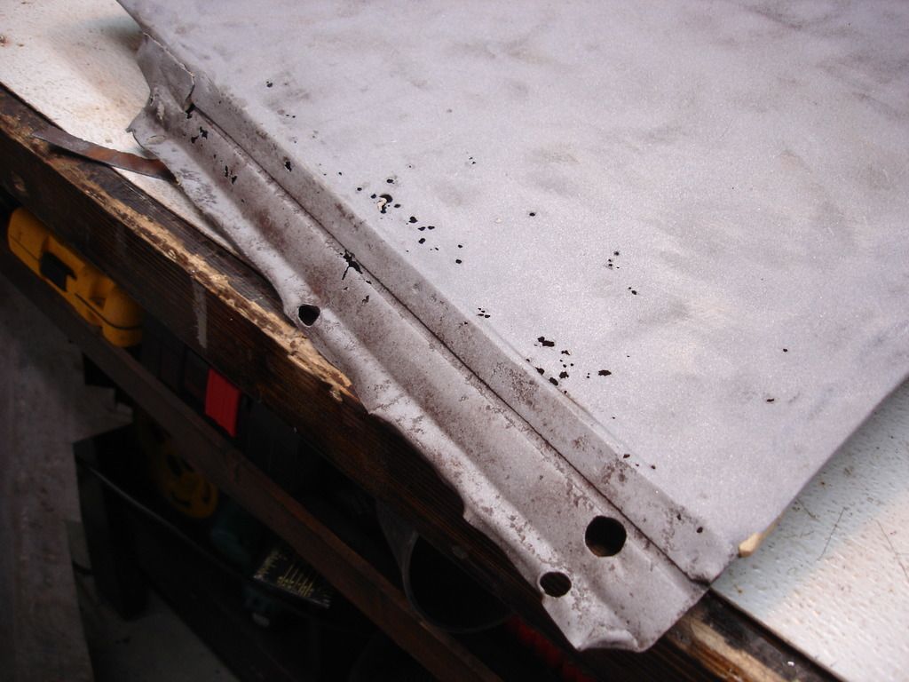
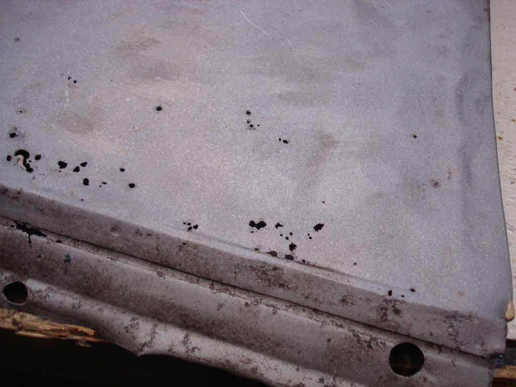
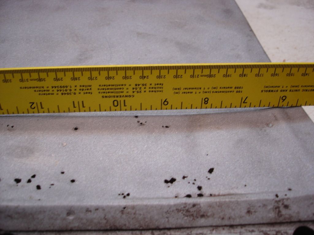
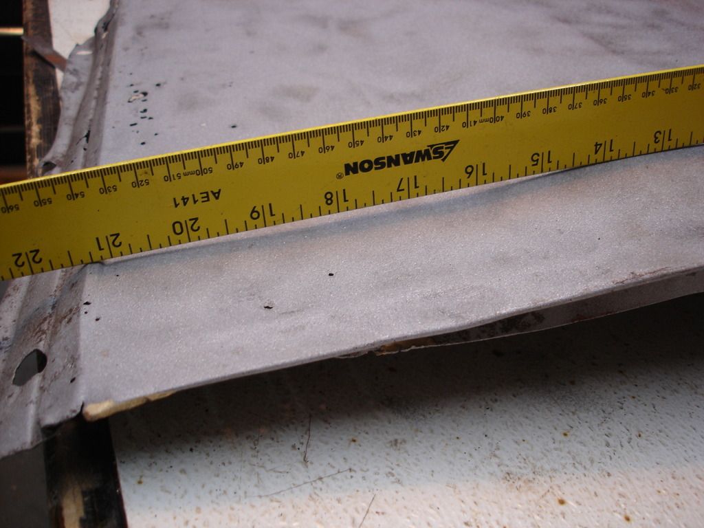
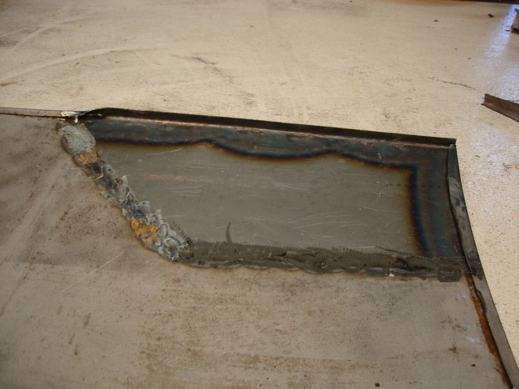
Moving on to the "spare" wing from the donor car, this is what it looks like on the inside once it came off. Right away you will notice there is no lower mounting flange...at all. The fabric weave pattern is fiberglass cloth...never a good sign. As I ran my hand across the cloth, I realized that the entire lower wing is "walnutted", to quote a term Steve used. Walnutted is when someone banged on the metal with (what can only be guessed as) a ball peen hammer. It results in hundreds of little dome shaped bumps.

DSC03479.jpg

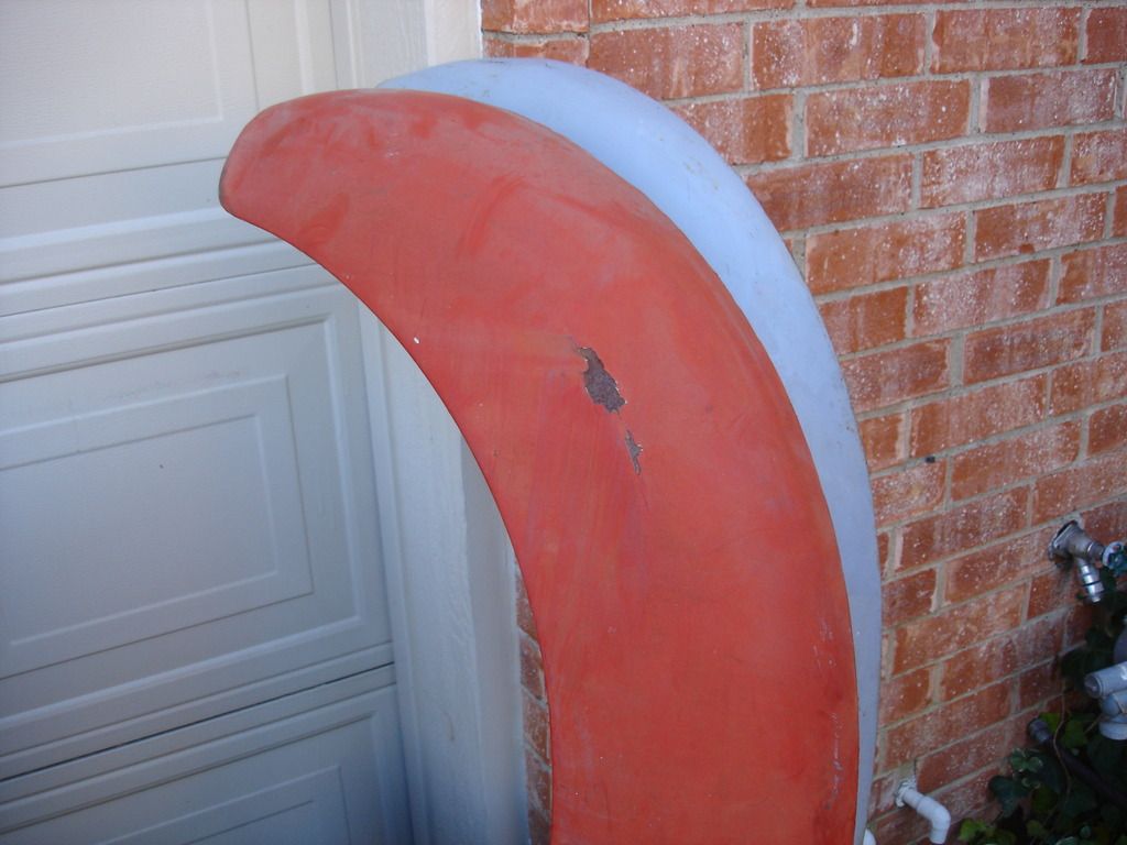
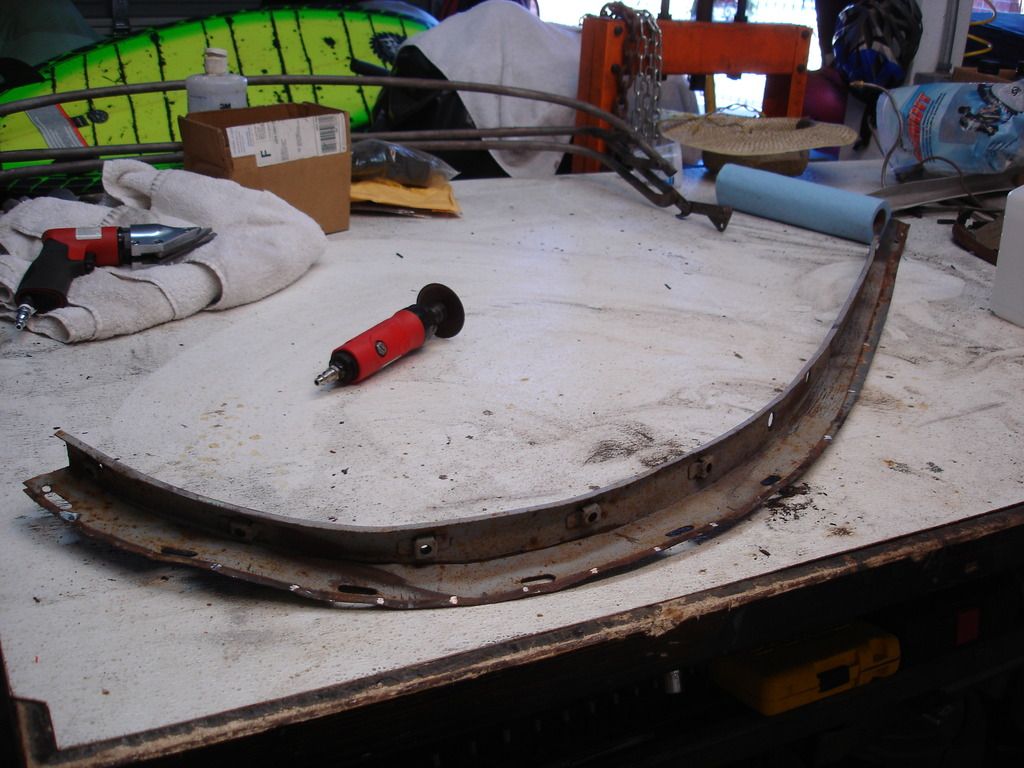
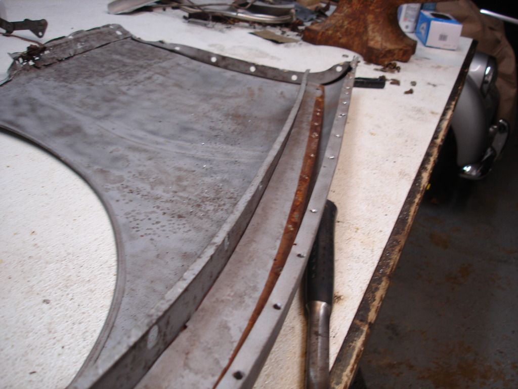
The 2 wings standing together. The red is the original. You can see a scrape and dent above the wheel opening. This is just one of many dents I later found under the bondo.

DSC03481.jpg


DSC03482.jpg

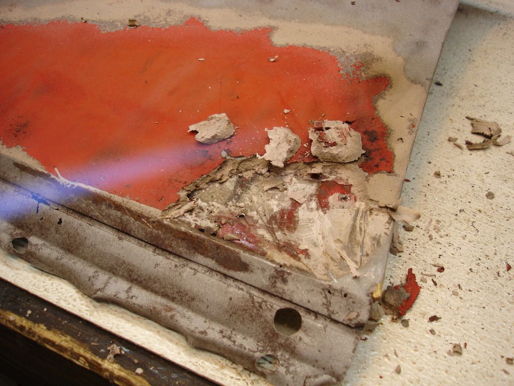
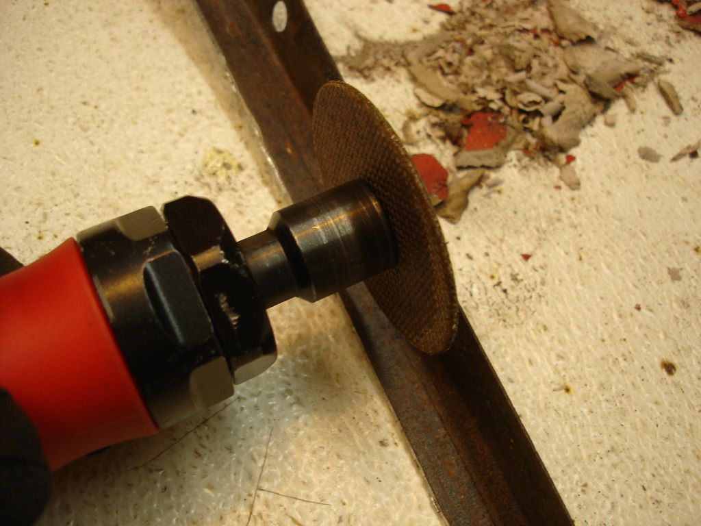
I would really dislike glass and bondo, but unlike brass, it comes off with a little heat from a torch and a scraper. So, although annoying, not at all difficult to remove to get back to basics.

DSC03483.jpg

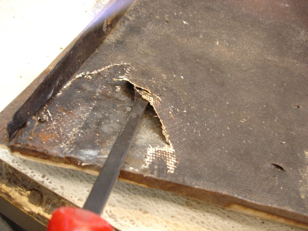
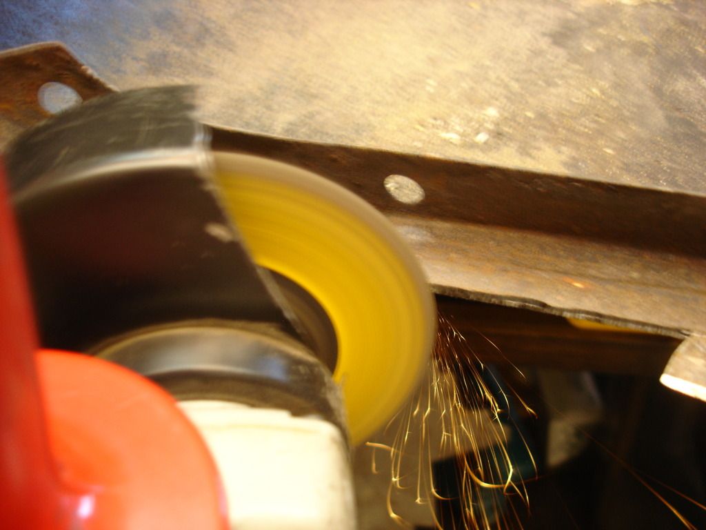
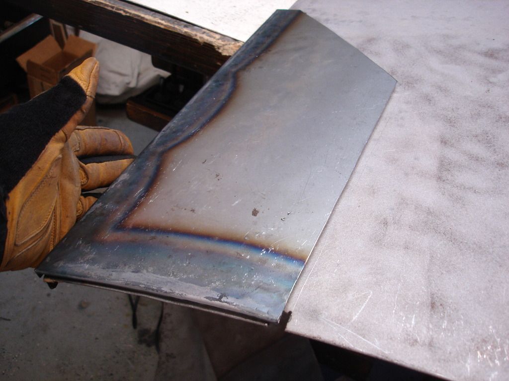
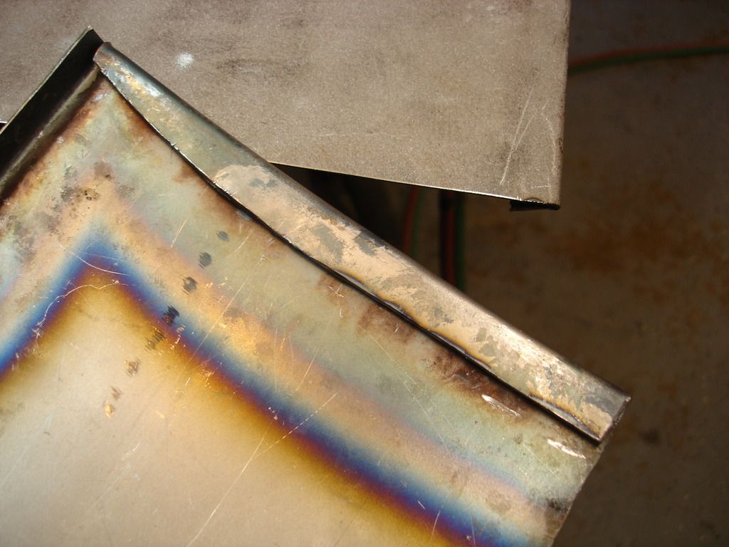
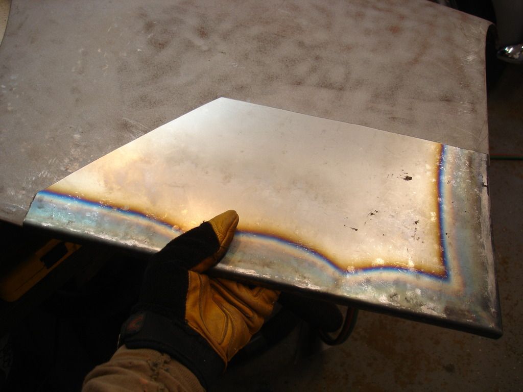
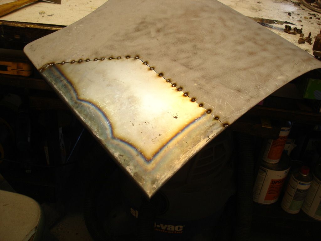
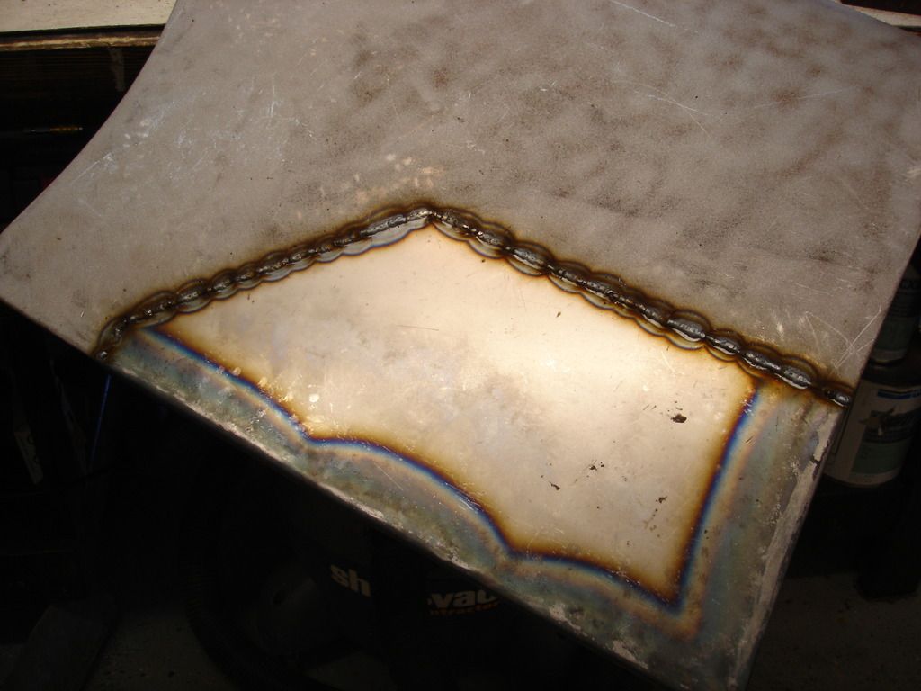
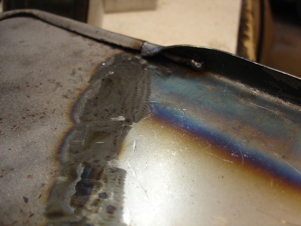
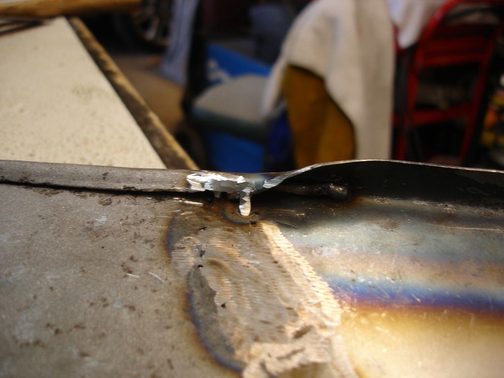
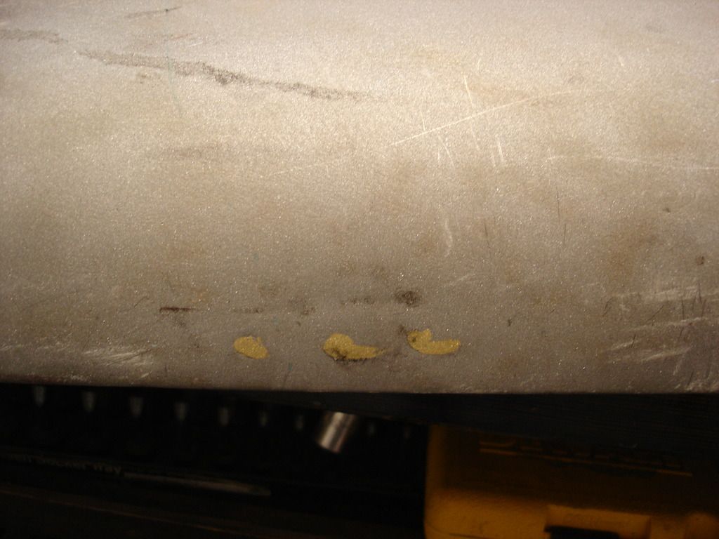
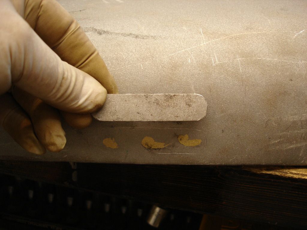
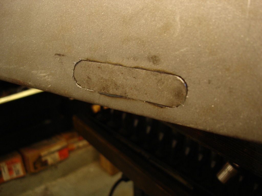
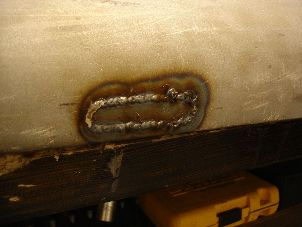
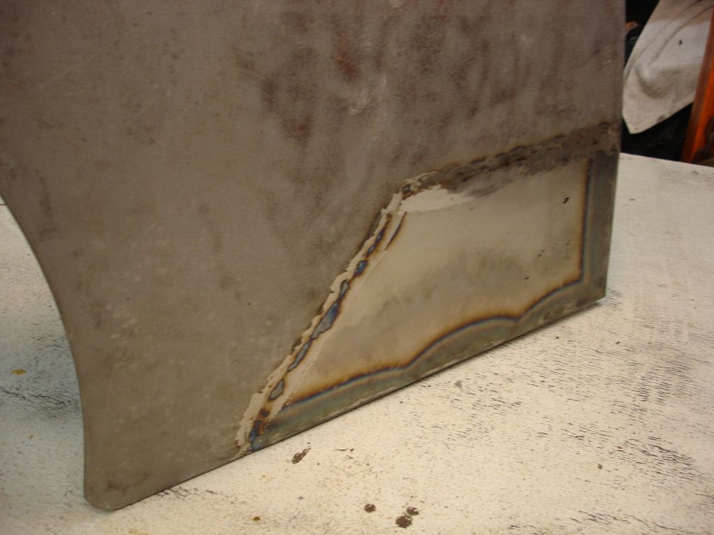
The first thing I noticed as the glass cloth came off the spare wing is that there is a patch welded into it. It's not a terrible patch job, but it was never finished. After welding in the patch, it requires the bead to be ground down and some hammer and dolly work to smooth the panel. I think the PO got in over his head, and didn't even try to smooth the panel.

A quick tip...

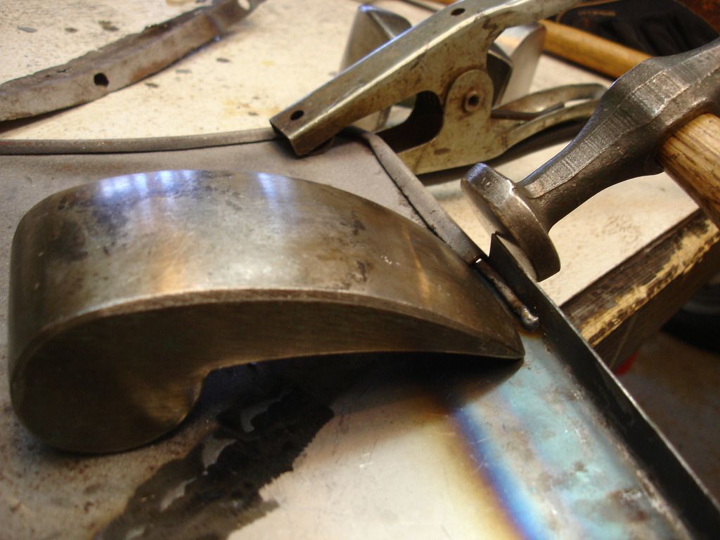
As a rule, never hammer on a panel without a dolly behind it. If you hammer on a plain panel, the metal does not bend as you think it would, but rather is flexes and springs back. So, with normal "tapping" you accomplish nothing. When you realize that the flexing is just "spring", and not doing anything permanent, your instinct is to hammer harder. If you do, you have to hit the metal so hard that it now leaves hammer marks. The result is...."walnutting". The dolly has mass that reacts against the panel as you tap. This prevents the metal from flexing, and allows it to bend. So, in general, never hammer without a dolly. That is the single most damaging mistake you can make as a novice bodyman.

Walnutting is very time consuming to remove. The reason is two-fold.

First, when you bang on the panel, the metal stretches. That stretching has to be removed by shrinking the panel. On a small panel that shrinking is not hard, but on a large flat panel, like the lower section of a wing...it is both tedious and mind numbing. Each little low and high spot has to be worked repeatedly to get the panel back to flat.

Second, when you walnut the metal, you have work hardened it. Work hardenening happens when you stretch the metal well past it's yeild limit. The only way to work it further after it is hardened is to heat it red hot and allow it to cool slowly. This "resets" the grain structure in the metal, so it becomes soft once again. Again, this is not hard to do on a small or rounded panel...but it becomes graduate body work when the panel is large and flat. The heating causes distortions that have to be worked back out. If you walnutted the panel to begin with, there is no way you will know enough to remove the heat distortion after heat treating the panel. Catch 22.

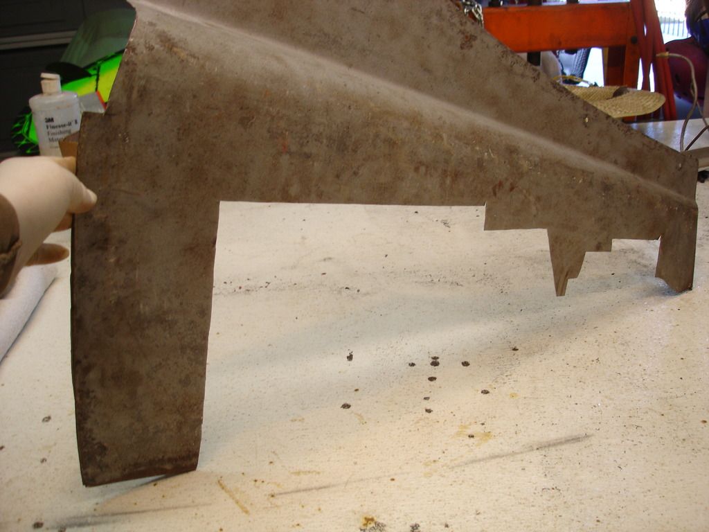
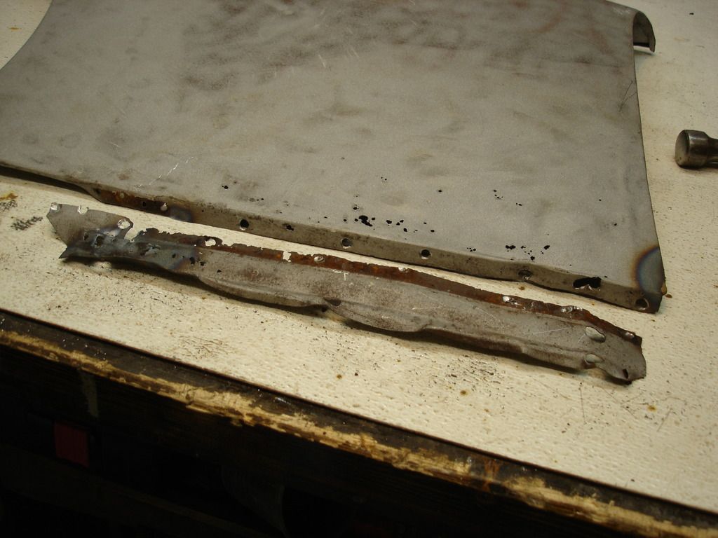
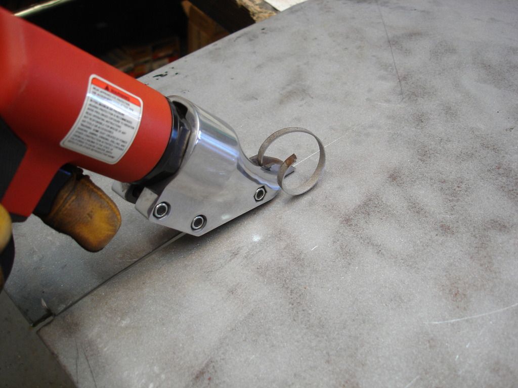
So, the spare wing is a write-off in my book. But, it will serve a purpose!

DSC03480.jpg

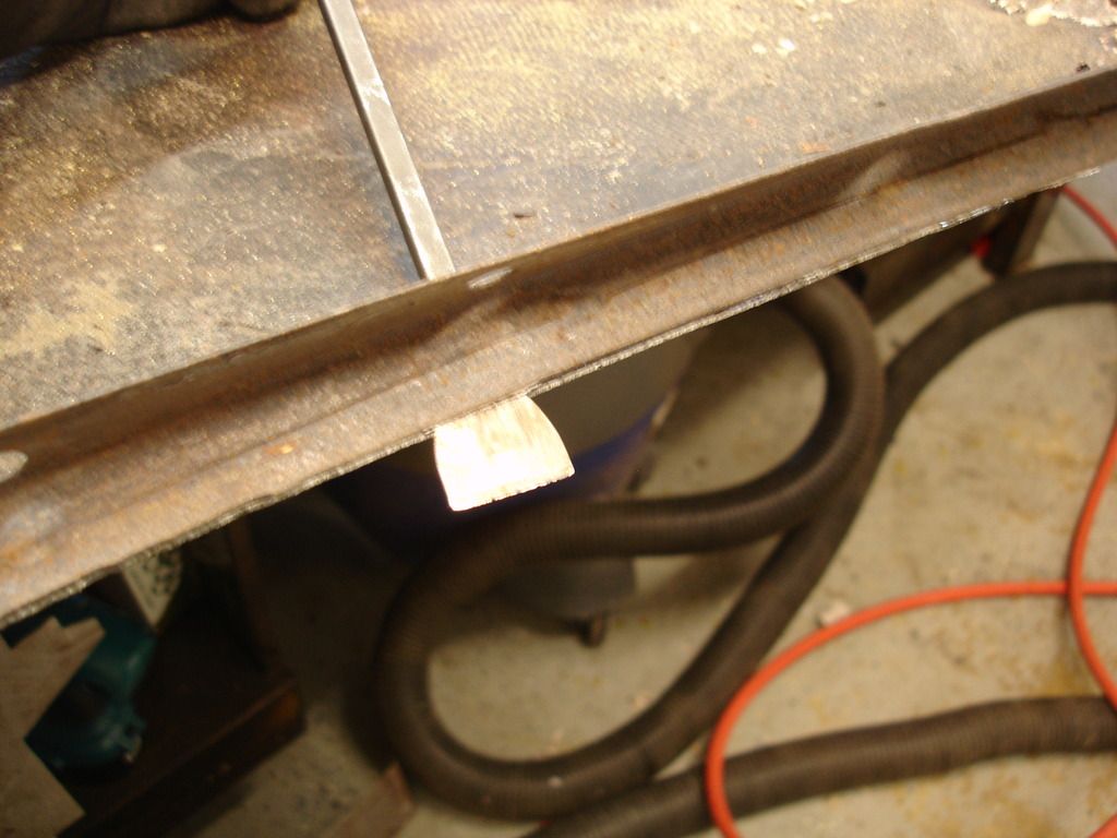
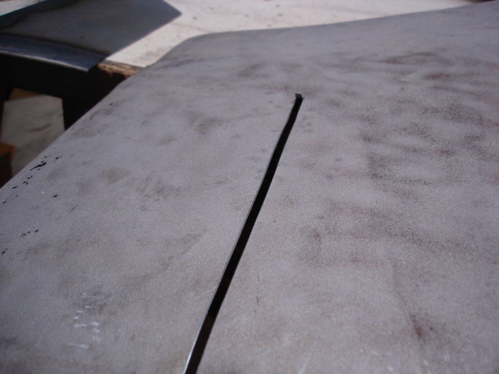
This is my trusty old door panel I have been using for patch material...it's almost consumed. I will cut out the upper portion of the spare wing and blast it to use as more patch material. Any flat(ish) metal panels I can find along the way will get used at some point.

Something I found interesting. My teenage son wanted to see the new Star Wars movie, so we went this week. As I was sitting there, waiting for the movie to start, I remembered myself as a teenager watching the original Star Wars (now renamed "New hope") in 1977...it dawned on me that the TR2 I am working on lived it's life, died, and has been parked in the back field for that entire 38 year period. It has not run since the original Star Wars was at the box office!
 
Since the spare wing is a write-off, let's get to work on the original wing. As you saw, the flanges are all beyond repair. Fortunately, the flanges on the spare wing ...at least the 2 that are still present...are not terribly bad. I will remove the upper and rear flanges from the spare to use on the original wing. This has the added benefit of making better access to the back side of the wing to work out the dents. Here we go...

DSC03484.jpg

The rear flange is crimped under a fold in the rear of the wing skin and spot welded. This is identical to the way the door skins were attached. This time around I do not need to save the skin on the spare door, so I can grind off the crimped edge so it releases the flange.

DSC03485.jpg

Here, I am breaking the crimped edge loose with a thin scraper after it was ground off.

DSC03486.jpg


The flange breaks loose, but still has a thin strip of the wing skin that was ground off. This is spot welded onto the flange in a handful of locations.

DSC03487.jpg


DSC03488.jpg


The spot welds can be quickly ground off with a disc grinder, so the flange is off and ready to re-mount on the original wing.

DSC03489.jpg

The upper flange is spot-welded onto the wing skin. In traditional fashion, the weld spots get drilled and popped apart.

DSC03490.jpg

The lower flange is also spot welded. I do not have a usable lower flange, so this part will be fabricated later. I. Need to save this one as a pattern. I'll use my finished TR3 to double check my measurements, since this one is so badly mangled.

DSC03491.jpg

Once blasted, this is the lower rear of the original panel. It will take a patch in this area. Although patches are available from the big 3 suppliers, I avoid new body parts when I can. my experience is that the new pats are more work to fit than the work it takes to repair an old part. We will fab a home-made patch for this area.

DSC03492.jpg


DSC03493.jpg

This just shows that, in addition to the rust, the lower wing is also dented in. I will work all the dents out of the wing BEFORE I make any attempt to fab a patch. You must get the panel to shape before you attempt to complicate the situation by adding new metal.

DSC03494.jpg

Here is the ratty flange being removed from the original wing. It will be replaced by the better, but far from perfect, spare flange. This is being done by drilling through the outer layer of metal, and then using a 1/4" punch and hammer to drive the panels apart at each weld spot. In other words, the punch is placed through the drilled hole in the outer (skin) panel so it rests against the lower (flange) panel that was not entirely drilled out. Then rap the punch with a hammer and the weld breaks free. No chisel work! But, this technique only works on some panels when removing welds. Orientation of the parts is the key.

DSC03495.jpg

Of course I could not finish scot free. The corner was brazed. This, again, has to be removed by heating the smell red hot and rapping the panel so the brass flings off in scalding hot balls around the shop!

DSC03496.jpg


DSC03497.jpg


Here, I have removed that little mangled strip of inner sill that was brazed to the lower flange.

DSC03498.jpg


DSC03499.jpg


DSC03500.jpg

Since this flange has to be duplicated, I took plenty of pics and measurements to make sure I get it right when it comes time to fab it.
 
DSC03501.jpg


The lower flange removed. It will be set aside as a pattern for the new flange.

DSC03502.jpg


I now turned to removing the rear mounting flange from the original wing. Since I have to save the skin intact, I cannot grind the edge like I did on the spare. Here I am grinding the weld spots down.

DSC03503.jpg


DSC03504.jpg


In this pic I am merely tapping the flange out of the crimped skin. Once the welds are ground, it comes out easily. Once out, I will spread the skin slightly with a chisel so the good flange can be re-installed without binding.

DSC03505.jpg


The upper flange is removed from the original wing. Now the accident damage is very visible. Between the rust and denting, this will get tossed. I may try to recover some of the nuts and cages for later.

DSC03509.jpg


Now that all the peripherals are off the wing, I spent most of a day with a hammer and dolly removing all the dents. I spared everyone the details, but summarizing, it was really easy since I had full access to the back side with the flanges removed.

Here I have turned to the little wire that is crimped around the wheel opening. I have cut the sheet off the wire and unfolded the crimp in this area in preparation to install the patch.

DSC03510.jpg


This is the patch, cut, formed and ready to install.

I need to discuss the metal used to form our TR2/3's at this point. Early in the project I measured and determined the metal used on the body was 18 gage. Since then, I read a handful of articles that state that 20 gage was used for the body. So far I dodged the issue by retasking old metal. Unfortunately, this is the holiday season and my metal supply is closed. I fashioned this patch from 16gage steel sheet from Lowes. They stocked 16 and 22 gage, with nothing in between. I rationalized using the 16 gage for the patch. This area of the front wing is always the first place on the car to rust out. 16 gage is twice as thick as 20 gage...so it will take twice as long for my patch to rust through. See, I can rationalize anything!

Back to work....

DSC03511.jpg

My last trip to Northern I picked up this cheapo pneumatic shear. Only $41...thanks to our friends in China willing to work for 14 cents and hour. If you remember my earlier demonstration of how tin snips put a curle into your metal, pneumatic shears do not distort the metal at all. I have always made due with hand shears, but this car has left me worn and broken. I caved and forked out the dough for the power shears. I do recommend them if you plan to do a significant amount of metal work.

DSC03512.jpg


And this pic shows why I recommend the investment. Look at how beautiful the slice looks. No follow-up with a hammer and dolly.

DSC03513.jpg


DSC03514.jpg


Here all the bad metal is cut out to the shape of the patch. Note that I did not cut the reinforcing wire that supports the wheel opening. This will be re-wrapped into the new metal once the patch is installed.

DSC03515.jpg


This shows the back side of the patch panel, showing the wrapped edge that will crimp the rear flange, and the raised lower edge. All this was done by hand using a vice and anvil.

DSC03516.jpg


DSC03517.jpg


DSC03518.jpg


In normal fashion, the patch is tacked into place and finish welded. After each tack, remember to use a hammer and dolly to ensure the panels match absolutely perfectly. The hammer and dolly are needed occasionally to true up the panels as you make the finish weld.

Tip...

Although you can weld the patch in in one long weld from one edge to the other, it is best to do it in short welds of 1 inch or so. This prevents the heat from building up, which in turn leads to distortion. I started at the left edged and ran a weld between the first 2 tacks. I then moved to the right edge and welded between those 2 tacks. I continued to alternated back and forth. Occasionally, when the metal felt like it was getting hot, I paused several minutes to let it cool.

Doing the weld in this fashion minimizes the distortion, so the final hammer work is greatly reduced. Also, remember that when I say I ran a weld, it is really several half-second bursts, pausing a second or 2 between bursts.

DSC03519.jpg


DSC03521.jpg


DSC03522.jpg


DSC03523.jpg


This is finish work of wrapping the reinforcement wire back into the metal. You can also see I have ground down the weld beads on the patch panel.

DSC03524.jpg


Now I turned to cleaning up the odd problems with the wing. Here is a patch piece for a 1/2" hole. I have no idea WHY there is a 1/2" hole in the wing?? It is too small for an antennae, and too large for a mirror. I honestly think some individual put this in just for the purpose of frustrating me 50 years later!?! There can be no other reason for it.

DSC03525.jpg


And, speaking of frustration...I have mentioned I dislike brazing, haven't I? Here there are 3 small holes that were brazed closed. At least I can see a reason for these...some long lost wing mounted mirror, that got ripped off at least once. I see no way that wing mirrors will ever stay attached, but that's just my observance.

DSC03526.jpg


DSC03527.jpg


DSC03528.jpg


DSC03529.jpg


DSC03530.jpg


Here is the fix for the brazed spots. I actually considered leaving them in, as brass plugs. But, then, I thought about the level of frustration I would have when they popped back out after my final paint job. That thought only lasted a second or two before I decided to fix it right!! 10 minutes with the snips and a welder now likely saved me hours of future cussing and wing re-painting later.

DSC03531.jpg


DSC03532.jpg


Wrapping up the week, here is the finished patch, ready for re-sand blasting and finish dollywork. Double the thickness to boot!

From this point I will leave the wing skin out on the bench this week. Every time I pass by I will feel for inconsistencies, and tap them out. No matter how long I check, I will always find more! The closer the panel gets to perfect, the more you tend to notice the very fine imperfections. It's very important to not try to finish bodywork all at one sitting. You have to step back and take a break occasionally. Every time you take a fresh look, you'll find something to tap out. Likewise, at some point you have to stop looking or the panel will never be finished. For me, that sweet spot is about a week.

After a week of random checks and taps, I'll get around to installing the flanges.

Cheers 'till then!
 
Last edited:
Back
Top