• Hi Guest!
    If you appreciate British Car Forum and our 25 years of supporting British car enthusiasts with technical and anicdotal information, collected from our thousands of great members, please support us with a low-cost subscription. You can become a supporting member for less than the dues of most car clubs.

    There are some perks with a member upgrade!
    **Upgrade Now**
    (PS: Subscribers don't see this gawd-aweful banner
Tips
Tips

backfire...ect.

Hi Greg

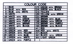
OH OK, but only one White wire comes from the Ignition switch to the coil that second White wire that is flapping in the breeze may be the B/W wire to the cut off switch but you can not tell for sure as no Black is showing and I blew the picture up pretty big. Still a bit of a mess in there though. :D---Keoke
 
Hey Greg -

Another good test is to put your tongue on the bare wire and give the starter a spin.

/bcforum/images/%%GRAEMLIN_URL%%/devilgrin.gif
 
Alan,
I could also put you on my “Ignore User” list (you’d be the only one). /bcforum/images/%%GRAEMLIN_URL%%/rolleyes.gif A handy feature the forum software provides.
 
Hi Keoke,
Yeah, I blew up the photo in photoshop and didn’t see a black tracer either. <span style="color: #3366FF">Rick, could you confirm if there is one?</span> Here is a section of the wiring diagram from the shop manual for the 100-6. #9 are the white wires. I have highlighted them to make it a little easier to trace. At least in the diagram, it shows 2 wires.
5219-100-6wiringdiagram.jpg
 
GregW said:
Hi Keoke,
Yeah, I blew up the photo in photoshop and didn’t see a black tracer either.
Hi guys,
"Slightly off topic but related -

Greg's wiring diagram was likely scanned at fairly high resolution & then cropped. It comes out fairly clear.

OTOH -
If you "blow up" an image, such as the actual wiring pic, shown above, in Photoshop, or any of the other similar programs, & the original was low resolution such as 72 dpi, blowing it up does not increase the resolution, (add dots) so you end up with a very grainy low resolution but larger pic. Still not any easier to see small detail. I have not found any way to add resolution/detail to the blow up if it was originally low resolution. What is your experience?
D
 
Well Geg, I see what the good book says. But this being a schematic as apposed to a detailed wiring diagram I would think that second white wire actually goes from terminal A3 on the fuse block directly to the ignition SW. As shown it sure is the long way home. But this be British you know.- :G-----Keoke
 
OK Dave. Try this; Print the picture as a glossy print then take a Loup and examine the small areas in detail. Actually, Saving the picture to "My Picture File" and then using the zoom tools to examine it helps in the viewing of details too.---Keoke
 
Greg.........sorry about the misspeak on the black wire. The fried one came from the dizzy to the white wire coming out of the harness. I got it mixed up with the one coming from the coil to the frame bolt holding the harness. (hard to see) There was a lot of extra wire there and you are all correct about the wiring on this car. It was restored about 15-20 years ago and a fine job was done on everything but the wiring. My mechanic has had to patch a number of things lights, flasher, etc.

My fear is, if I put the points back in, won't I have to rewire them. I'm not sure I have the skills to do this. Question? If the current was coming from the battery though the white wire.......to the black (fried wire) and then to the elec ignition, what would cause it to melt the wire?
 
Hi Rick

The Pert wiring was improperly installed in the Dizzy. Consequently, it appears that a short occurred in that wire at the top plate as the wires are routed to the rubber insulator. This speculation is enhanced if we notice that the black wire extending above the top plate is undamaged.---Keoke

When a small wire hard shorts to ground and is carrying a size able voltage a tremendous increase in current is generated. This high current is transformed into heat in the circuit causing the insulation and the wire to fail.
 
Dave Russell said:
I have not found any way to add resolution/detail to the blow up if it was originally low resolution. What is your experience?
D

Dave,

IMO, the best program for this is called "Genuine Fractals"
Genuine Fractals

You can also use 'bicubic interpolation' in photoshop to increase the resolution. It's best done in multisteps instead of one big jump in resolution, image size. Here's a good article on the subject with links to other software options.

resolution

Cheers,
John
 
Hi Keoke,
I recently replaced the wiring harness with a new one from Brit Wiring. The wiring was actually as Greg shows. "The long way home"

The feed path is battery hot at volt. reg. via wire #36, BN/BLU, to the "not switched" side of lighting switch, another #36 wire from the same terminal on the lighting switch to the ignition switch. Also other branches from the ignition switch "not switched" side.

From the ignition "switched side" to the coil via wire #9, WH. From the same coil terminal to fuse terminal A3, which is the switched but unfused side of the 17/35 fuse, via another white wire.

At fuse terminal A3 it branches to other switched but not fused circuits.

The fused terminal A4 then goes to other circuits which are switched AND fused.

I didn't design it, but it makes some sense that the shortest feed is to the highest current (lighting) first & then on to the lower current circuits.

I have attached a chart to match wire colors to the numbers on Greg's diagram.
D
 

Attachments

  • 5220-ColorCode.jpg
    5220-ColorCode.jpg
    106.1 KB · Views: 129
Well OK but like I said Dave, it be British and thats the long way home.---Keoke- /bcforum/images/%%GRAEMLIN_URL%%/grin.gif
 
Brit cars abound with things of "the long way home". On the other hand, they have many places where they took unwise short cuts. I wonder if it all balances out?

Maybe if AH's had continued into the 70's they would have added another fuse or two. After all, they DID add a fuse on the last cars.
D
 
If AHs continued into the 70's they would have ended up a complete pile of rubber bumpered, gulp valved, stromberg carburettored pieces of SH*TE.

Be glad that DMH had the foresight to see the writing on the wall and cut it off while the going was still good.

Alfa kept making their spyder (which in the 1960's was an absolute classic), but they couldn't help themselves and kept making them into the 1980's. The result? Any spyder other than a boat tail isn't worth a set of spark plugs on the Healey!
 
They did add a fuse on the last cars Dave ?--Where??---Keoke
 
Rick G said:
Greg.........sorry about the misspeak on the black wire.
No worries Rick, as I recall you were putting out a fire and then crying cuz you didn't have a beer anymore. /bcforum/images/%%GRAEMLIN_URL%%/cryin.gif

So about that loose white wire in the middle of the photo. Is that a white wire, or a white with black tracer?
 
Dave Russell said:
Keoke said:
They did add a fuse on the last cars Dave ?--Where??---Keoke
At the back in the line to the number plate lamps.
D


Somebody must have just drew it in, actually Dave, it never got there to my knowledge and remains an achillies heal or a smoking gun on the BJ8 cars to this day.--Keoke
 
I stumbled on this thread and saw the Keoke mentioned on the first page that I experienced a Pertronix failure when I got the unit damp. The unit I killed was a Crane/Alison ignition which I soaked when washing the engine of my Triumph. The Triumph now runs a Pertronix specifically because the module is protected under the dizzy cap. I have yet to kill a Pertronix module.

As was suggested on several previous posts to this thread, putting the points back in at least for a while is really prudent. The points will quickly help you identify if the problem is with the ignition module or is elsewhere in the system. The 10-15 second run time implies that something electrical is quickly overheating... assuming you have fuel.
 
Back
Top