• Hi Guest!
    You can help ensure that British Car Forum (BCF) continues to provide a great place to engage in the British car hobby! If you find BCF a beneficial community, please consider supporting our efforts with a subscription.

    There are some perks with a member upgrade!
    **Upgrade Now**
    (PS: Subscribers don't see this gawd-aweful banner
Tips
Tips

TR2/3/3A Beginning the TR2 Bodywork

Wow almost 13,000 views! Incredible story and wonderful journey John! Thanks!
 
Thanks, all for the support. I need it. I'll keep posting until I'm done, or I run out of photobucket space. Not sure until the end if it is a tail of inspiration or more a cautionary tail...!
 
Not sure until the end if it is a tail of inspiration or more a cautionary tail...!

It's both, obviously. Your info is doing a favor for those who might underestimate the skills and determination necessary for success.

Ed
 
It's a nice reminder of how bad a car can be it can always be saved! Plus it helps me out with mine, knowing that others are doing one just as bad, and to just keep on keeping on and the end will show up in sight!
 
John I did not remove the inner kick panel or firewall piece and wished I would have because the lower driver corner was rusted out. I opt to splice a piece with overlap on the outside and feathered that into firewall with glazing. The way you are doing it the car will have new metal in the spots where most cars are marginalized anyway, so your car will be a fine restoration. Just so you know the TRF battery box comes with taps on it and is thicker.

steve
 
Week 28

Nothing


Caught the flu and a DA hit my son's car in the parking lot, so the entire week was wasted on nowhere projects.
 
Week 29

Hard to get much done in the spring with a lot of family obligations. I think I have better luck during the holidays! Anyway, here's the update a bit late:


Starting on the drivers side, I measured exactly 2 inches up from the at the floor, and then fashioned a patch exactly 2 inches wide. You can see the firewall in the background, and how I had to do a good bit of shrinking to eliminate the stretch from the accident damage.


Cutting across to remove the rusted metal.


With the lower part cut out, access to the bottom leg of the inner wing was easier. Here, I started with a patch for the leg...but it didn't work! It turned out that, like many seemingly easy parts on these cars, it was angled in 3 planes. I am good with metal, but some angles elude me...and this is one of those. I scrapped this patch, and just cut a super large piece of metal and formed it as I held it up to the leg. I finally got it right. I hate to admit it took 4 tries!


Once I got the wing leg patch formed, I cut off the lower rusted leg.


I turned the tub on it's side for better access, and welded in both patches for the wing leg and firewall. I love the look of fresh metal!


That completed the front firewall. Now I moved on to the center-left portion of the firewall.


After doing the wing leg, this patch was straight forward. No funny angles. Note I did punch holes for the tab that was originally spot welded to the front firewall. They will allow me to hole weld it into place.


Welded in, but before the finish grinding.


And the left lower firewall is done.


This is the left scuttle. It sustained a lot of accident damage during at least 2 accidents. It was significant enough that I have to access both sides to straighten it out, and that was one reason I removed the inner kick panel.

The holes are where a body shop drilled so they could use a slide hammer to pull out the dents. It then had about 1" of bondo to even it out. I will plug these holes, remove the dents, and then work the scuttle back into shape. Sounds easy!

It's not.


This is the front left corner of the scuttle. As you can see, it needs a patch to remove the rotted metal.


Poof! Patch in place! Nothing special with this job, so I spared the details. You can also see I have filled and ground the holes we saw previously. There is still a lot of distortion in the scuttle, but from this point it is just a matter of hammer and dolly work. The windscreen mount is pushed inward, so that will have to be worked back into position.


So, that's where I got this (last) week. Not much...but at least it's something, and that's the key to a restoration. Get something done every week!

Hasta Luego!
 
Nice work John, so the inner kick panel goes past the inner sill and welds to the face of the inner sill? Does a tr2 kick panel also 90 out to hold the floor? From a framing/engineering point of view, I would think the load of the kick panel would transfer best by the inner kick panel sitting on top of the inner sill like the tr3 because doesn’t the inner kick panel also help hold the top cowling from falling in? are tr2 inner sills different?

Steve
 
Hey Steve...

You're right about it not making sense with the TR2. On the TR2 the kick panel rides on top of the floor panel, so the floor wraps around it. But, the front firewall panel rides under the floor, so in essence...the floor supports the kick panel, but the front firewall supports the floor. The changes they made for the TR3 kick panel seem more structural...and logical!

I still have not seen the inner sills close enough to tell if they are different or not.
 
Thanks Eddie...feel free to add pics to the thread for any differences you find with your car!

Quick note...

I've been shopping for inner sills for several months, well, actually years. I couldn't pull the trigger on the $400+ The big 3 want. I normally ignore the UK websites, figuring the postage is enough to kill the deal. Well...it turns out it's not. I just ordered a set of inner sills for $135 each from Rimmer Bros. Shipping was $80 for the pair...undercutting the domestic big 3 by as much as $200. Guess it shows to never rule out a supplier...!

I am so looking forward to working with at least SOME fresh new metal.
 
Last edited:
And, it's Week 30!

For starters, there are 3 large screws that hold each windscreen bracket to the scuttle. In my case, all 6 of those suckers broke off! Bummer.


Here is the book solution to removing the ends of the screws. I am reaching behind the scuttle with a set of vice grips, and unscrewing the stubs (albeit slowly) from the inside. I drenched them in PB blaster the night before, and all 6 came out without issue. I figure you can only get 1/16 of a turn at a time, so it is excruciatingly slow...but it works without drilling and tapping.

Notice I am actually screwing them INTO to scuttle, which is the quicker way to remove them rather than having to unthread the entire stub if you tried to screw them outward.


So...back to the metalwork. This week I started the right side of the clip. All that rusted metal has to go.


Once again, I used a nice even number...in this case 3 inches, and formed the 3" patches to fit.


The bad metal gets trimmed up exactly 3".


Just like the left side, once the lower metal is trimmed, it's a good time to access the inner wing footing where it comes down. The following photo sequence will show what a PITA this small part is...


6" by 7" 18 gage plate to start


1st mark is the lower tab, which is 1-7/8"


OK...I could describe what these scribe marks are...but I have truly forgotten already. The point of this sequence is to show there are absolutely no parallel or perpendicular lines on this little dude. Every angle is unique and odd.


By now it's looking more like 2nd grade art class. But, it's almost done. From here it's time to start adding the bends!


Lower rear tab.


Lower front tab.


Rear tab.


And...somehow...out of all that mess...I got this.


Welded on and forgotten! What a pain for such a tiny patch.


Now I took a minute to remove the bonnet hinge supports. They were just up there flapping around, and I have to straighten the scuttle anyway, so I ground them off to make room to work later.
 

Now the patch goes on for the firewall.


And the kick panel...followed by a quick bead grinding.

Alright, I say "quick", but honestly, grinding those welding beads takes many times longer than running the welds. It's mind numbingly slow...!


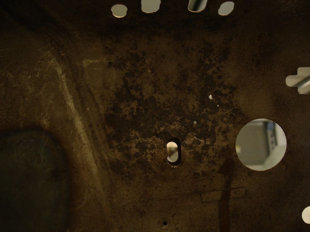
Next bad spot is the area under the brake master cylinder, where the pedal box bolts to. There are cracks and pin-holes galore.

A little aside...

It is now 5 years since I put silicone DOT5 fluid in my TR3A. In all that time, the only issue I had is that the 50 year old stop light switch went out in the first month after the fluid change. BUT!...after that there have been absolutely no problems with the DOT 5 fluid in the car. I am sold. If for no other reason, just for the fact that the silicone does not rot away paint...steel...aluminum....seals...carpet. In this TR2, it was approaching the point where the pedal box was about to punch right through the rotted out tub!

Moving on...


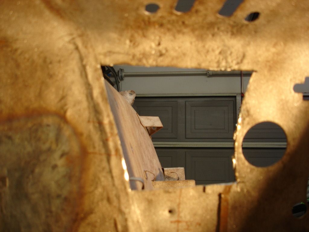
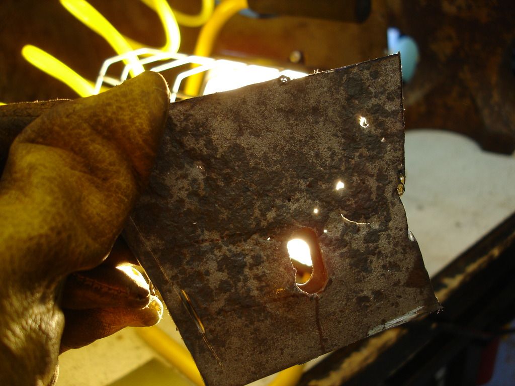
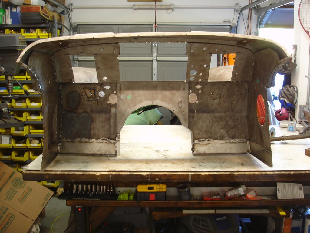
Here I have cut out the bad area. See how pretty it shines light through metal!


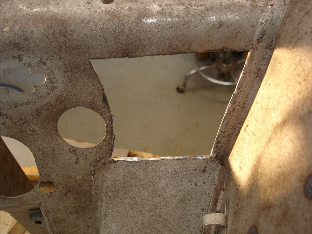
Same cutout from the front. Notice I chose not to mess with the large hole, and instead cut around it. Laziness...the mother of invention. Also...2 of the edges are matched to factory welds on the front of the firewall. These are the welds holding the inner wing to the firewall.


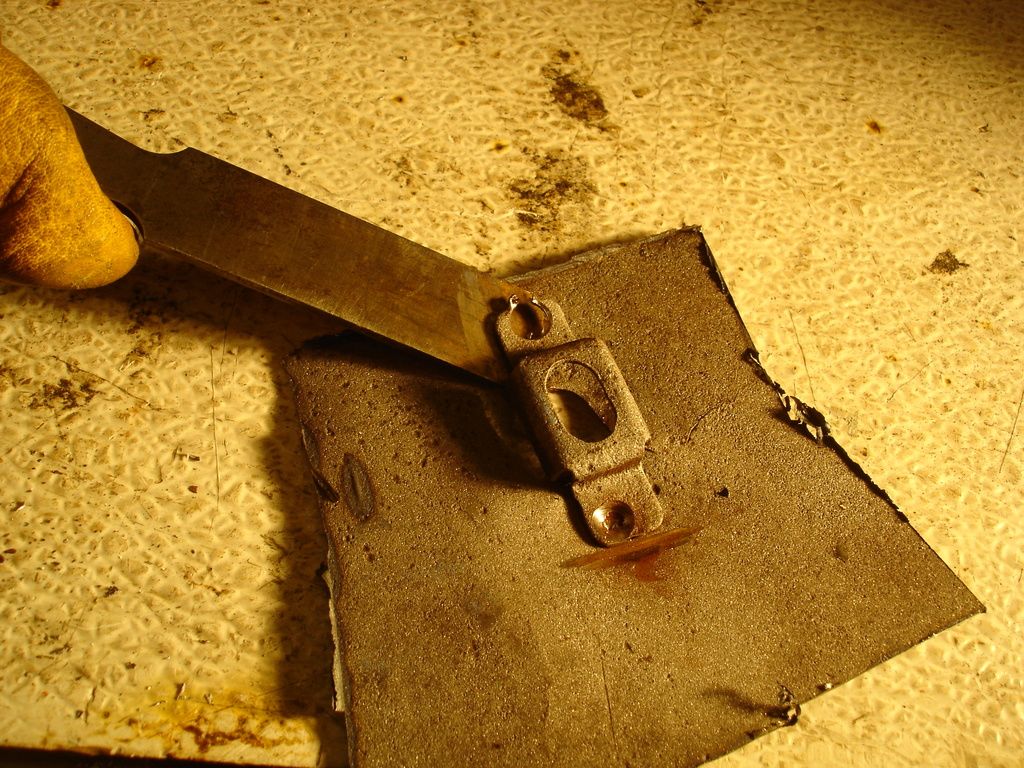
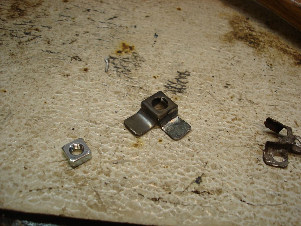
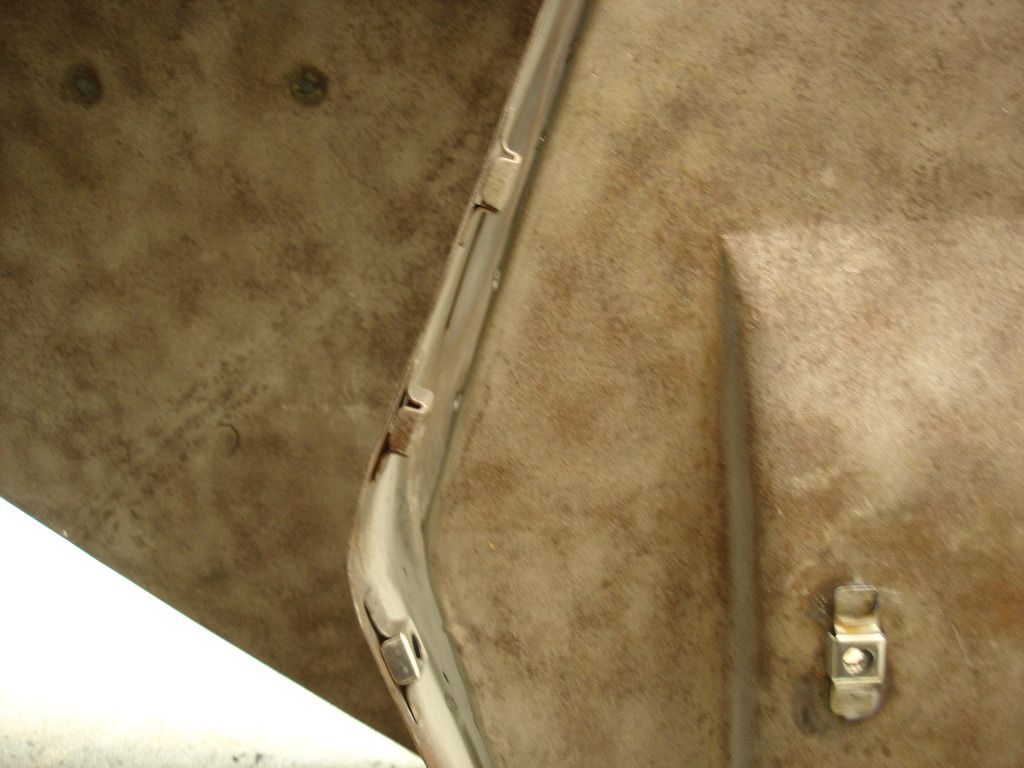
Here is the captured nut that holds the bottom of the pedal box assembly. The nut is gone, and I plan to re-use the cage, so it comes off.


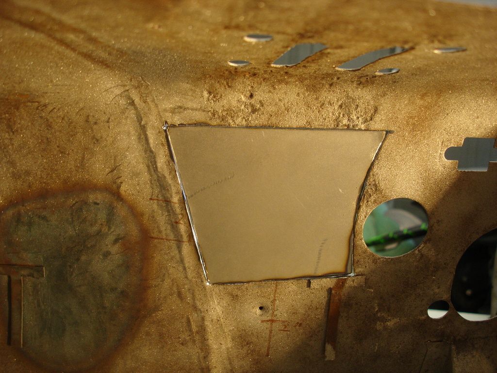
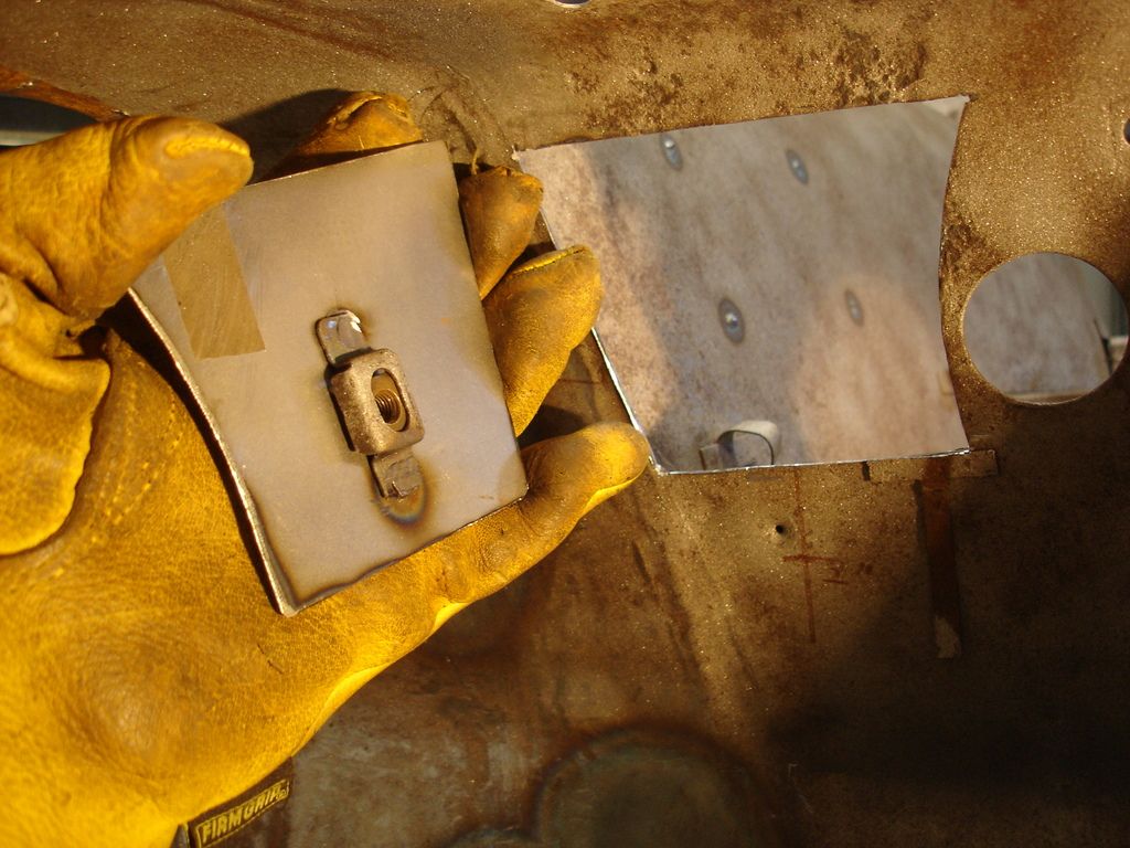
Here is the patch in place. All I did was hold the new metal up to the hole and scribe the shape...then cut it out with shears.


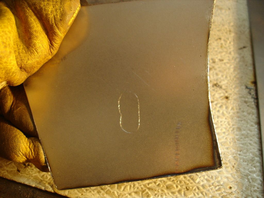
Here I am scribing the location of the pedal nut from the old piece to the new patch.


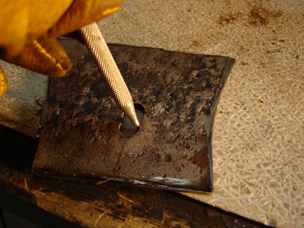
I cut out the oblong hole using first a drill, and then opening it hole to shape with a carbide bit in a die grinder. Then I installed the new nut and old cage. Easier to do it now, before installing the patch in the tub.


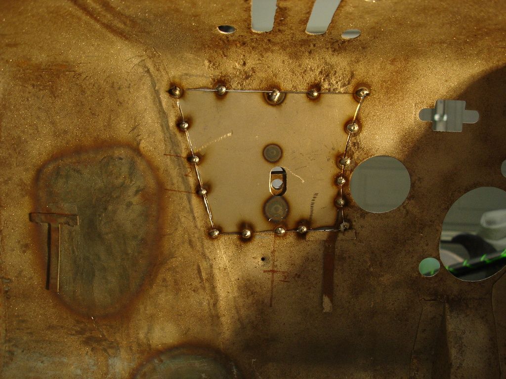
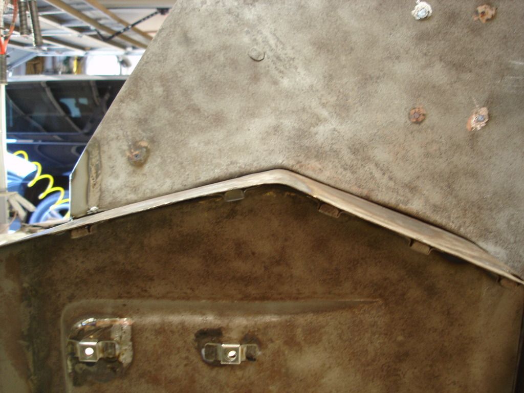
Tacked...welded...and ground.


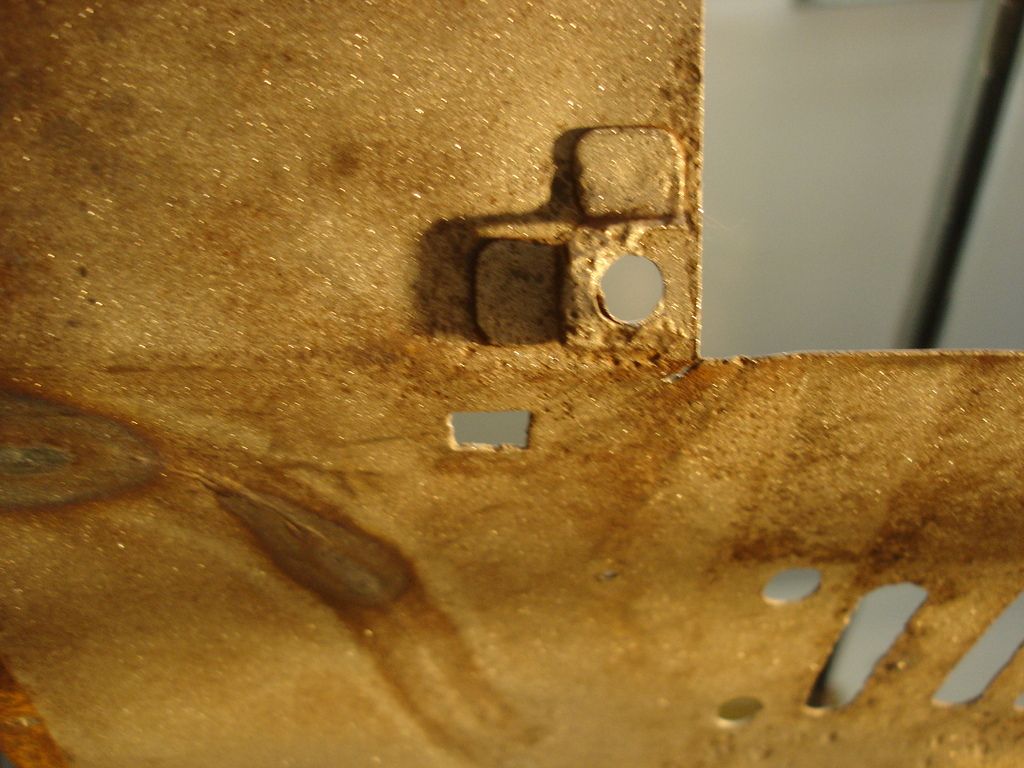
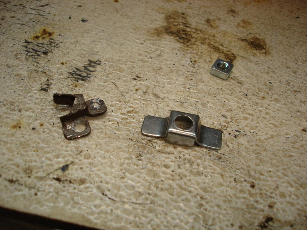
Here's one you don't see in the later cars...look at that 90 degree cage! Neat! Oh, no, wait, I have to duplicate that, so it's not neat at all!

I'll start with a standard cage and modify it by cutting off one tab and re-welding it back on at 90 degrees. The trouble I go through being annul.


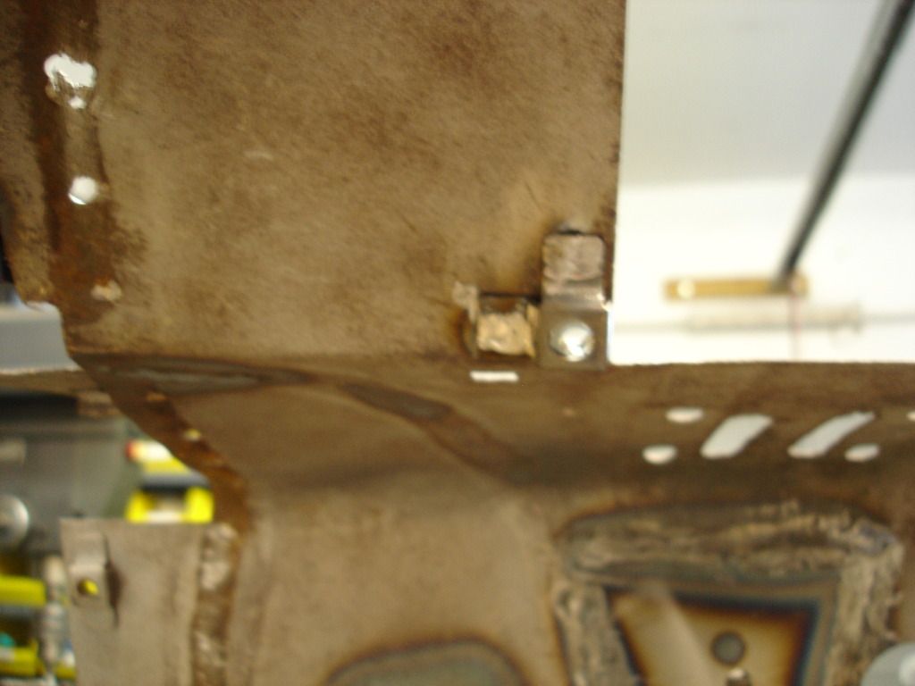
Just like the factory! (well, except for the hole weld instead of a spot weld!?!


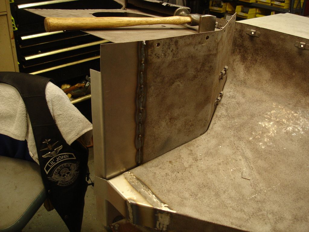
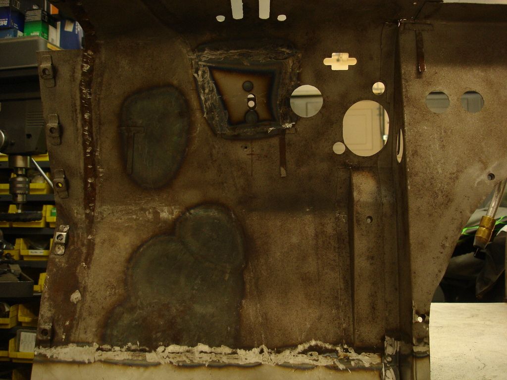
At this point I have done all that I can to the driver side firewall and scuttle, so it's time to re-install the kick panel.

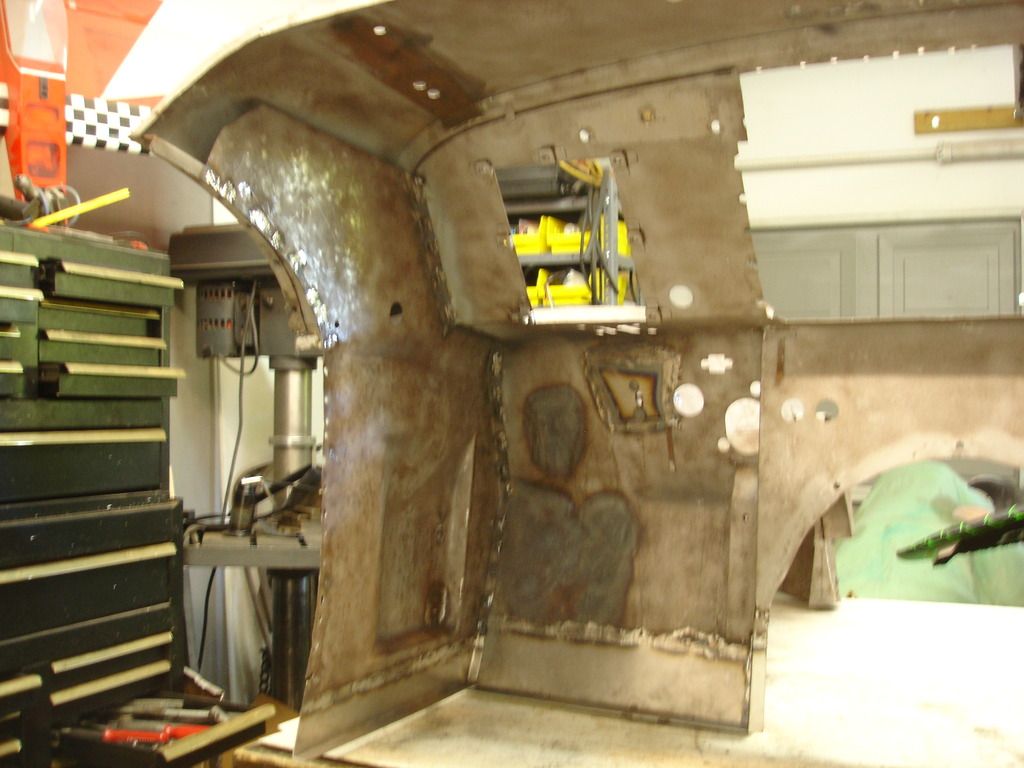
I figured this would be easy, but it turned out (like almost everything else I touch) not to be. If you remember the extent of the impact damage, I should have known that there was no way this panel would fit perfect the first time around.


Here is the issue. The firewall was so heavily dented that it is stretched about 1/2" longer than the kick panel. Nope...no typo...1/2"...bummer! I tacked the panel at the scuttle, and then spent all afternoon with a torch, slowly working that 1/2" back into the metal from which it came.


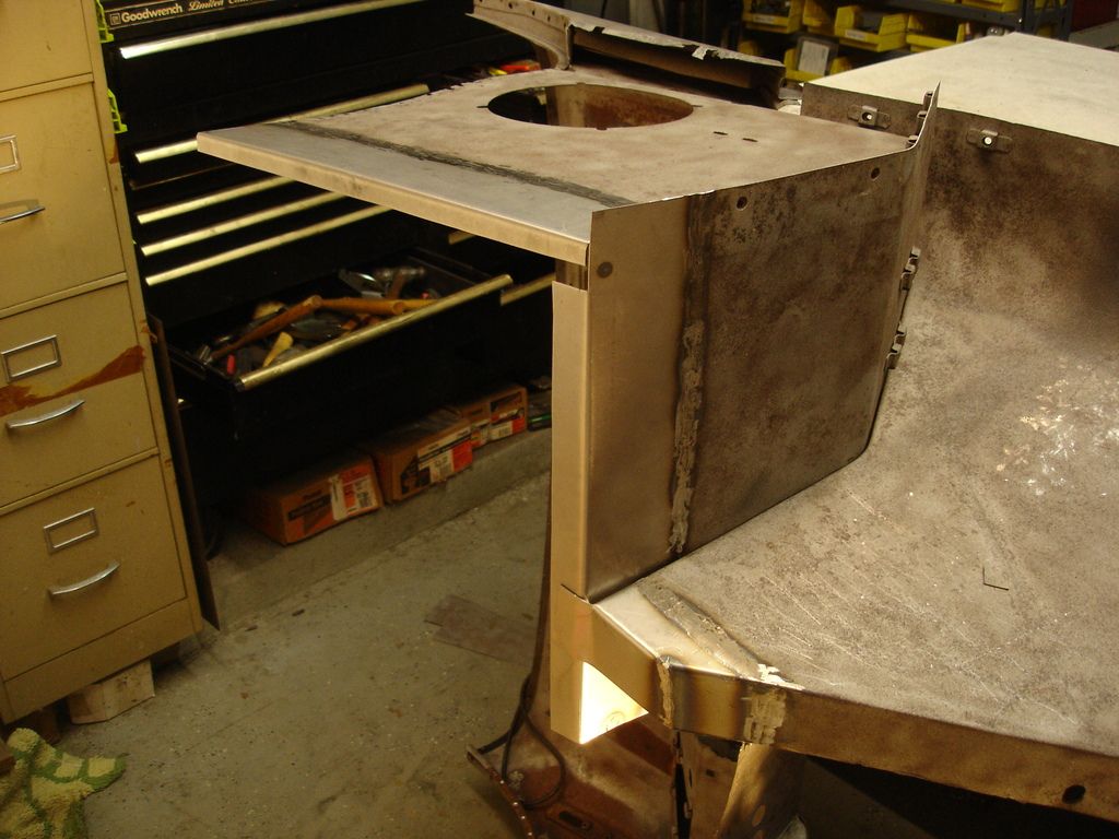
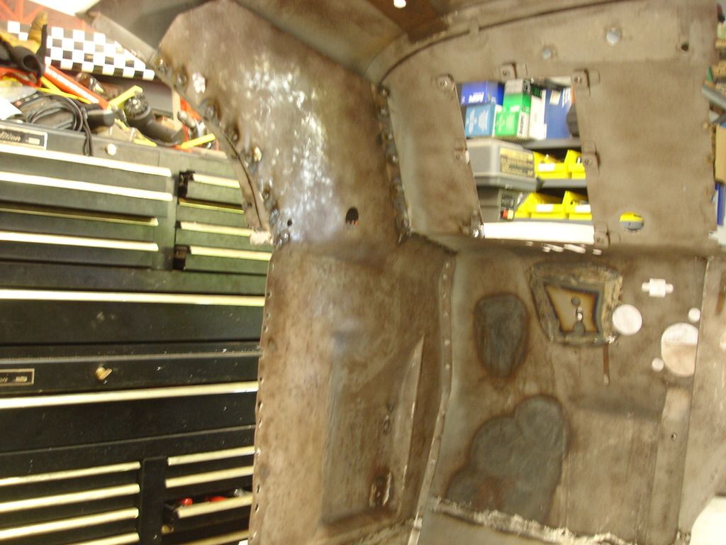
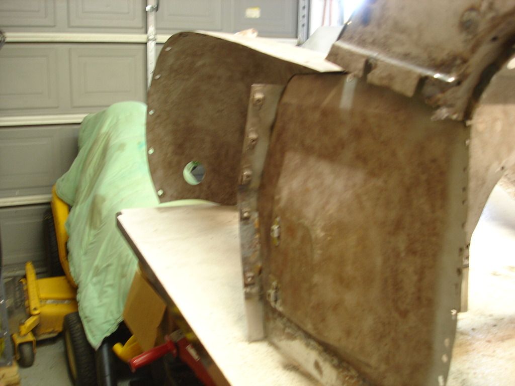
I didn't take the intermediate photos, but this is the result. It fits...hooray!

The chore was a matter of heating a 2" spot red hot and then hammer and dollying it flat. Picking the next spot and repeat, and repeat, and repeat...and ....repeat...and...

But, the end is worth the work. In hind sight it would have behooven me (spell checker says that's not a real word, but I don't care) to use the kick panel as a pattern as I originally worked the firewall. I still got to the finish, but it would have saved time to work it with a pattern. No hindsight in bodywork...it'll drive you crazy thinking about how you could have done it better/faster.


And...once again...another week comes to an end...merely opening up the possibility of even more work for next week. It seems there is no shortage of work.
 
Fantastic work, great explanation of it. Thanks for taking the time to document what you are doing, I am really enjoying watching your progress.
 
Way to Go! Wonder if TRA will add those 'Mickey Mouse' (ear) cages to the judging book...maybe it's already in there?

Jeff
 
John.

I have a question & would appreciate your thoughts.

I'm the 2nd owner of a '59 TR3A (nice survivor). The bulk of the visible rust is on the forward portion of the driver's side floor pan & where this floor pan meets the kick panel (Typical location?).

Would it make sense to make the 3" wide replacement panel from 304 SST instead of carbon steel?

As part of my inspection & mechanical restoration process (SST brake lines, etc.), I will be removing the tub from the chassis.

I have a local certified welder (& fabber) who told me welding carbon steel to stainless steel is no problem. He works mostly with ss.

I'm I missing something? Is it overkill?

BTW, your excellent photos & detailed documentation are greatly appreciated & are inspiring.

Thanks,

mgf
 
I used mild steel for all my repairs. I cut cardboard patterns, then fitted in the new sheet metal patches and MIG welded them with butt joints which I ground flat and smooth. That was in 1988 and now with a further 114,000 miles on my 1958 TR3A, The paint is still like new.

Don Elliott, Original Owner, TS 27489 LO. I bought it brand new in May 1958 here in Montreal and it is now 58 years old. Just like new. NO ! Better that new !
 

Attachments

  • 2014 TR3A 1 4by6 m.jpg
    2014 TR3A 1 4by6 m.jpg
    88.2 KB · Views: 100
  • IMG_6514m.jpg
    IMG_6514m.jpg
    90.7 KB · Views: 96
Back
Top