• Hey there Guest!
    If you enjoy BCF and find our forum a useful resource, if you appreciate not having ads pop up all over the place and you want to ensure we can stay online - Please consider supporting with an "optional" low-cost annual subscription.
    **Upgrade Now**
    (PS: Subscribers don't see this UGLY banner)
Tips
Tips

TR2/3/3A Alternator feedback

TexasKnucklehead

Jedi Knight
Country flag
Offline
Generally when I find something to not be working as I expect, all I need to fix it, is to figure out how I caused it.

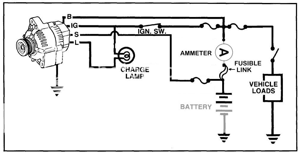
I have replaced my generator with an alternator. It came with no documentation. The alternator has three connections for wires (it is grounded via the frame). The largest connection is threaded and denoted "B". I assume this to be the output and it is connected to the Battery (actually the NU/brn-blue wires at the voltage regulator). Two spade connections are grouped, one horizontal and one vertical to accept a connector that could not be installed disoriented. I don't have the mating connector, but 2 spade lugs fit well. Above the connector is marked "IG". I have "IG" wired to a switched hot (ran a white wire to the fused side of the white/green terminals on the fuse block). The other spade connector is connected to the small yellow wire that goes to the idiot light on the dash.

When I turn on the key, the idiot light lights, dimly. The ammeter shows discharge with anything switched on, without the engine running. The ammeter needle moves towards +30 amps as soon as the car starts (it's a 30a alternator) and slowly declines towards "0", never really reaching it. After started, the idiot light gets brighter with the engine revved. It dims as the amp needle goes towards 0 -but the idiot light does not ever go out.

How can I make the idiot light go out?

At first I thought the "IG" was for the idiot light, and I wired it to that, and tied the other spade to B, thinking the 2nd spade was intended to be "Sense". -The idiot light never came on, but the alternator charged. Also, I noted a 1/2 amp discharge with the "Sense" hot wired to B with the engine not running and key off. So I changed it to as above.

The original regulator is still in place, but the F and D terminals have no connections. So it should be acting like a junction box for the used wires (only between A and A1 -even when all three NW+NU+Y are tied together).

Suggestions are welcome.
 

TR3driver

Great Pumpkin - R.I.P
Offline
IG should get power only when the ignition is on. I'm guessing the other terminal is for the warning light and there is no 'sense' terminal.

Here's an old cheat sheet that seems to usually be accurate

alternator_connections.jpg~original
 
Last edited:

TR3driver

Great Pumpkin - R.I.P
Offline
Randall, I can't see the cheat sheet. Is it my computer?

Thom
1959 TR3
#TS34909L(O)
Try it now, maybe a JPG will work better than the GIF I posted before. You may have to hit refresh in your browser.
 

CJD

Yoda
Country flag
Offline
Glad to hear you're going the alternator route with all the generators you've gone through!

Is there a chance the other side of the idiot light is meant to go to +12v instead of ground?
 

TR3driver

Great Pumpkin - R.I.P
Offline
Is there a chance the other side of the idiot light is meant to go to +12v instead of ground?
Should always go to switched hot (white wire) just like the original generator setup.
 

CJD

Yoda
Country flag
Offline
Should always go to switched hot (white wire) just like the original generator setup.

I'm referring to the second wire going to the actual idiot light. Yellow from alt to light, then second side of light to ground or hot?
 
OP
T

TexasKnucklehead

Jedi Knight
Country flag
Offline
Randall, thanks for that, I could see it well. (I've already seen the light.)


John, the second wire does feed the light, and the other side of the light goes to switched power. I considered the notion of the regulator using the power input (IG) as a reference, and sourcing current, rather than sinking it, to illuminate the bulb. So, I put a spade lug on one end of a wire with a bulb on the other end and grounded the bulb. With the spade inserted into the non IG alternator spade, and the key on, the bulb doesn't light up. Although that approach technically would solve the problem (the idiot light would no longer be lit), I don't think it would ever light -which kind of defeats the purpose of an indicator light.

Shawn, thanks for the link -I hadn't seen that particular video. It didn't really answer my questions, though, because it assumes a 2 wire alternator. My biggest issue was determining exactly what alternator I have, and how to specifically wire it.

During my tribulations, I may have found part of my problem. I often pull the negative terminal off the battery before messing with wires, and I noticed that occasionally I would have no power at the white wire when I turned on the key -after the negative terminal was placed back on. It seemed anything I touched, would result in a "fixed" condition. This morning the white wire had no power (again) and I carefully investigated. It turns out the screw to hold the NU wire to the back of the ignition switch was loose. I believe this was a ressistive connection, providing -in my case- a lower voltage to the green wire where I was feeding the IG terminal of the alternator.

In any case, the idiot light is still on, but barely. The alternator is providing power and charging the battery. The ammeter seems to be indicating as expected. The battery has no current draw with the key off. At idle with nothing turned on, the ammeter is at 0 with the battery voltage barely over 13v. I think to have better performance, I'd need to use a smaller pulley on the alternator (instead of the original generator pulley), but I expect the present situation to last longer than any of my generators have lasted. I still wish the idiot light was not on at all...
 

TR3driver

Great Pumpkin - R.I.P
Offline
I'm referring to the second wire going to the actual idiot light. Yellow from alt to light, then second side of light to ground or hot?

Perhaps this will make it clearer. This is a hacked-up Toyota drawing that shows the third 'sense' wire; you can just ignore that in this particular case.

Denso%20alternator%20wiring%20diagram_1.jpg~original
 

TR3driver

Great Pumpkin - R.I.P
Offline
Still not showing on my ipad unfortunately. Others now seeing? Cheers, Mike
Sorry about that; not sure what else to try. Shows fine for me, but I don't have an ipad. I'll try to check with the wife's ipad, later tonight when we're both home.
 

TR4nut

Yoda
Country flag
Offline
Ive been trying to read up on this as there are a few forums out there that talk of similar difficulties with the NipponDenso/denso clone alternators. Would it make sense to put a diode in the lamp circuit? Basically when the alternator is not charging the current grounds through the light into the alternator. When the alternator charges, the output is higher than battery voltage and you get a reverse current that dimly lights the warning lamp - if that's not flawed, wouldn't a diode cut off that reverse flow and let the lamp go out?
 

TR3driver

Great Pumpkin - R.I.P
Offline
Ive been trying to read up on this as there are a few forums out there that talk of similar difficulties with the NipponDenso/denso clone alternators. Would it make sense to put a diode in the lamp circuit? Basically when the alternator is not charging the current grounds through the light into the alternator. When the alternator charges, the output is higher than battery voltage and you get a reverse current that dimly lights the warning lamp - if that's not flawed, wouldn't a diode cut off that reverse flow and let the lamp go out?
IF that is the problem, then the diode would fix it. But the lamp output from the alternator is at best a sample of it's output voltage. I would be more interested in how the alternator output voltage is enough higher than the ignition circuit voltage to light a lamp that takes at least a volt or two to even glow. (Actually, the internal diagram I have for a Toyota/Denso alternator shows the lamp signal with a push/pull drive; and the high side comes from the IG terminal. So in that case, I'd look at why the lamp source is higher than IG, which should be the same.)
In other words, the real problem (aka root cause) is not the reverse current through the lamp, but the bad connections/poor contacts/etc that are causing the ignition circuit voltage to be significantly lower than the battery voltage.

But as I understand it, he's got the lamp wired to the IG terminal, which is simply wrong. Adding a diode isn't going to fix that. The IG terminal supplies power to the internal regulator circuitry, only while the key is on.
 
OP
T

TexasKnucklehead

Jedi Knight
Country flag
Offline
Let me explain. At first I did have the lamp wired incorrectly, which Randy was quick to point out to me. (I could have used that sheet with the pin-outs a little earlier too.) After correcting that, I found the loose screw and things started to look better. The light was still on, but not very bright. It would get brighter/dimmer with engine RPMs. After a 120 mile test drive today with speeds in excess of 70mph, it all seemed much better. When in the sun, the light is too dim to notice -just like the turn signal indicator light. Now that it's back in the garage, I can barely see it's on, so I'm thinking my battery was a little low as well.

For what it's worth, I read on-line somewhere that a diode might be needed to prevent back flow from the internal regulator, after the alternator was producing, providing power and keeping the engine running after the switch was shut off. I have removed the diode. If the light is to illuminate because of either the alternator or battery voltage getting low, the diode will not work.

In any case, it all seems to be working fine now. I did have some poor and dirty electrical connections, but I really think the culprit was (after proper connections) 1)poor connection at the ignition switch and 2)low battery.

Thanks for all the help.
Jer
 

mgedit

Jedi Knight
Country flag
Offline
Sorry about that; not sure what else to try. Shows fine for me, but I don't have an ipad. I'll try to check with the wife's ipad, later tonight when we're both home.

Randall, it is showing this morning. Not sure if you fixed it or my ipad is now just cooperating. Thanks, Mike
 

TR3driver

Great Pumpkin - R.I.P
Offline
That's good, because I totally forgot about borrowing the wife's Ipad.
 

M_Pied_Lourd

Darth Vader
Country flag
Offline
Same for me Mike so it's not just you...:smile:


Cheers
Tush
 
Similar threads
Thread starter Title Forum Replies Date
I MGB Alternator help MG 0
P Alternator Installation Pic Austin Healey 4
P Generator to Alternator Swap Austin Healey 2
W Generator or Alternator? Austin Healey 18
Writer2022 GT6 GT6 MK3 Alternator Problem Triumph 4
K TR2/3/3A Is it time for a new alternator??? Triumph 8
M Smog pump and alternator brackets Spridgets 0
V MGB Never occurred to me that my '66 would be positive ground. Does the presence of an alternator show that it's been converted? MG 22
A General MG 78 MG MIDGET ALTERNATOR SMOKES MG 5
E MGB external alternator regulator MG 2
DrEntropy MGB Generator to alternator swap MG 1
M TR2/3/3A Generator Warning Light on with the Alternator Charging the Battery Triumph 4
K TR2/3/3A Overtightening the alternator belt? Triumph 14
B TR6 Swapped Lucas to GM alternator Triumph 9
M TR6 Alternator Issue for 72 TR6 Triumph 7
K TR2/3/3A Can anyone confirm that if you replace the ammeter with a voltmeter ( generator removed and alternator added) that you...... Triumph 5
K TR2/3/3A British Wiring alternator conversion kit question. Triumph 3
K TR2/3/3A Red ignition light stays on...car has alternator not generator. Triumph 17
K TR2/3/3A TR3 with alternator conversion... red light stays on and low voltage on the voltmeter gauge? Triumph 1
G Spitfire Alternator troubles Triumph 2
jehuie Help...replaced my alternator and now my water pump is leaking. Spridgets 16
TheRealDestrux MGB Unknown connector on alternator MG 6
R TR2/3/3A Amp Gauge-erratic reading after alternator conversion Triumph 39
lilifer_13 Spitfire New alternator doesn't fit - '78 Spit Triumph 2
AUSMHLY Generator to Alternator Swap Austin Healey 20
J TR6 1975 TR6 Alternator Advance/Retard spring(s) Triumph 1
Lin Fan belt for 1275 with alternator Spridgets 4
PAUL161 T-Series Dynamator Alternator conversion. MG 23
P '58 XK150 Dynalite Alternator swap question Jaguar 5
B Delayed charging Lucas alternator Triumph 1
Merlin63Tr4 TR4/4A Alternator or alternator in a generator case? Triumph 4
Walter74 Dynamo to alternator Austin Healey 2
S Stag Lucas 18ACR alternator conversion Triumph 5
Got_All_4 TR5/TR250 Rebuilt Bosch Alternator stops charging Triumph 0
donbmw TR2/3/3A Converted to alternator Triumph 14
90dog A H Spares Alternator Bracket Austin Healey 53
R TR2/3/3A generator to alternator Triumph 5
JPSmit Alternator help - please. Spridgets 21
I Bugeye generator/alternator conversion question Spridgets 7
Ripper01 TR6 110A Alternator Triumph 7
F TR2/3/3A I'm stuck... alternator/wiring/starting/? Triumph 2
Sopwith_Camel alternator eater Spridgets 20
longbridgehealey Alternator conversion and tach Austin Healey 9
S TR2/3/3A Alternator Triumph 7
apbos Positive Ground Alternator wiring. Spridgets 9
BoyRacer Wiring question for alternator conversion Austin Healey 3
RAC68 How does a 12 Volt Alternator charge a battery to read 18+ Volts Austin Healey 8
M TR2/3/3A Water Pump Belt After Alternator Conversion Triumph 6
J MGC Lucas alternator/regulator MG 3
K TR2/3/3A Revington alternator heat shield. Triumph 0

Similar threads

Top