• Hi Guest!
    You can help ensure that British Car Forum (BCF) continues to provide a great place to engage in the British car hobby! If you find BCF a beneficial community, please consider supporting our efforts with a subscription.

    There are some perks with a member upgrade!
    **Upgrade Now**
    (PS: Subscribers don't see this gawd-aweful banner
Tips
Tips

Wheel Tire Camber

AUSMHLY

Yoda
Country flag
Offline
Wheel Camber

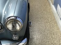
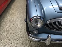
Noticed all 4 wheels have a bit of tilt, camber (if that's the correct word)
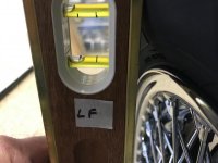
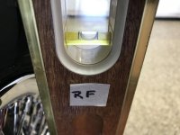
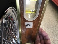
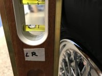
I put a level, pressed against tire, vertically on them. Here's where the bubble is on each tire. Only the Passenger Right Front "RF" has the bubble in the middle.
Should all wheels be vertically straight, or is some camber acceptable? How do I correct that?
Not easy to see in this photo, but the driver Left Front "LF" has the worst camber.

Car drives straight, steering wheel is centered, no excessive inner or outer wear on any tires. No scuttle shake...thank goodness.
IMG_1857.jpgIMG_1856.jpgIMG_1852.jpgIMG_1851.jpgIMG_1850.jpgIMG_1849.jpg
 
First off, you have to measure the slope of the floor you measured on; it likely has some slope and probably isn't perfectly flat. Assuming it is flat and level, your LF has a bit of negative camber, the RF is 0deg and the rears, well, you can't do much about them anyway. The nominal setting, per the book, is 1deg positive, but alignment guys tell me that 0deg with a little bit of toe-in is best when running radial tires. You can change the camber a teeny bit with offset bushings, but if your car tracks true and doesn't inordinately wear the tires on one side I wouldn't worry about it.

My BJ8 always had 2deg or more pos. camber in front; subsequently the outside of the tires wear quicker than the inside (my driving habits couldn't possibly have anything to do with it ;)). My BN2 came with excessive negative camber, we never figured out why and the frame seemed straight as far as we could tell. We installed the adjustable shock plates from Kilmartin--got two of the defective ones--and have it set at about 1deg+; it drives and handles fine and I have other issues to attend to before worrying about that.
 
Not that this is totally accurate but a home method to rough check the camber...
first: make sure on a level surface;
Second: push the car forward to a spot not letting it roll back;
then: get a stand or chair or something taller than the tire. hang a plumb bob from it. when it all quits swaying, measure in to the top of the wheel (inside the edge bead) and measure in to the bottom of the wheel (same place).

of course it would be a good idea to have the toe-in set properly before you start.

Or even better yet, take it to a shop. there are shops around here that check alignment for free.
 
Car drives straight, steering wheel is centered, no excessive inner or outer wear on any tires. No scuttle shake...thank goodness.
Ausumly:
Let it alone or do as drone dog said take it to a shop.
 
Last edited:
Danny and Drone Dog are right, you should not use the tire to measure against (how are you accommodating the 'bulge' at the bottom). As Drone Dog said, measure to the rim at the tire bead area and ignore the tire itself.
An alternative to Drone Dogs method is to make a rigid jig that can seat on the rim and extends far enough out to allow you to use a level that clears the hub and tire.
Dave
 
Danny and Drone Dog are right, you should not use the tire to measure against (how are you accommodating the 'bulge' at the bottom). As Drone Dog said, measure to the rim at the tire bead area and ignore the tire itself.
An alternative to Drone Dogs method is to make a rigid jig that can seat on the rim and extends out far enough out to allow you to use a level that clears the hub and tire.
Dave

As usual, it's a learn as you go.
Ah, the rim method, genius :smile:
Thanks guys.
 
Danny and Drone Dog are right, you should not use the tire to measure against (how are you accommodating the 'bulge' at the bottom). As Drone Dog said, measure to the rim at the tire bead area and ignore the tire itself.
An alternative to Drone Dogs method is to make a rigid jig that can seat on the rim and extends far enough out to allow you to use a level that clears the hub and tire.
Dave

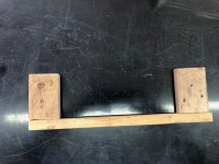
Here's the complex, highly-engineered tool my dad made:

Camber Tool.JPG
 
Bob - you got drawings for that tool???
We had the top of our shock towers replaced with the adjustable magic camber plates and the alignment shop wasn't able to get the exact camber/toe-in/bells/whistles adjusted even with this installed.
I am most definitely not complaining, as a lot of retrofit such as this is a best guess/hope&pray operation, even with the best tools and intentions available.
We might be getting some accelerated tyre wear, but the shop advised that the adjustable plates combined with the Udo Putzke Bilsteins had provided the best ride/handling combination that they'd ever had. Doug

Sorry, the Defense Department made me destroy all documents after we finished the project.

Why did the shop have so much trouble with the adjustable plates? Were they the Kilmartin ones or Tom Monaco's or ?.
 
I too used a highly engineered tool such as the one Bob has shown. Although I made it from a piece of aluminium bar and two small blocks. It is designed so that the blocks sit on the inside of the wheel bead thus avoiding the tire bulge. Instead of a typical level held against the aluminium bar to see an angle I used a swinging arm protractor to read the actual degree from vertical.
 
The camber adjustment was just a comment - I didn't worry about it as they were satisfied with the end result. I'd purchased the plates from a private owner and don't recollect the original source. I wasn't around when they installed the plates (the shop was really good about encouraging their customers to stop by) and I wasn't smart enough at the time to ask how it had gone. Doug
 
Hi All,

Note.
Originally this post was stated to be able to secure Caster in error and was updated to correctly state the fixtures were designed to secure Toe measurements. Sorry for the original error.


A while back we were discussing wheel alignment and I created a wheel fixture that allowed me to make consistent Toe measurements and camber measurements, The wheel fixtures are held onto the rims with hoods on the spokes to secure their position. In the horizontal position, caster measurements can be taken in front and back of the wheels. Set the fixture extension vertically with a Level, and a O-degree camber setting can be made with the same Level. Each of the 2 fixtures was constructed with scrap material but with the purchase of new hooks.

Alignment Fixture.jpg
Alignment Fixture 2.jpg


I used it once and It worked perfectly, to date,
Ray(64BJ8P1)
 
Last edited:
Hi John,

Note: the description below was how the previously posted fixture was used to get consistent Toe measurements and not Caster. Sorry for the error.

Using 2 tape measures, 1 in front and one behind the wheel, placed the 2 tapes through the lower slits, anchored on 1 side (i.e. driver side fixture) and read both at the other (passenger) side after passing through the lower slits on the other fixture. This will give you the 2 measurements needed to determine the Caster.

Keep in mind that the outer portion of the fixture, with the slots, comes close to the ground but does not touch the ground. This results in no interference of the ground and allows it to float with positional dependence only on the wheel. As a result, Caster measurements and adjustments can be made with both wheels in the air, followed by validation of adjustment on the ground.

Although I only used it once, some time later I had the alignment done by a friend with a optical rack and he indicated that no adjustment to Caster was needed. I guess the fixtures worked good.

Ray(64BJ8P1)
 
Last edited:
Ray, your description of measuring from wheel to wheel via the tape measure and the slots sounds more to me to be measuring toe-in or toe-out. Caster, which is the inclination fore and aft of the swivel pin (kingpin to many Americans) is non-adjustable on a Healey as it is on most vintage English sports cars. The caster is designed into the configuration of the frame, the lever arm shock, and the pick-up points of the lower A-arm.
 
I think the TSM states the camber is pre-set at +1 deg. The camber bushings that Moss sells actually work pretty good . I have Mine set between 0 and -.25
 
Hi All,

Sorry, you are all correct. I did describe Toe measurement and not Caster. A hopefully temporary Senior Moment.

Thanks for the correction,
Ray(64BJ8P1)
 
Last edited:
Back
Top