Offline
[ QUOTE ]
Hello Dave,
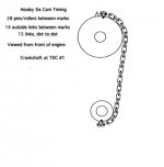
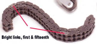
that's life, I did mention in one post it only worked for symetrical timing. I also said that it is not the normal way to time but it is a very easy check and will indicate, even with assymetric timing if you have a serious valve timing issue or not.
As for different ways of marking the valve train for assembly, I once owned a car which had no markings at all. Valve timing was done on valve lift with a dial indicator at TDC.
Alec
[/ QUOTE ]
Hi Alec,
I've "built" quite a few performance auto & motorcycle engines over the years. All had non-standard cams & required adjustable sprockets, gears, or offset keys to dial in with your dial indicator & degree wheel. I degree ALL valve opening & closing events. For maximum performance, the cam or cams should be within two degrees of the intended timing. Obviously, cam timing must be tailored to the rest of the engine design/modification. For example, turbo charged engines can benefit greatly from earlier intake opening & closing events.
A really fun engine to work with is the old Triumph motorcycles. I still have one. They have separate intake & exhaust cams, much like the Jags, that can be tailored to whatever intake & exhaust timing are desired for the particular engine's combination of parts & intended usage. With a combination of three cam keyways & the ability to advance or retard a gear tooth or two, there is almost infinite adjustment ability. To top it off, there were two different cam follower radiuses available which allowed tailoring of valve opening & closing rates.
On many engines, for a given cam design, the intake valve closing point will have the single greatest affect on the engines power band characteristics & the entire cam (all events) can be advanced or retarded to suit.
Port controlled two stroke engines are a whole different game, but still fun to work with.
I think we generally agree, counting links on a chain is a pretty crude way of setting cam timing, & I doubt that the serious performance engine builders relied upon it. Factory settings were a compromise to work with the intended combination of engine components, for the greatest number of drivers. It might well be that the Healeys under discussion could benefit from non standard cam timing with certain combinations of engine modifications. The original chosen timing may have been decided by inherent port flow restrictions.
Aside: At one time many engines had the intake valve closing delayed to reduce cylinder pressures & NOX emissions. They also had TDC overlap reduced to lower Hydrocarbon emissions at idle.
To one person a "serious issue" would be timing that was 10 degrees off. Another would consider more than two degrees off to be unacceptable. A third person might wish to rearrange the whole thing.
Regards,
D

 Hi Guest!

 smilie in place of the real @
 Pretty Please - add it to our Events forum(s) and add to the calendar! >>


