71TR6
Jedi Hopeful
Offline
Well, after a delay working on the TR3 for a number of personal reasons, I finally found a frame guy that was willing to schedule the work (as opposed to "check back with me in a month or so"). I picked up the straightened frame earlier this week and he confirmed the shock tower was twisted and pushed in along with the frame. He was able to pull everything back into proper position (within 1/16" he says).
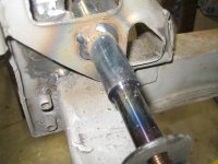
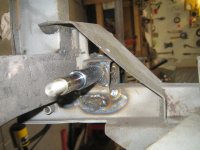
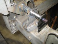
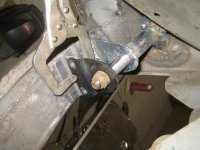
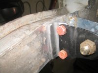
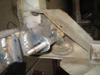
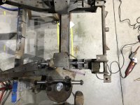
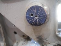
Yesterday I spent 3 hours removing the damaged lower fulcrum pin. I opted to drill the sucker out. After cutting the outboard brackets off, I took a sawzall to shorten the stubs to about 1/4" from the shock tower bracket. A little dykem and a center square allowed me to center punch the center on each end. On the forward part, space was VERY limited so I stubbed a 1/8" bit to 1 1/4" long and used an angle drill to place the pilot hole. I used a conventional 1/8" jobber bit on the other end and then switched to a 6" jobber bit to go all the way through. As you can see from the picture, I was close but not centered. The next pass was with a 1/4" bit that I biased to one side to hit closer to center on the front end. As you can see, it seemed to work. From there on I just stepped up with drill bits until I got to the final 7/8" diameter. I did need to do a little work with grinding burr to clean things up but I turned out fairly well. I didn't have a 3/8" chuck in my corded drill so I had to use my cordless and it really pushed the Porter Cable cordless to the limit. I had to stop a couple of times for the drill to cool when spinning the larger bits when the windings started to smoke. I've attached pictures so you can follow the sequence.
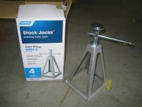
Next I'll be setting the frame up on jacks to check frame reference positions, making a jig to position the new pin parallel to the frame center line, and then welding the thing in.
Thanks for everyone's guidance!
Ron


 Hi Guest!

 smilie in place of the real @
 Pretty Please - add it to our Events forum(s) and add to the calendar! >>
