• The Roadster Factory Recovery Fund - Friends, as you may have heard, The Roadster Factory, a respected British Car Parts business in PA, suffered a total loss in a fire on Christmas Day. Read about it, discuss or ask questions >> HERE. The Triumph Register of America is sponsoring a fund raiser to help TRF get back on their feet. If you can help, vist >> their GoFundMe page.
  • Hey there Guest!
    If you enjoy BCF and find our forum a useful resource, if you appreciate not having ads pop up all over the place and you want to ensure we can stay online - Please consider supporting with an "optional" low-cost annual subscription.
    **Upgrade Now**
    (PS: Subscribers don't see this UGLY banner)
Tips
Tips

TR2/3/3A Right Front Suspension Damage Repair?

sp53

Yoda
Country flag
Offline
Yes safety first always, you are a 100% correct on that one Frank. The safety issue is why I wondered if even trying to straighten the pin was ok. Moreover, I have not even seen the pin or the surrounding area or tried to straighten one out. Personally, I am kinda of a gambler and looking to probability and odds. Just driving a tr3 is really not too smart, and I have done that for over 45 years, knock on wood, and that might show in my personality. Plus I have high regard for the talents of a good welder.

Let me ask this what if question. If the pin did shear off, what would most likely happen (back to odds). I am thinking the car would drop down and I am thinking the steering would work and the other parts of the suspension would stay in tacked. I am guessing a broken tie rod or brake hose might be worse. Just being the devil advocate here Frank. I have learned a lot for you and others on the forum.

steve
 

CJD

Yoda
Country flag
Offline
I personally would not worry about bending it back. To loose the arm, both ends of the pin would have to fail, and based on the oversize of the pin, I can't visualize a situation when that would happen. Picture the diameter of the pin compared to the diameter of the stub axle and you can picture what I mean. The stub axle is barely larger, and it takes all of the road loads, whereas the pin shares the same load between 2 ends of the pin and the upper ball joint. The pin even has an insurance policy with the outside brackets...while the stub axle has nothing but a single nut to hold it together.

I am waiting to hear the results of the drilling, as I have serious doubts that it could work. Even if you find perfect center on a bent pin using 1/4", 3/8" and 1/2" bits...if you are even 1/10 of a degree off on the final 5/8" bit, then the drill will skip out of center inside the tower, with no leverage to re-center it. It will leave old welded pin material that will prevent sliding a new pin into place...and assuming it does, that drill misalignment will be carried to the new pin. So after the operation, the best you could hope for is a new crooked pin. Drilling is a "hail marry" at best, at least in my opinion. I base that mainly on the fact I have never heard of it being accomplished successfully.

Everyone knows I am am absolutely annul in a restoration. Still, my order of tackling this would be in an order of escalation:

1) Attempt to bend back into alignment.
2) Possibly attempt drilling...although I personally know my limitations and would skip this.
3) Look for a replacement tower that I could easily weld into place.
4) If none of the above was an option, or they failed, then I would open up the tower to replace the current pin assembly.
 

Frank Canale

Jedi Warrior
Silver
Country flag
Offline
I have suggested bending the pin repair, I have suggested sacrificing the pin buy cutting and drilling, and a last resort of removing the tower. I know I could accomplish this using any of the methods but it is not my call. I will support Ron's decision because he is there and he knows what tools and skill level he has at his disposal. He also has to be comfortable with the out come. I was told to scrap my frame and tho not the smartest decision I do not regret one minute that I spent repairing my frame. Frank
 

sp53

Yoda
Country flag
Offline
Frank I feel I put you in the hot seat as a technical adviser. You would be the guy I would want on board fixing my car. Plus you are a kind and helpful man. Heck in the past on this forum we had some challenging dialectical debates on how to fix something. I trust, I did not cause you any discomfort by my novice opinion on welding and repairing items beyond my scope. Moreover, I love that bracket you made me. Anyways, I will enjoy following this post.
steve
 

Frank Canale

Jedi Warrior
Silver
Country flag
Offline
No problem, Steve or John. I feel we all agree there are several ways to repair the suspension. Each have pros and cons and all input will help Ron decide which way to proceed. Ron will need all watching and adding suggestions as this repair is a long and winding road. I know that as he gets into it the plan may change and will need suggestions and again we will give our opinion. We will all be right when the suspension is repaired and Ron is back on track with his restoration. On a different note John, I have gone back and reviewed your TR2 restoration. I am struggling with the dog leg quarter panel area. I am amazed at how you and Lionel fearlessly take the tub apart, do your repairs And put it back together. Highest of praise to the work you do. Thank you for the documentation and for your input. Frank
 

CJD

Yoda
Country flag
Offline
I'll likely be doing that quarter dogleg again while helping Joe (busted knuckles). He's a friend who lives about 10 minutes away and just inherited his uncle's TR3. He's still in the disassembly stage, but is working fast towards welding body parts. It's been so long I'll have to review my own thread!?!
 
OP
71TR6

71TR6

Jedi Hopeful
Country flag
Offline
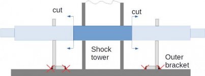
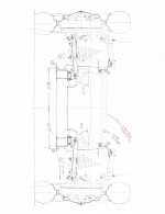
I appreciate everyone's input! This is a great discussion and it is great that everyone is offering options. While I could heat and beat the pins straight, they still would not be in the correct position relative to the upper pivots and will result in messed up camber. Based on the bodged welds on the front and rear outer brackets, there is probably some twist in the positioning that will bugger up the caster as well which is why I'm replacing the pin. I'm not planning to drill the full length of the pins- By cutting the welds on the outer brackets, I can then cut the fulcrum pins off close to the shock tower.
LowerFulcrumMods.jpg

Since I'm replacing the pin, cutting it this way minimizes the depth of drilling I need to do. I then just need to continue to open the diameter until I get to the outer diameter of the fulcrum tube. At least that's what I'm planning....


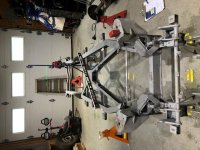
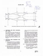
Relative to the frame itself, I've finally finished taking the critical measurements. Here's my setup...
ROns_TR3A_Frame_Measurements_SetupImage.jpg

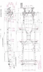
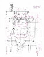
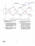
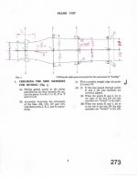
I have to say, it is very difficult taking measurements off this frame to the 1/32" but I'm comfortable that I'm accurate with my dims to the nearest 1/16". Based on my analysis, the top right shock tower is slightly kicked in and the left side of the cross tube is slightly buckled . The lower frame directly under the shock tower is in the correct position (probably due to the lower frame cross member) but the frame at immediate front of the shock tower is kicked in and then comes out (probably since the front is connected with he front cross bar). Behind the shock tower, it is kicked in so it appears the impact and bending of the pins pushed the frame in toward the center through the outboard pin mounts. Slight buckling on the right angled frame member going to the Tshirt confirms this. Here's the results of my measurements...
Rons_TR3A_Frame_Measurements1.jpg Rons_TR3A_Frame_Measurements2.jpgRons_TR3A_Frame_Measurements3.jpg
Rons_TR3A_Frame_Measurements_BentleyFig3.jpgRons_TR3A_Frame_Measurements_BentleyFig4.jpgRons_TR3A_Frame_Measurements_BentleyFig5.jpg

Based on the dimensions and what I'm seeing, I need to plan my next steps to pull the right front frame out where it needs to be. I'll need to noodle on that a bit. If I cant figure out a way to lock down the left side of the frame and adjust that right front corner, I may opt to talk to a frame shop to adjust it before I do anything with the pins. Even if I replace the shock tower with a donor one from another car, I need to have the frame correct so that's now turned into the next hurdle.

Thanks again for everyone's input and suggestions! I'll continue to keep everyone up to date on my progress!

Ron
 

CJD

Yoda
Country flag
Offline
So, it appears the area of the right tower is pushed in about 1/2"...possibly a bit more, accounting for the low numbers from centerline to the left side to. The fix for that envolves chains, hydraulic jacks, and some substantial anchors to press against. The substantial anchors are the tough part.

I am impressed with the time you took and detailed notes!
 

Frank Canale

Jedi Warrior
Silver
Country flag
Offline
It must be nice having John live 10 minutes away to lend a hand. Ron, you are correct to work on frame correction before the repair. I was fortunate to have a steel welding table to weld supports under the frame to clamp the frame to. I am not coming up with any suggestions on how to do the frame work on a concrete floor. Using the frame to pull against could cause it to move another part of the frame. Frank
 

DavidApp

Yoda
Gold
Country flag
Offline
If your garage floor is sound you could drill some holes for anchor bolts to secure the frame while you correct the frame.

David
 

jruddsr

Freshman Member
Country flag
Offline
I just completed repair of the exact same damage on my 1956 Tr3 and documented the process. The process was daunting and labor intensive, but in the end I was satisfied with the results. I did everything myself with basic shop tools ( good air compressor and die grinders absolutely necessary) but had the final welding done professionally. My car is a restoration in progress so it will be a long time before I can test the end result of my repair. Make your decisions with that in mind.
i am not at home to access my photos and have no experience posting to this forum so bear with me. I will attempt to post over the next few days. John
 

jruddsr

Freshman Member
Country flag
Offline
View attachment 64619View attachment 64620View attachment 64622IMG_1786.jpg

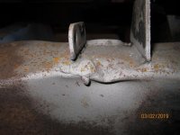
I have been an MG guy for many years, but always wanted a small mouth TR3. I bought one on Ebay planning a full frame up restoration. During tear down I noticed the right front spring wasn't straight. After removing the body it was clear the lower inner fulcrum pin was bent. After cleaning all the crud and sand blasting, the damage to the spring tower and frame could be seen. Up to this point I had considered attempting to bend the pin straight but it was clear I needed to remove the pin to repair the damage to the tower and frame.
But how? The pin is welded in 6 places, three of which are under the spring tower reinforcement plate.
 
Last edited:

jruddsr

Freshman Member
Country flag
Offline
Sorry for the strange way I am posting. I'm an old guy struggling with technology.
So how did I I remove the fulcrum pin? With major surgery! The tools I used were air die grinder with thin cut off disc, a Harbor Freight air saw, and a good quality(American made) rotary file. A good face shield is highly recommended.
Bringing yourself to make the first cut is daunting! There is no return after that cut, but it moves quickly after you have committed.

View attachment 64628View attachment 64629View attachment 64630
 
Last edited:

jruddsr

Freshman Member
Country flag
Offline
The story continues. Now the tower reinforcement has to be opened up to reach the hidden welds. I used the 1/32 cut off disc to make the cut. My cut locations were determined by the way the reinforcement was factory welded, keeping the repair welds out of the way of the engine mount, and my desire to have a big opening. once the opening was made i could reach the pin with a sharp 3/8 drill. The air saw made quick work cutting through the pin and a few well placed hammer blows with a cold chisel had most of the pin out.

View attachment 64638View attachment 64639View attachment 64640View attachment 64641View attachment 64642View attachment 64643View attachment 64644
 
Last edited:

jruddsr

Freshman Member
Country flag
Offline
The front pin is exposed sufficiently to be cut with my right angle die grinder and 1/16 disc. Now all welds could be reached with my rotary file. I used a stone grinder on the front pin successfully, but quickly switched to the rotary file. The stone cuts much too slowly and leaves a black, powdery dust on everything. When I started this project I'd hoped that carefully removing the factory welds from the fulcrum pin would result in preserving the original locating holes. That approach was successful in all but one location, but the rotary file corrected that situation. Once I filed the welds I could knock the remaining pin from the mounting holes.
View attachment 64645View attachment 64646View attachment 64647View attachment 64648View attachment 64649View attachment 64650
 

jruddsr

Freshman Member
Country flag
Offline
I will continue at a later time with how I put this mess back together. I do want to make a special note about the U-shaped bracket that holds the pin. This bracket is welded to the Spring tower and was responsible for the tearing of the metal when the pin was bent. I failed to take any photos of the process, but that bracket needs to be carefully detached from the tower and bent away to make repairs of the torn metal. Mine was welded on three sides but careful cuts with a cutoff disc released it without further damage to the tower. Leave the bracket detached until the final welding of the new pin. You will see why in the next chapter. John

View attachment 64651
 
Last edited:

jruddsr

Freshman Member
Country flag
Offline
I see that my attempt to include attachments to my posts did not work. What am I missing? Are you limited to one attachment per post? I tried to attach multiple photos. Sorry guy's. John
 

DarvinR

Senior Member
Offline
1960 TR3A starting chassis work this is my documentation to the repair I did to my frame. As stated above it is not an easy repair. I used a self leveling laser to establish the corner pads that I used to level the frame and story sticks to continually check the frame for level. The service manual is what I decided to be the road map to the information to repair the frame. The drawing of the frame gives all the dimensions necessary to completely rebuild the frame. There are also drawings of additional suspension parts that can be used to determine if they are bent. As far as tolerances, John help me decide that no dimension is off more than 1/16" that is + or - 1/32. Once the frame is level I used another laser on a tripod to establish the centerline. Gravity is your best friend to continue to check the laser. Use a plum bob hanging in front of the laser to check that it is vertically true. The laser will light up the string and it is easy to true the laser when the string is lit from top to bottom. I used a string dimension of 12 inches to true the laser. I used multiple points along the frame to establish the center line. There is a hole in a tab at the front cross bar, the frame ID tab on the cross member, measuring between the transmission mount bolt holes( put a piece of tape across the holes and you can measure and mark the centerline)unless the car has been wrecked the transmission mounting bolt holes should be very accurate. Then to the rear cross tube, same thing put a piece of tape and measure between the frame rails and make a mark. The dimensions for the body mount pads are helpful to help establish centerline. A piece of flat bar drilled for the mounting holes in the pad makes for a good reference. mark the center between the mounting holes. Use the laser and see how all the marks line up. This is where you will have to decide how many times you do this to decide on what you think is the true centerline. Centerline is a good start but you also will need to confirm that the spring towers are correct as well. I can not emphasize how important it is to continue to take measurements, check and recheck. I would say my repair was 50% measuring and 50% fabrication and welding. Good luck and take your time. Frank
That looks like a good documentation thread, thanks. We might need such guide for the TR3, we'll check it out right after we finished installing the parts from napa and 4WheelOnline on the current Wrangler JK project.
 

Tr3aguy

Jedi Knight
Country flag
Offline
When i got that it was a photo size issue, i had to choose a lower resolution photo for mine.....then it would only let me put about 3 or 4 in a post.


I will continue at a later time with how I put this mess back together. I do want to make a special note about the U-shaped bracket that holds the pin. This bracket is welded to the Spring tower and was responsible for the tearing of the metal when the pin was bent. I failed to take any photos of the process, but that bracket needs to be carefully detached from the tower and bent away to make repairs of the torn metal. Mine was welded on three sides but careful cuts with a cutoff disc released it without further damage to the tower. Leave the bracket detached until the final welding of the new pin. You will see why in the next chapter. John

View attachment 64651
 
Similar threads
Thread starter Title Forum Replies Date
J Cost for front suspension refurb right/wrong? Spridgets 8
L Wanted right front turn signal 1975 TR6 Triumph Classifieds 2
A SOLD!! TR3A Girling Type A brake caliper for right front Triumph Classifieds 0
T For Sale GT6 Mark II Right Front Fender - NOS Triumph Classifieds 0
T Wanted 1960 Jaguar MK2 front door wood trim, both right and left. Jaguar Classifieds 0
spartan0199 BT7 Right Front Brake Drag Austin Healey 30
Lin Right Front Fender Removal - 60 BT7 Austin Healey 2
M Front Right Shock Change Creates another Problem Spridgets 11
HAN8L1965 Need Right Front Fender 65 Sprite Central Ohio Spridgets 5
K TR2/3/3A Update on the head gasket repair......something is not right/ Triumph 5
J MGB Oil Pressure Gauge Gives Constant Reading -- Doesn't Seem Right MG 15
B MGB while driving engine cuts out if I let off or push more throttle it comes right back on MG 5
G Right-Side Shock Weeping Oil Austin Healey 1
C MGB Which Weber DGV is the right one. MG 14
P Jag XJ8 starts but then dies right away. Jaguar 4
Popeye General Tech O/D right angle drive choices Triumph 10
BritBite Speedometer Right Angle Drive Austin Healey 5
drooartz General MG Surprisingly enough, I was right! MG 7
C TR2/3/3A Right oil Triumph 8
5 Wanted Wanted Parts to convert BN2 from left hand drive to right hand drive Austin Healey Classifieds 0
TRclassic3 TR2/3/3A Body leans to right side Triumph 10
red57 Steering not right Austin Healey 66
B For Sale Brand New Black Tonneau Cover for BN4 and BT7 - for Right Hand Drive Car Austin Healey Classifieds 0
dougie Big Healey Six - Used the Right Way Austin Healey 5
John Turney The Panhard Rod is Supposed to be Straight, Right? Austin Healey 7
Bayless What are symptoms of steering rack not shimmed right? Spridgets 14
S Wanted Source for 100 6 right hand remote control door regulator Austin Healey Classifieds 1
C Left to right hand drive Austin Healey 2
T TR6 grinding right rear wheel Triumph 22
5 Wanted Wanted Parts to convert BN2 from left hand drive to right hand drive Austin Healey Classifieds 1
Rut TR4/4A Nice project for the right person Triumph 0
JPSmit Fuek Tank Sender - does this seem right to you? Spridgets 3
D BJ8 pulls right on hard braking? Austin Healey 4
Simmo TR6 Right Hand Drive Conversion Help Triumph 3
Jim_Gruber 13" Tires - What's out there right now Spridgets 21
Popeye TR4/4A Seats - left/right Triumph 8
TomMull Post-War Other Herald 13/60: I didn't get the battery tray quite right Triumph 4
J BJ8 Vacuum Advance - disconnected -RIGHT - when setting total advance?? Austin Healey 6
Simmo TR6 Right Hand Drive conversion Triumph 5
T TR4/4A This head gasket doesn't look right to me - cooling passanges partially blocked? Triumph 18
Zimmycobra TR4/4A Who's right - float height on ZS 175CD? Triumph 5
M TR2/3/3A Engine does not shut off right away. Why? Triumph 8
S TR2/3/3A right to the wheel well Triumph 10
T TR4/4A Making Miata seats in a TR4a look more "right" Triumph 4
Got_All_4 TR2/3/3A 2 questions; raising the body and taking out that lean to the right Triumph 12
Jim_Gruber NOS 10 Post BE Windscreen on E-Bay right now - NFI Spridgets 3
S TR4/4A water pump doesn't feel right Triumph 2
W TR2/3/3A '56 TR3 St 15000+ should have disc brakes... Right? Triumph 33
P T-Series TD Door Hinges: just what is the difference between right and left? MG 11
RickB MGB HS6 or HIF4 bolt right on in place of Stromberg? MG 6

Similar threads

Top