• Hi Guest!
    You can help ensure that British Car Forum (BCF) continues to provide a great place to engage in the British car hobby! If you find BCF a beneficial community, please consider supporting our efforts with a subscription.

    There are some perks with a member upgrade!
    **Upgrade Now**
    (PS: Subscribers don't see this gawd-aweful banner
Tips
Tips

TR2/3/3A Recipe for a TR2

Ya'll wanna know another part that is ribbing me right now? The clutch cover...part 56653. I even gave one of those away a couple months ago, since I was convinced I already had a decent one in storage. Now I can't find it, and it's NLA everywhere else. All the available covers are stainless repros that do not have the indentations of the original.

It's funny how problems tend to focus at the end of a project. For example, the steering stator tube, steering wheel, and clutch cover are examples of 3 items that were readily available over the last 4 years, but are now NLA. You reach a mindset that, "oh, they'll be there when I'm ready for them". But our suppliers are starting to dry up.

It's all manageable, I can either fix the originals or run without most of these parts until they turn up on...Gulp!...Ebay!! But it's interesting how you can never take anything in life, and especially 60 year old cars, for granted...
 
Do you find that these trips break your train of thought? After I have had a work break it seems to take a few days to get back on track.

Did the Roadster Factory ever manufacture wheels or was that a project that did not make it. Last year I had an e mail from Albert saying they were working on a source for new reproduction wheels.
My e bay wheel will get the cracks filled and maybe a wheel skin.

There seems to be several parts that there is or has never been a reproduction made. The bracket/mounting for the brake/clutch pedals for example. Mine is rusty and has previously been patched around the mounting holes but is serviceable. I would replace it if I could find a good one.

David
 
It is hard to get back into it after a break, but once I do I think I'm more productive since I've had time to think about it. I've had time to develop a better game plan. Before I left the fuel tank was really kicking my a$$. Either the boot floor is off or the Ebay tank is off a little...so getting the filler neck to align with the body opening is proving a Herculean job. But I've been pondering it during the trip, so I have at least a couple possible solutions figured out.

Also I have spent the time ordering all the little knick knack parts I will need to finish up...so I should save some time that would have been lost to shipping delays.

I'm not sure about TRF manufacturing wheels. Albert didn't sound optimistic about repros any time soon. The wheel I just bought off ebay has a couple cracks in the plastic. Those don't worry me, as I have filled them before, and once painted the wheel doesn't seem to deteriorate any more. I prefer a non-painted wheel, as they take punishment from rings and such without scratching...but I'm afraid repairs are part of the game now!?!

What scares me about the wheel I already have is that it is covered with many tiny stress cracks. With large cracks I grind them out a bit so the filler bonds well. There are so many small cracks on that wheel that it would either take weeks to grind the cracks and fill...or, if I don't fill them, I fear they will eventually crack the paint over them. I'll save that wheel for a teak project later...

In the end, all these little challenges are part of the fun of our hobby. If it was easy, everyone would be driving a 60 year old Triumph!
 
So you did not go for the $250.00 buy it now wheel. It looked great but it was high.

With parts that I really really need and the price looks sensible I will often hit the buy it now rather than risk losing it.

I get a lot of ideas worked while I am doing my evening walk.

David
 
Yeah...the $250 wheel claimed "not painted", but the pics show it was obviously painted before. I found a second one for $140, with cracks I think I can deal with.
 
I'm Back! Anybody miss me?

So...continuing on with the build....


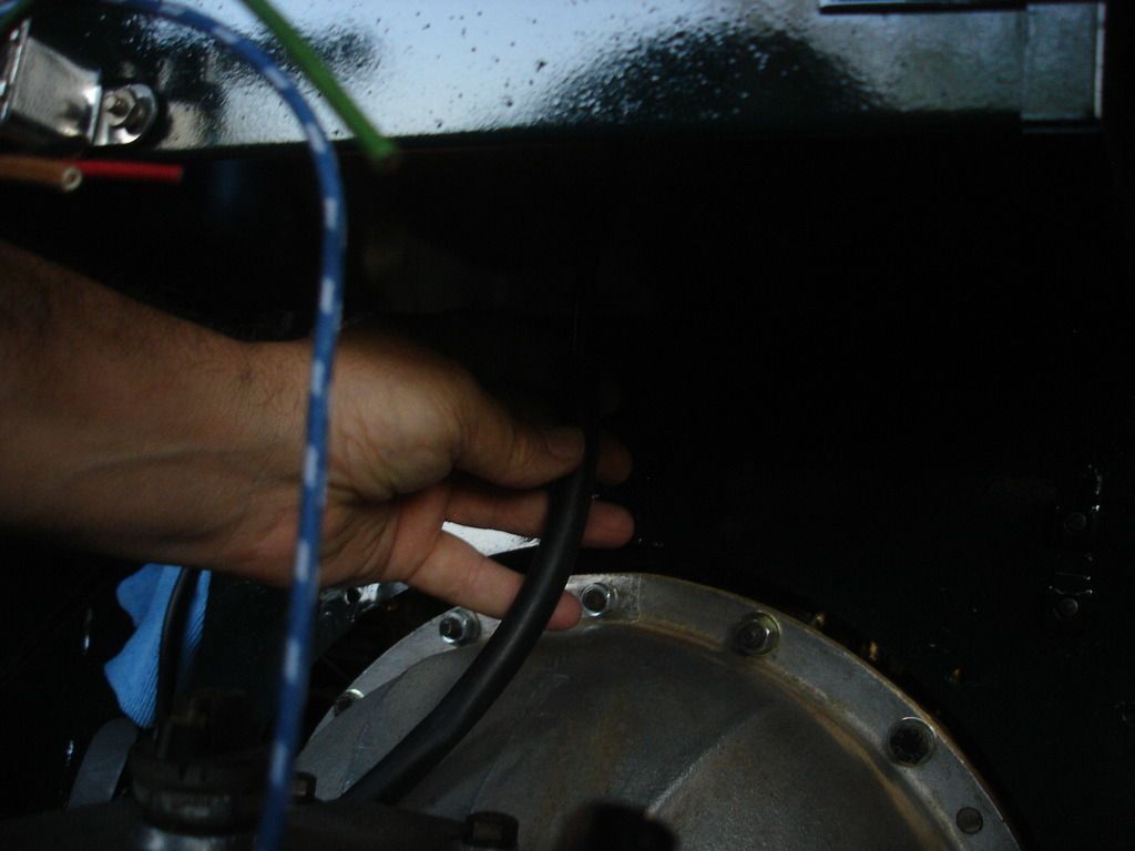
This is the battery drain hose going in place.


Battery ground cable. The judging guide says it should be round. The connector is NOT correct, but the guide also says not to deduct for this connector, since the original was finnicky at best.


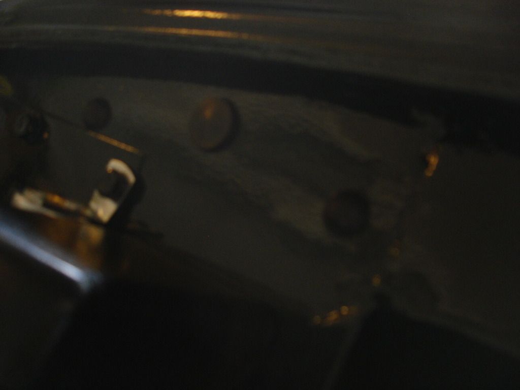
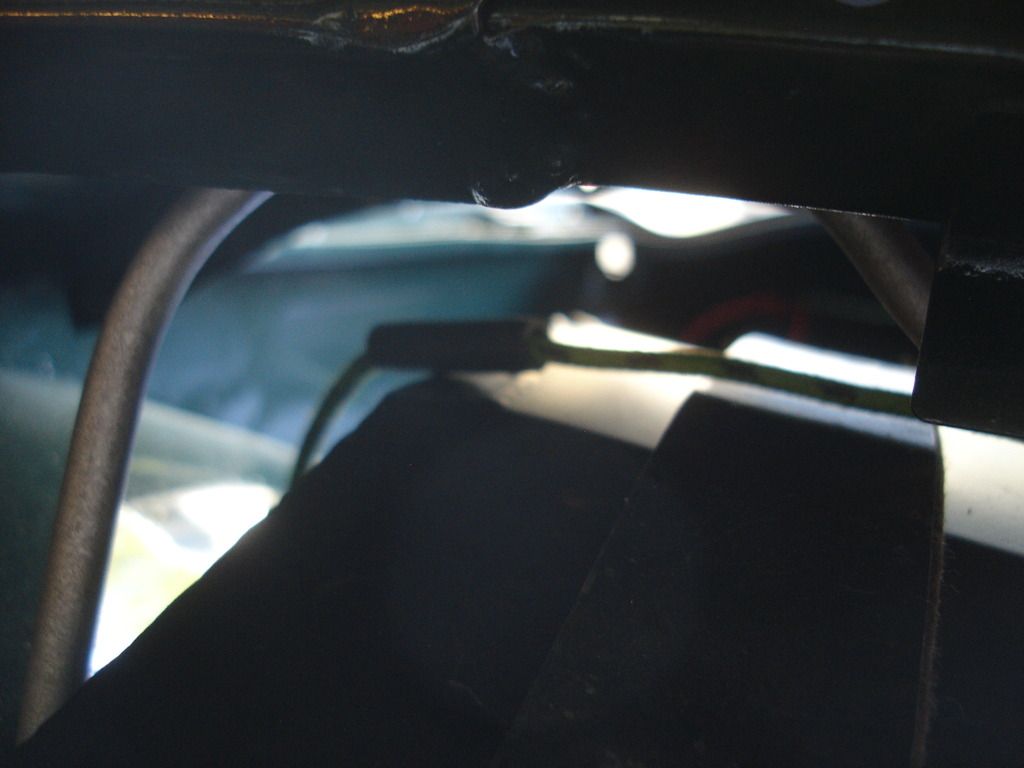
Not a good pic, but these are the 3 plugs that go over the right side brake blanking plate. On a RHD car this is where the steering column support would anchor.


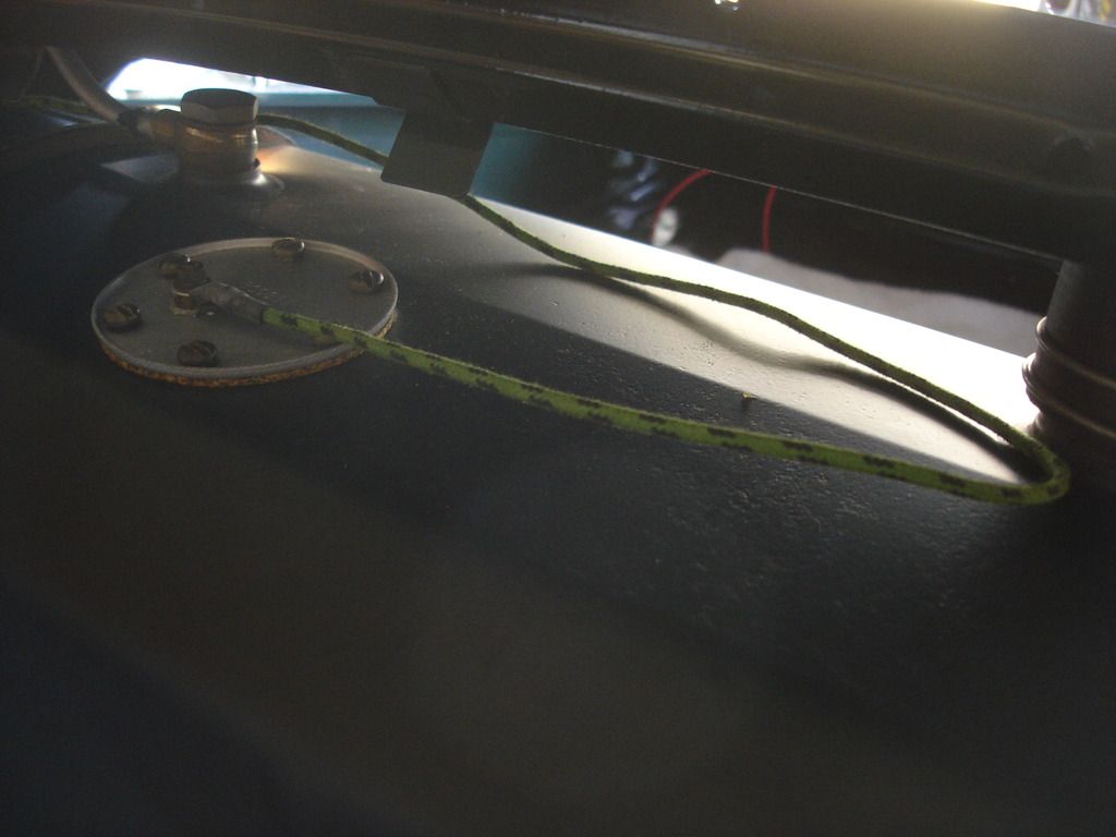
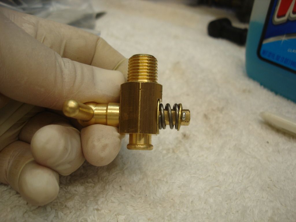
Fuel tank took 2 full days to go in. I will spare the details, but the problem is getting the filler neck to center in the body hole. Either my boot floor is different, or the Ebay tank was different. I finally fixed the problem with strategically placed felt strips under the tank. This is a pic of the tank sending wire attached.


The Moss wiring harness even has a little protector where the wire turns the corner over the top of the tank. I did have to use a tie to keep the wire so the protector is in the right place.


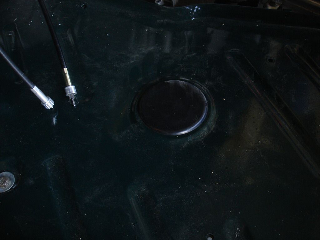
Floor plugs for the jack holes. These are not correct, but as far as I can tell, the "correct" metal plugs for the TR2 are NLA. They are easily replaced if the correct ever become available.


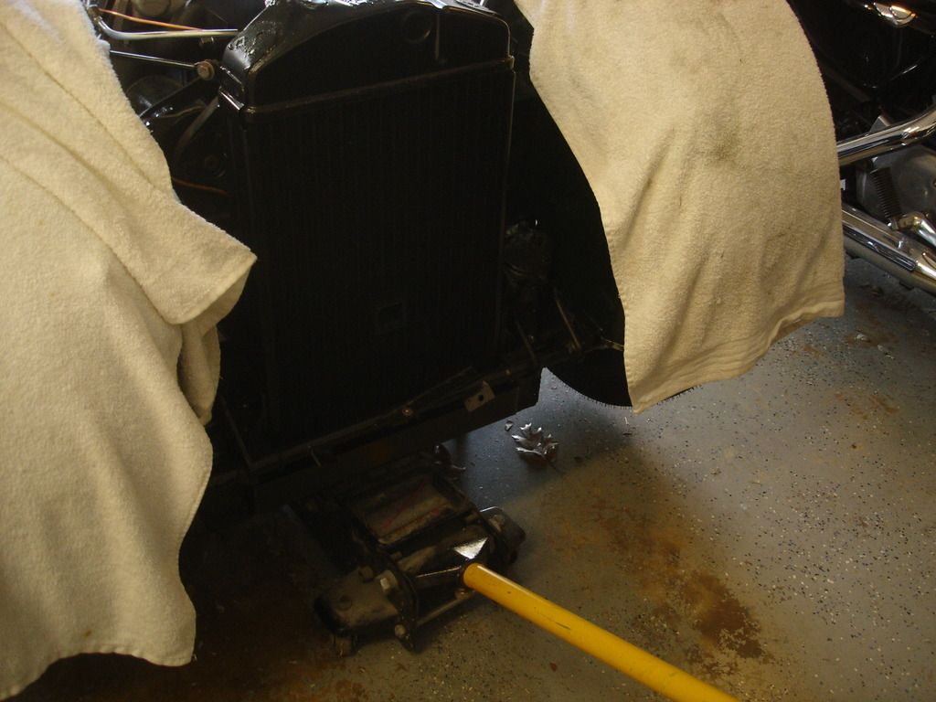
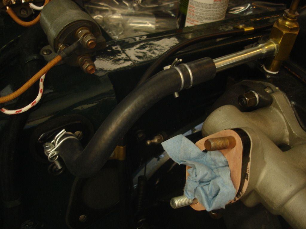
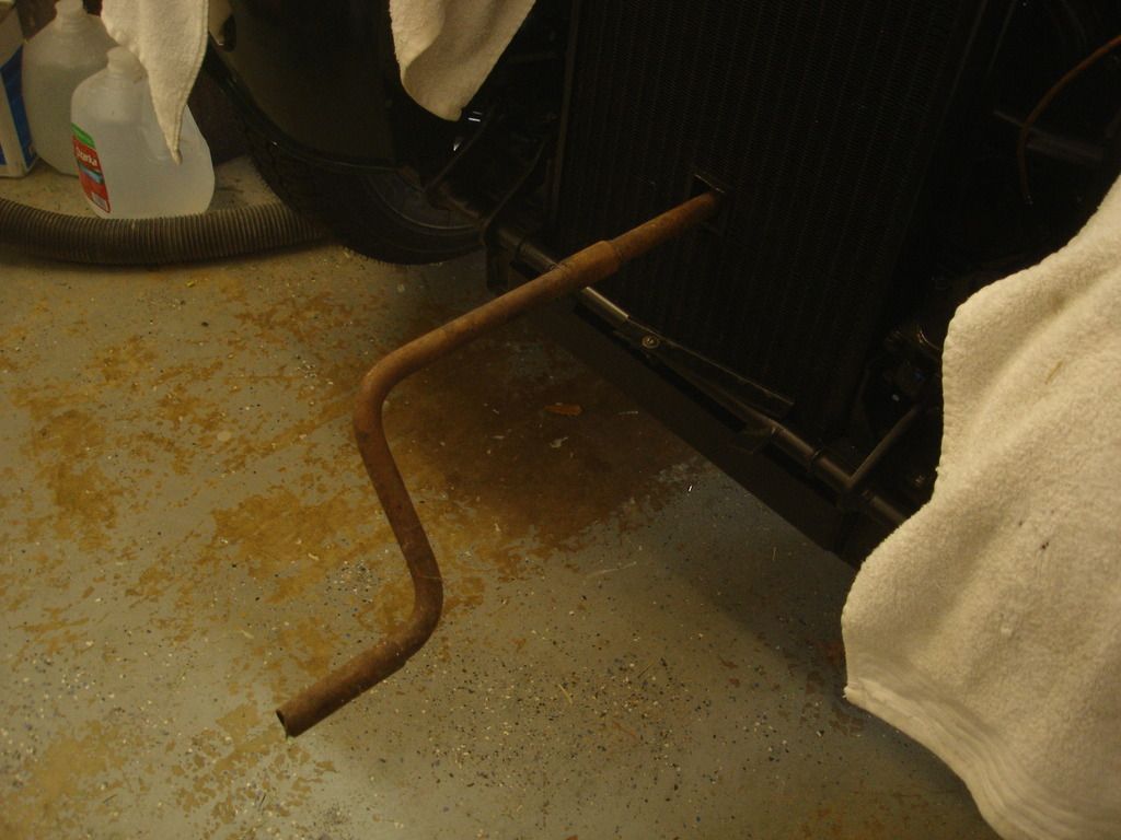
Now it's time to align the engine with the radiator. We'll start with a floor jack under the engine, using a large wood block to spread the load.


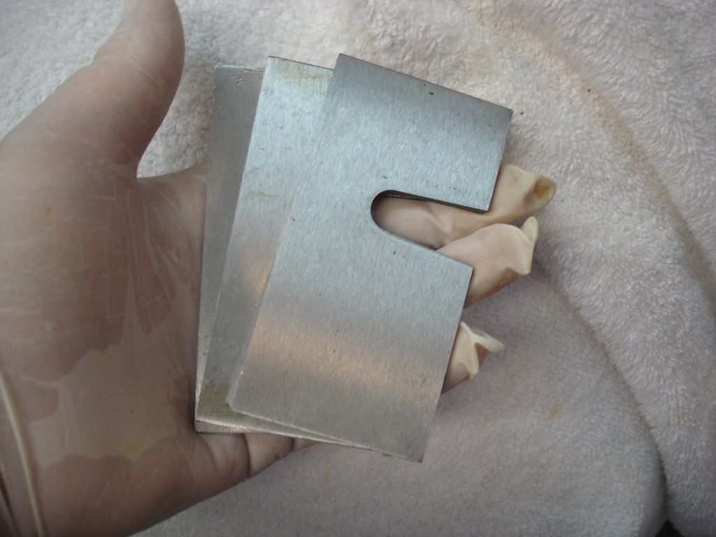
These are the shims that go between the engine front plate and the rubber mounts. (Thanks Tush!)


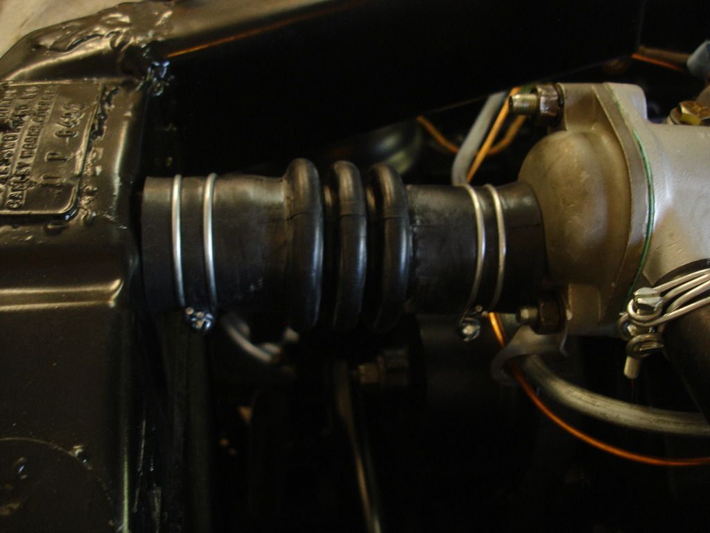
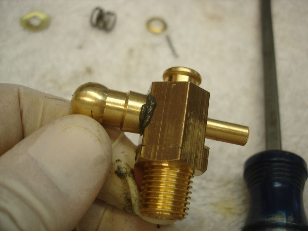
This is the original crank installed. The key is to raise the engine and install shims left, right, or both to align the crank in the radiator hole.


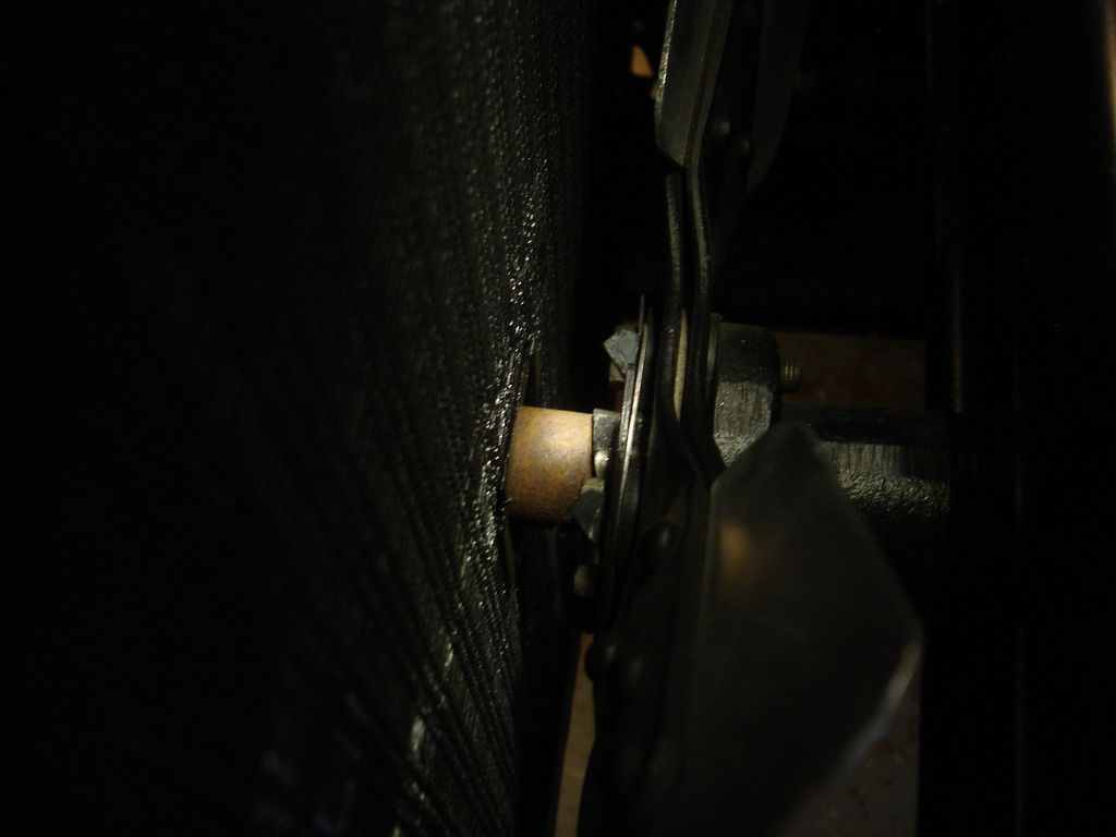
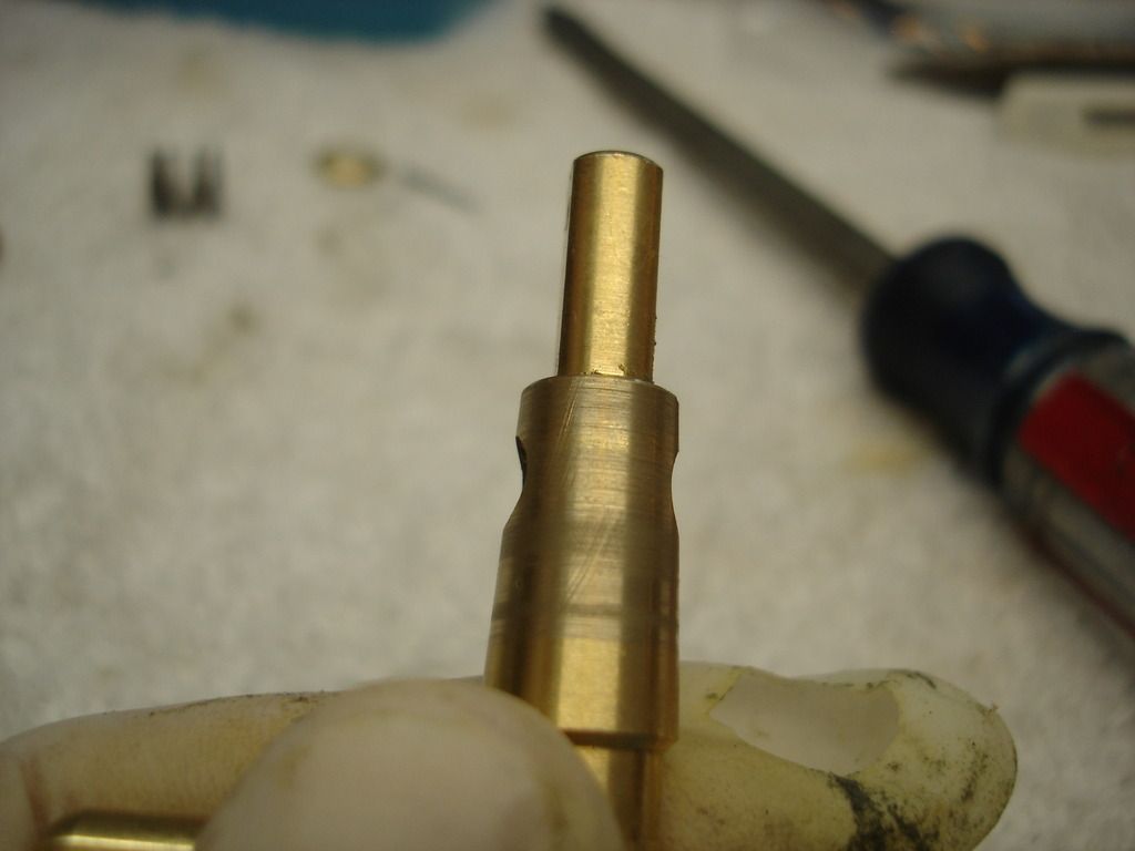
Here is a shot of the crank engaging the crank extension...dead center!


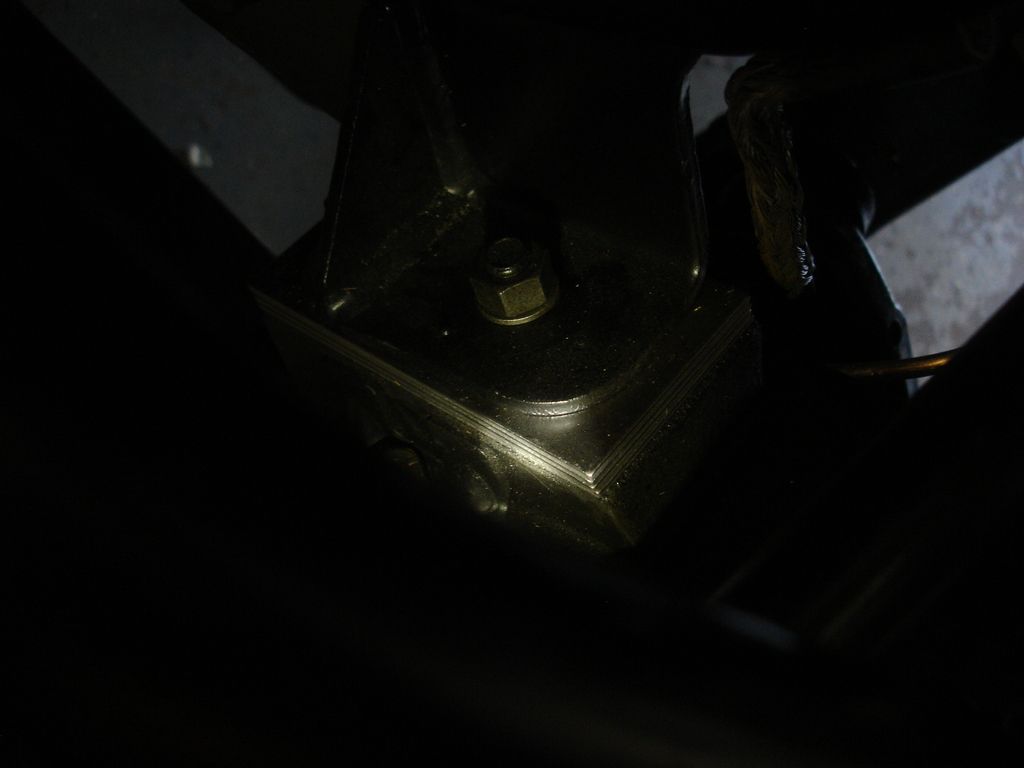
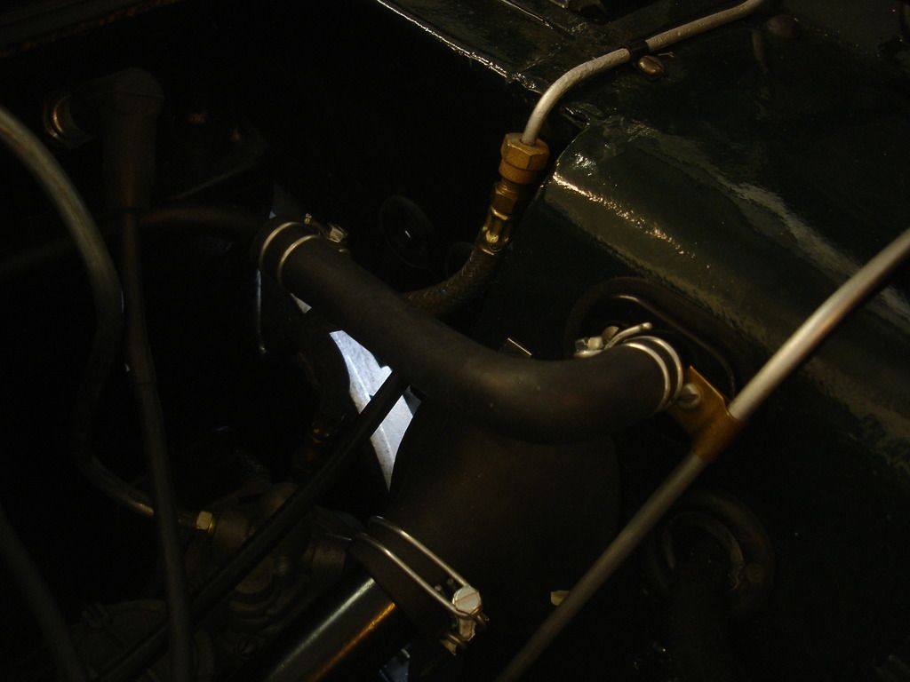
Dark, but these are a pic of the right side shim pack to do it.


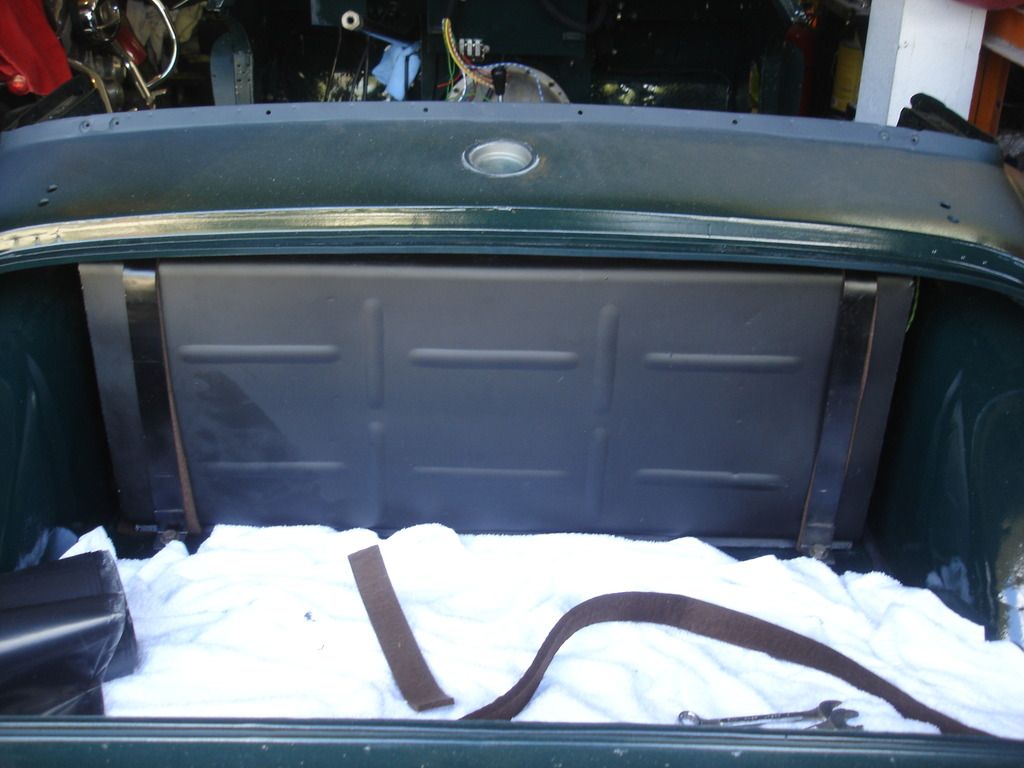
Oh...forgot to show the tank installed...


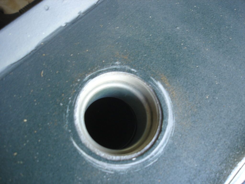
This is the PITA in the tank installation. The neck piece is a bear to install on top of the tank filler neck, AND it must absolutely center in the body opening. If not centered, it will distort your body work around the filler cap.


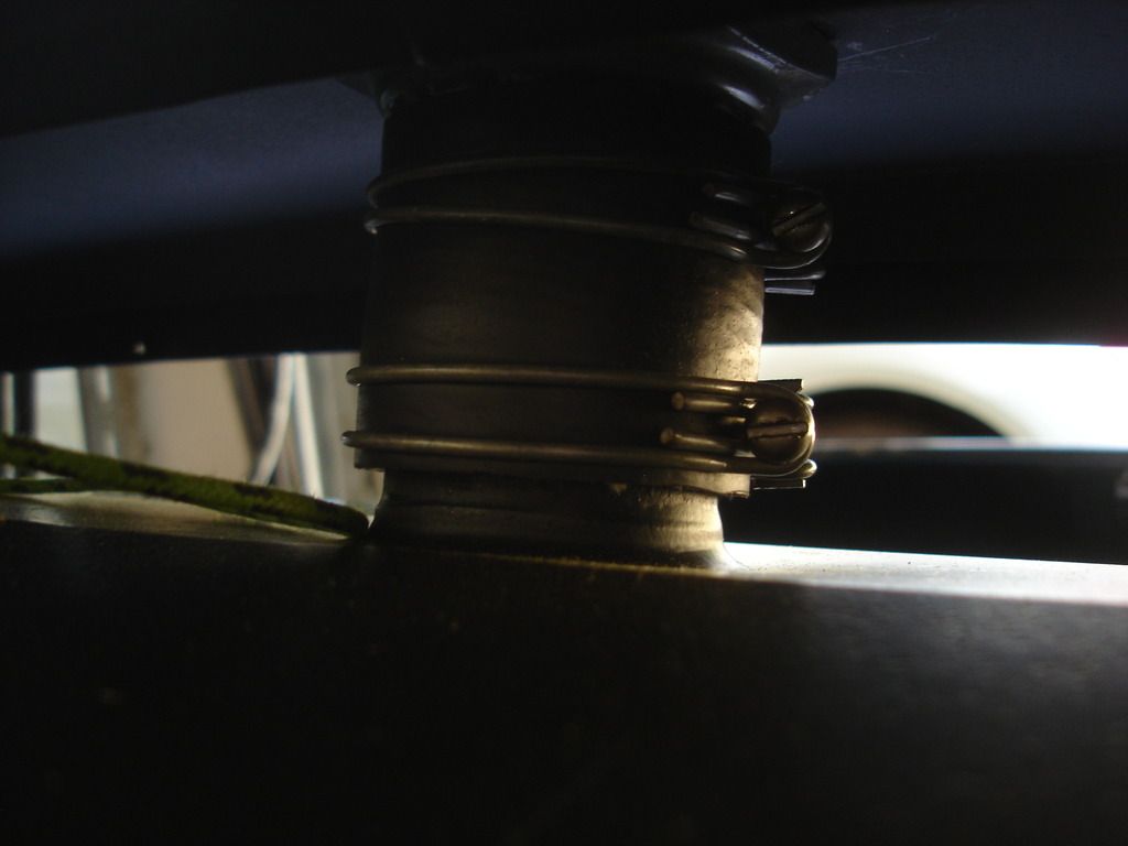
Once the extension and hose are all aligned, with the tank securely strapped down...then you can tighten the clamps to hold the extension in place.


So far the body has been loose on the frame...just in case some adjustments were required. The final adjustment is to align the rear bumperette holes. Then all the bolts got tightened from the rear to the front.


Upper radiator hose.


Lower radiator hose.


These little dookies are hose clips...used for the rear fuel line and the radiator overflow hose.


2 go on the fuel line to hold it to the boot floor. The third goes on the right inner wing to route the radiator overflow line.


Horns! The dome has to come off to wire them in.


And they're in.


This is the brace for the steering column, including all the little braces that were added mid way through the TR2 production.


Just like the 3 holes we plugged on the right, there are 3 holes on the left to mount the brace.


For now all the adjusting bolts and nuts remain loose, waiting for the dash that will align the column.

That was all day 1 back on the job. Day 2 was not nearly as productive...and no pics, sorry.

I started day 2 deciding I would top up all fluids before dropping the car on it's own feet. That included filling the brake reservoir with DOT5 silicone fluid and bleeding the brakes. Well...hmmm...think of it this way...

If you can assemble 5 60 year old brake parts and only have 1 leak out of the 5, you are doing well. I replaced over 60 parts. The leaks were everywhere!! I had to pull the copper washers on 4 fittings, sand them and re-anneal them with the torch. I had to clean up 4 flared line ends...the worst of which was on the clutch line, for which I had to reuse the original double flares...and for which the double flare nuts were bowed and would not get a good bite on the line.

6 hours later the hydraulics are plumbed, bled and dry.

Then I moved onto the steering trafficator stator tube. That was another mess! I had always planned to buy a new one from Macy's Garage, or Moss, or Rimmer. They are all currently listing as NLA. Ya'll notice a recurring theme with my final assembly??

No problem. I figured I can weld the slot back on my original stator tube, and I am sure I could...but for the wires still hopelessly jammed inside! If anyone has any ideas for removing the old wires, I am all ears. I have one end with the wires still sticking out, and the other they were chopped off even with the end of the tube by the PO. I cannot pull hard enough to get them to budge. They obviously twisted into knots after the slot for the trafficator broke off.

Uncle.

I will source a new tube from my metal supplier tomorrow.
 
I like that...tenacious!

This morning I am learning from my metal suppliers that 3/8" steel tube is not very common. The stator tube is going to be a problem...
 
Thought I read a thread a few months back where someone found some suitable tube and cut the slot. Think it came from MSC pr Granger.

David
 
David, your Grainger lead paid off. They have the 3/8" tube with the same .035" wall thickness in 304 and 316 stainless. That will work! I'll post pics with how it comes out cutting the slot.

Thanks!
 
John:
Don't toot your horn so soon after aligning the hand crank through the radiator. I went through the same process with my TS981 only to find that with the front nose installed the chromed guide was not exactly aligned with the radiator!

Lou Metelko
Auburn, Indiana
 
John:
Don't toot your horn so soon after aligning the hand crank through the radiator. I went through the same process with my TS981 only to find that with the front nose installed the chromed guide was not exactly aligned with the radiator!

Lou Metelko
Auburn, Indiana

So how did you handle that?
 
John:
Don't toot your horn so soon after aligning the hand crank through the radiator. I went through the same process with my TS981 only to find that with the front nose installed the chromed guide was not exactly aligned with the radiator!

Lou Metelko
Auburn, Indiana


Now can I toot?
 
It's about time to move back to the bodywork thread. We're down to the little clean-up items on the build.

DSC06010.jpg


The upper radiator hose installed.

DSC06011.jpg


DSC06012.jpg


Heater hoses installed.

DSC06013.jpg


DSC06014.jpg


This little dude was my next set-back. It's the drain tap valve for the radiator. There is another one on the engine block. The one shown is pretty...a repro from Rimmer Bros. The problem is it leaks. I attempted to stop the leak by lapping the valve, but it was machined too rough to lap. This makes 100% of the repro tap valves I have bought that leak hopelessly. I have better luck with the original valves. I mean, they leak too, but lapping has always fixed them. In the end I have switched to a more modern alternative valve...for now. I will find a good original tap later.

For any interested, here is how the lapping process works:

DSC06015.jpg


DSC06016.jpg


This is engine valve lapping compound found at most parts suppliers.

DSC06017.jpg


DSC06017.jpg


DSC06018.jpg


Here I am merely twisting the valve back and forth to match the body to the valve.

DSC06019.jpg


This particular valve shows why I was doomed to fail. You can readily see the machining grooves still showing. When I had lapped enough to remove the grooves completely, the valve center moved too far into the valve body. A decent valve should not have any grooves!

Bummer.
 
Back
Top