• Hi Guest!
    You can help ensure that British Car Forum (BCF) continues to provide a great place to engage in the British car hobby! If you find BCF a beneficial community, please consider supporting our efforts with a subscription.

    There are some perks with a member upgrade!
    **Upgrade Now**
    (PS: Subscribers don't see this gawd-aweful banner
Tips
Tips

TR2/3/3A Recipe for a TR2

DSC06023.jpg


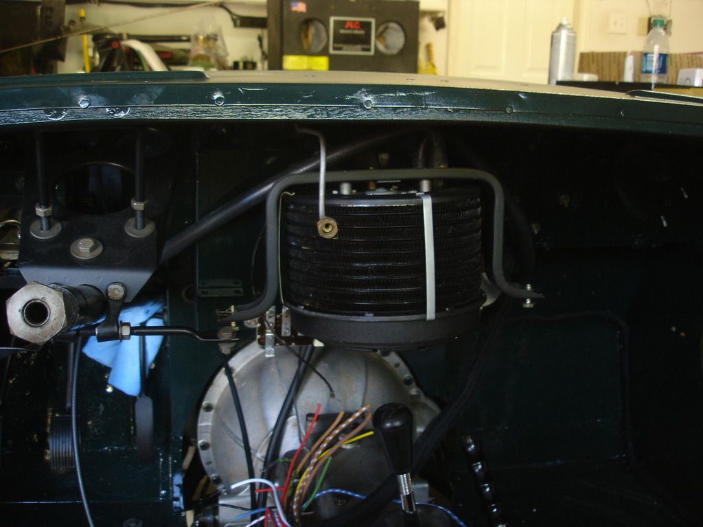
The heater is hung, although not fully secured yet.

DSC06024.jpg


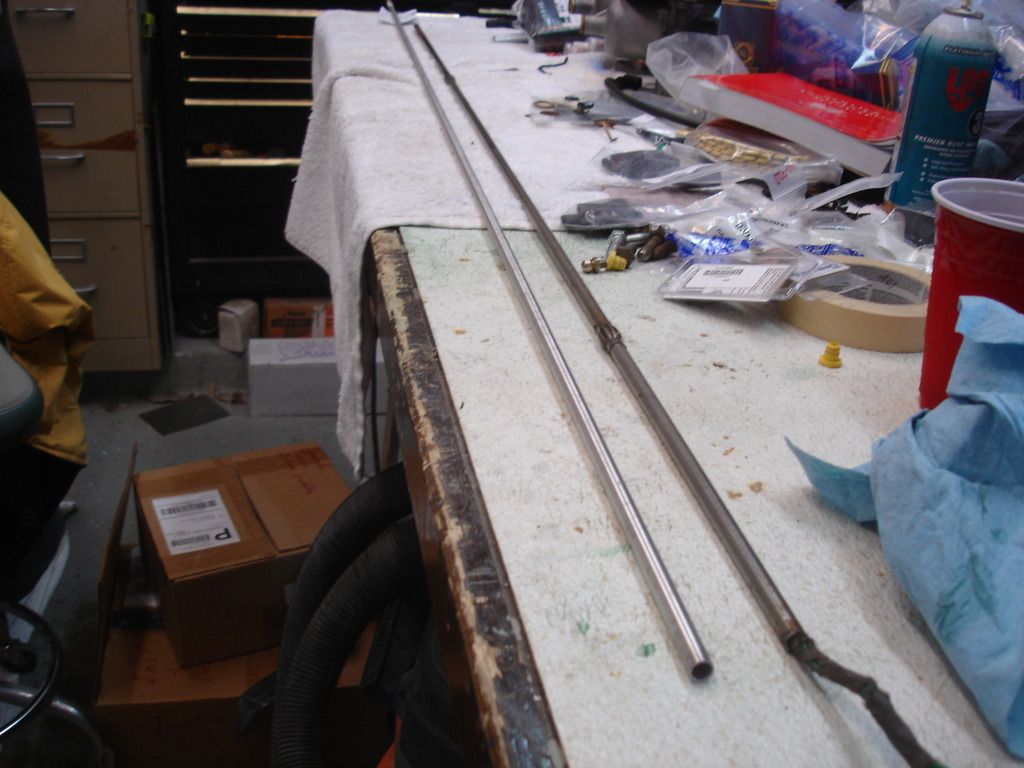
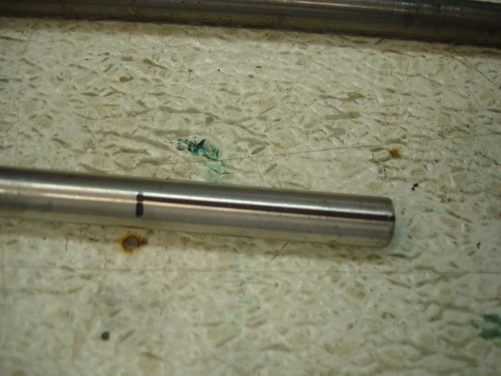
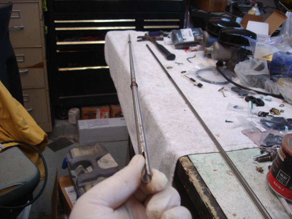
The last couple days were frought with problems. This is the original stator tube on the right. David sent me to Grainger, who carries the similar stainless 3/8", .035" walled, 61.5" long tubing. The original is not stainless, but oh well. I intended to purchase this...but they are currently NLA.

So, let's get to work building a new stator tube.

DSC06025.jpg


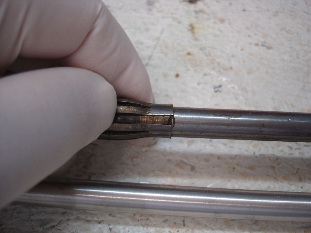
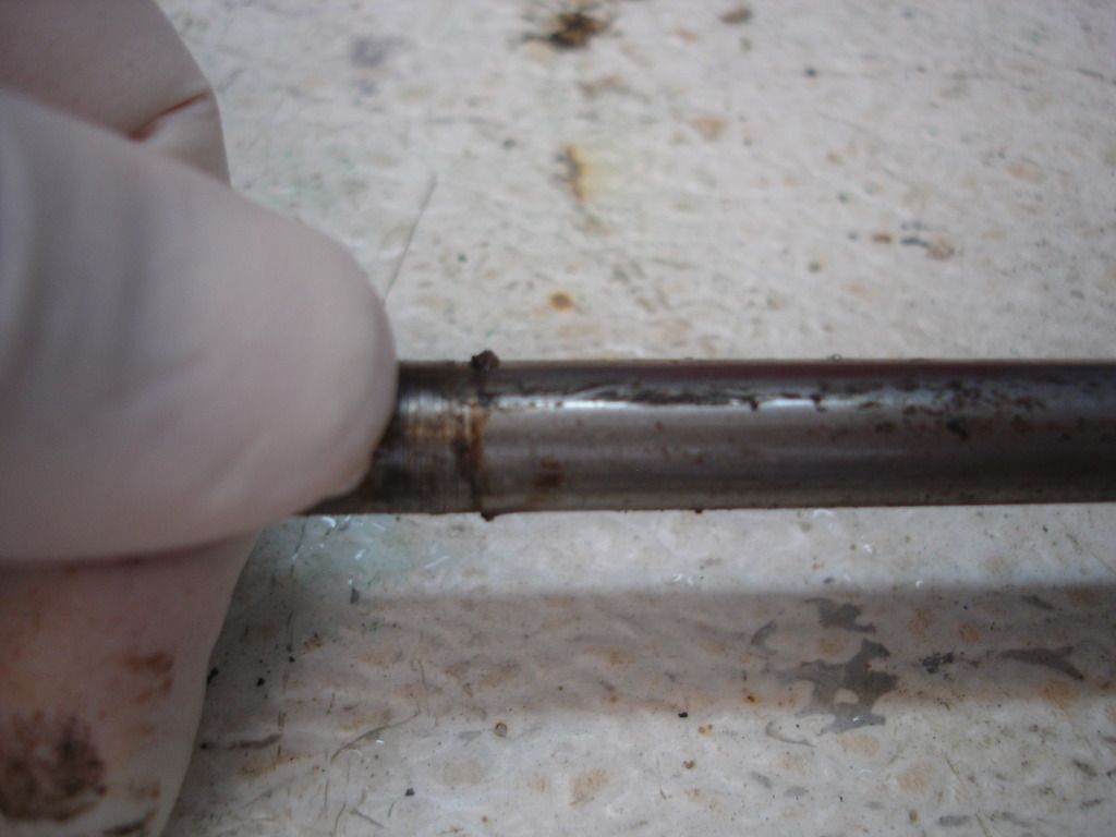
This is one of the 2 support bearing around the tube. Look closely and you see that the bearing is split, and the tube has a notch formed to retain the tube in place. By aligning the notch with the split, the bearing can be slid off.

DSC06026.jpg


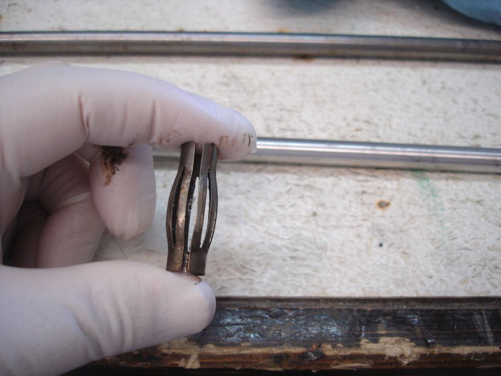
Here is the removed bearing. I learned later that the inside of the column actually has thinner ID sections to support the 2 stator bearings. The bearings lock inside the narrow areas, and then allow the stator tube to turn free of the steering shaft. I guess technically, the stator is stationary and the steering shaft revolves around it...anyway, the point is that the bearing follows the shaft, and holds the stator in place.

DSC06027.jpg


This is a blurry close=up of the notches that retain the bearings in place. They appear to have been made with a heating process, as they are heat colored.

DSC06028.jpg


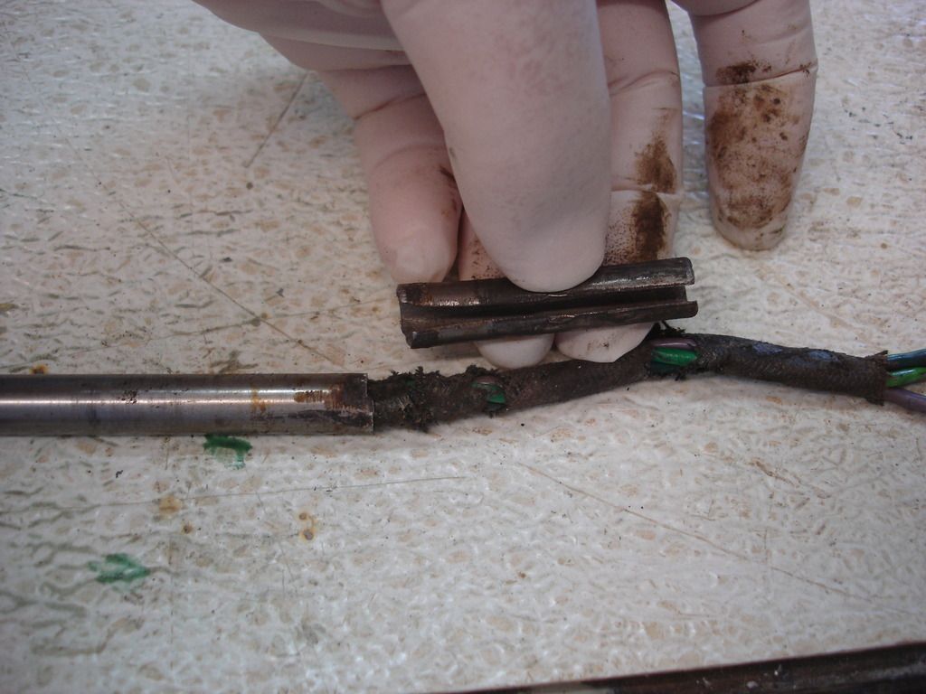
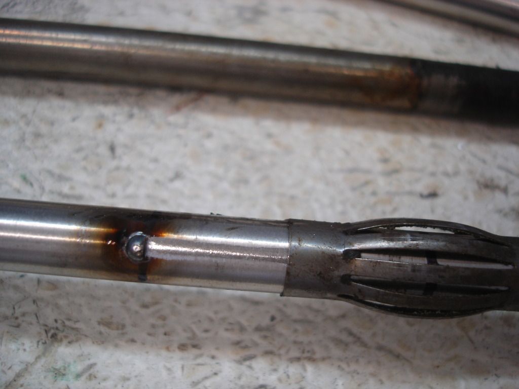
This is the main reason I need a new tube. The slotted end that retains the trafficator was broken off. If the trafficator lubrication gets old and hard...this is the typical failure mode of the assembly. The weakest link is this slot. The secondary reason I need a new tube is that the wires twisted so tightly in the old tube that they are not removable...at least by me.

DSC06029.jpg


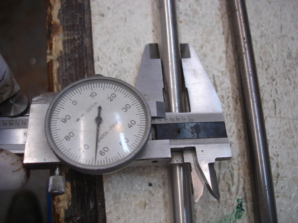
3/8" tubing should be .375". The new tube mics at .364"...exactly what the old tube mics at. So at least something is going my way!?!

DSC06030.jpg


DSC06031.jpg


DSC06032.jpg


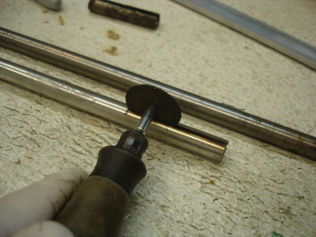
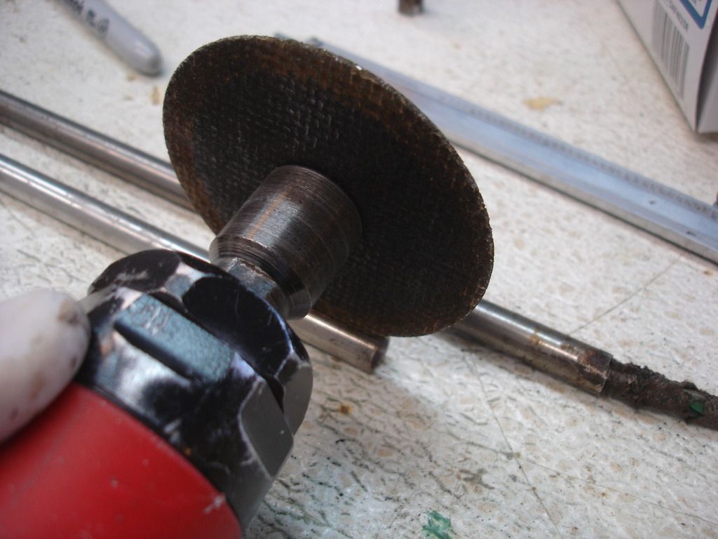
The initial cut was with a Drexel cutoff wheel. I then opened the cut with the larger cutoff disc.

DSC06033.jpg


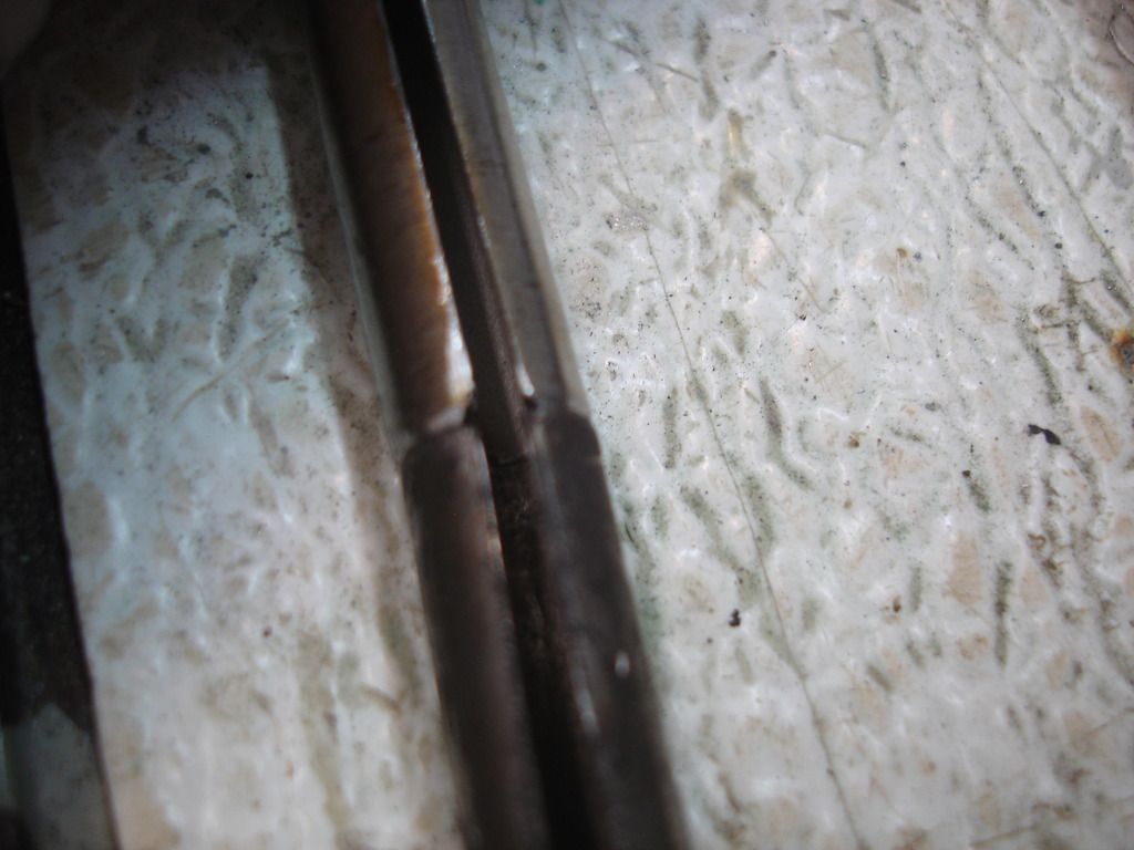
The end result of the new slot held up to the original. Close enough for government work.

DSC06034.jpg


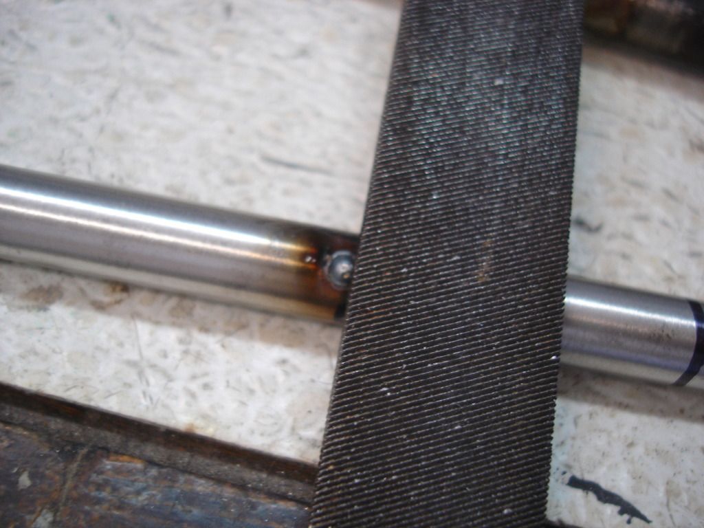
Now for the bearings. I practiced with the extra length of tubing. I wanted to leave a single tack of metal on the tube, but without heating the tube enough that the tack would go to the inside of the tube. Getting the wires through a smooth tube is hard enough. If the tack left a "bump" inside, it would ruin the job. In the pic I am filing a flat for the bearing to ride against.

DSC06035.jpg


This is the first bearing retaining spot. Once the bearing is slid into place, then I will place the second at the other end.

DSC06036.jpg


DSC06037.jpg


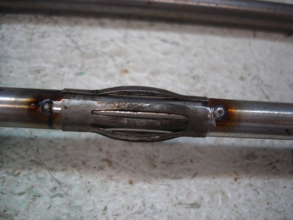
And it's done. Not quite as pretty as the original, but just as functional.

DSC06039.jpg


The end is cut to the proper length, and the new tube is ready to install.

DSC06040.jpg


DSC06041.jpg


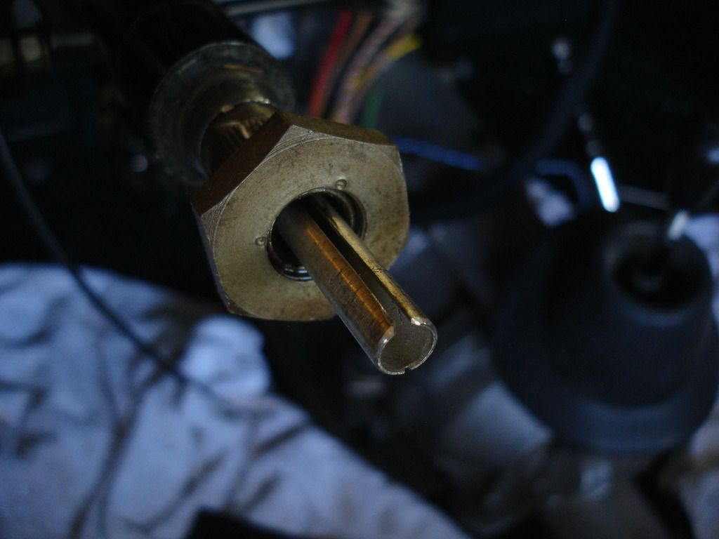
Blurry and dark...this is the steering gear end. I will have to get a new collar and nut once the trafficator is installed.

DSC06042.jpg


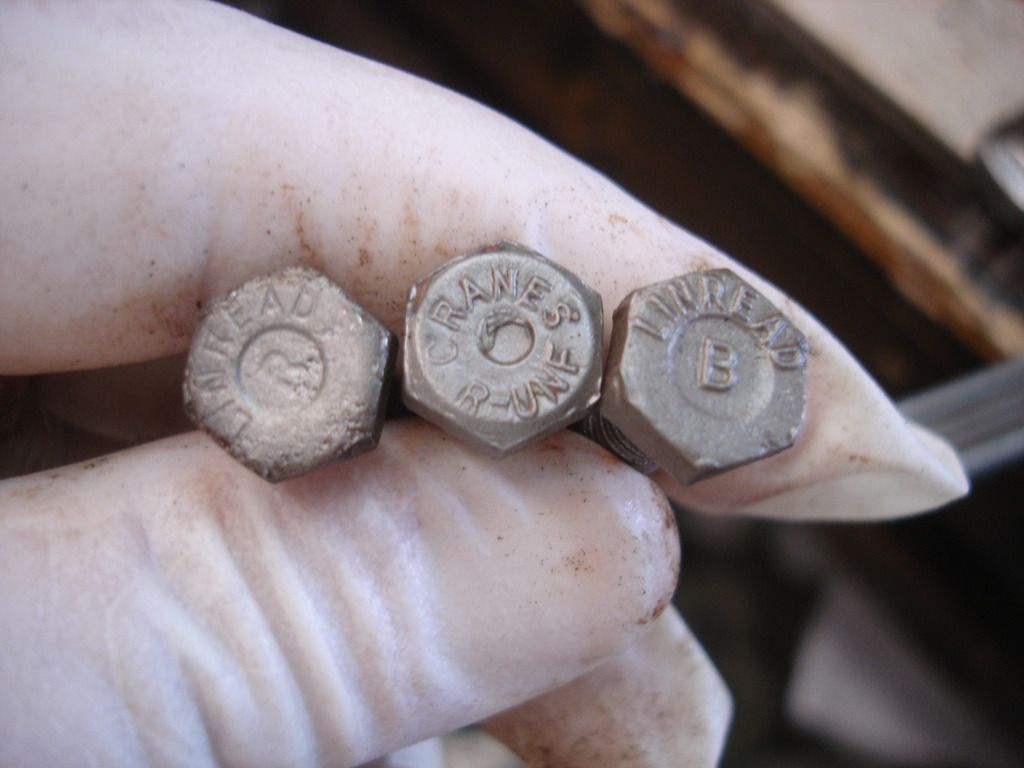
These are the 3 basic brands of bolts I have off TR3's and TR2's. The "B" was the most common on my TR2. I do not have enough of any single bolt brand to complete the entire build...So...my goal was to have the same brand in any area you are looking at. In other words, if you are looking under the bonnet, you will only see the "B" style bolts. Peal back the carpeting and you will see only "R" style bolt heads. OK...I know it's annul. Not to mention it took most of the day to bead blast every bolt, washer, and nut...AND run them through a clean-up die to repair any damaged threads.

I'm out of mechanical parts for a while...going to the bodywork thread for a bit...
 
Still up in Hawaii and reading with interest. Too bad about the tap; I've got one boxed in storage somewhere. I remember wire-brushing the bolts for my 3A so the markings would show - more for the 'cool factor'. Those in the know will appreciate it.

Jeff
 
I've been to Honolulu more times than I care to count in the last month! Always beautiful, but not so much from the inside of Tripler!?!

So...this thread is winding down, as the car is getting close to mechanically finished. After this most of my updates will be back on the TR2 bodywork thread. I'll bounce back here as the clean-up parts arrive.


I spent a couple weeks accumulating the appropriate colored, cloth covered wire for the overdrive harness. I am still waiting for the sheathing, but I managed to piece together the wiring.


Before getting to work, I installed the 2 dash braces, so I could visualize how the wire harness had to be routed.


I have learned to avoid crimped wiring at all cost. If I take the time to install a connector...I take the time to solder it. This is the type end needed for the relay connections. Granted...not exactly as the original would have been, but not too far off.


The switch ends of the wires use no connectors, but get held with set screws. Once again, for positive contact, I solder the wires where the set screw must bite them. I don't have pics, but I ran the wires where they needed to go...and then tied them together with short lengths of thread. Later, when the sheathing comes, I will just install the wires into the sheath and be done.


As the body panels begin to come back together, I thought it prudent to check the fit of the windscreen that I restored 4 years ago. Good thought, as it was a 4 hour chore.


The TR2 uses chrome brackets on the scuttle. The stanchions then slide from front to rear onto these brackets, and are finally locked in place with 2 dzeus fasteners per side.


Here was problem number one. The seal clip on the left side was so low it gouged the scuttle. Imagine the cussing if I saved this job for after the final paint?!?

Anyway, I ground the bottom edge of the clip until it cleared the scuttle by a safe margin.


Also note that I had to trim the corner of the seal. Initially the seal would roll under the stanchion as it slid backwards into place...and that forced the stanchion outward and caused a bind. After the trim, problem number 2 was solved.


Problem number three is illustrated here. All these parts were re-chromed. The problem is that the new chrome increased the size of the parts enough that they would not slide as they should. The stanchion would start to slide and then jam hopelessly on the bracket.

Uuuuhhhggg!


This took about an hour with a disc grinder, to remove enough metal so the parts would slide easily. That sounds easy, but it took planning to remove the metal where it would not show...remember the base metal is brass. Once you grind, the brass shows through. But, I got it done so it is not noticeable unless you start looking under the bracket or flip the windscreen upside down to look for it.


We've all seen this spring. It has several jobs...and each one requires Coach Fitter skill to get it working. I'm not a Coach fitter...but I managed to get it to work by the hardest. If you look at the pic, the obvious job is to pop up the bonnet so you can get a hand under it to lift it. I had to grease the spring and plunger to make that work. Job 2 is that the left side in the pic has to be positioned to engage the safety latch for the bonnet. That required some grinding. For some reason the locating holes for the cross brace were never drilled on the brace I am using. I had to remove the apron to drill the locating screw holes. "One step forward...2 steps back!"

The next job is not so obvious...


The plunger must engage a notch in the bonnet. This locates the bonnet laterally, so it will not bounce around while you drive. It's a delicate dance to locate the plunger correctly...while still getting the safety latch to engage. It all works in the end...but getting there is a another 4 hour trip!


So here is the screen after 4 hours of fitting. It now slides on easily, the dzeus fasteners line up correctly, and it slides off easily. I can install/remove it myself by standing in the car, straddling the tunnel.


Next, this is the latch for the door. It's a brand new repop from Moss. It's a decent latch...

...BUT...the spring is ridiculously stiff! You have to slam the devil out of the door to get it to latch! We'll fix that by removing coils from the latch spring.


With a little work you can open up the back end of the latch, exposing the spring.


After a trial period, I found that cutting off exactly 4.5 coils made the spring perfect. With a little work you bend the end cap back into place and the job is done. The door latch now feels like a Bentley. OK...I'm exaggerating a little bit...but it makes closing the door MUCH easier!


At this point the ... ummm ...car ...made it's first roll out into daylight, as I needed more room to install the right side door. That seems VERY strange actually calling it a car again. But it actually is a car !!

The rear deck strut had to be bent to work right. 2 things have to be adjusted. First, the rivet joint has to be at the correct angle so the strut will both stow and extend to the correct spot. Then, the little tip has to be twisted so it lines up with the prop slot it must engage.


View of the inside. I am stopped at this point, as I cannot do any more until some little parts arrive.


When adjusted properly, the latch assembly engages the striker, and the door is locked in place. My bodywork thread has more info on how to do that.


Once the boot prop rod is aligned, it's time to set up the front. First, bend the pivot bracket on the front so the rod rotates from the stowed to the extended position in the proper arc. Once that is set...then I had to heat the middle of the rod and once again twist it so the bend in the end would fit the slot in the spring assembly. So much work for such innocuous parts!


Part of the fitting procedure is to align the bonnet dzeus latches. That takes a while.


With the spring plunger properly aligning the bonnet laterally, You must look inside the dzeus holes and make sure the latch assemblies are aligned. Once that is done, you can install the fasteners and latch the bonnet for the first time. Now you must, sequentially:

Set the bumpers on each side to the proper height.

See if the dzeus fasteners are too tight or too loose to latch.

Shim the latch plates so both sides hold the bonnet securely but are not too hard to engage.


This is the last issue I am working. The boot lid seal. I have decided the design of the seal is flawed. I know this, as the design was changed...for the better post 60k. In this pic I have ground some of the side off the channel for the seal, as the deck lid got WAY too close in these areas. Hopefully this extra space will allow the seal room to flex as the lid is opened and closed. Here is the issue:

If you turn the seal outward, as most cars have it, then the nut for the hinge AND the low corner of the lid pinch the seal...eventually cutting and tearing it. If you look closely at any picture of a car with an outward facing lip, it will have cuts in the area of the hinge nuts.

THEN, if you decide to turn the seal lip inward, the seal clears the hinge nuts and lid, but now it catches the latch assemblies at the bottom of the lid.

There is no solution. I adjusted the height of the channel, but will await more thought time...and beer...before making a decision to install the seal.


I'll finish out the week with these pics of the engine bay. The carbs are waiting for the starter wiring. No sense fitting the upper parts until the lower ones are done. So...until the next parts box arrives....!
 
I just got my head back in the game after a little a business/pleasure trip, and now she has got me going to LA and Phoenix on 2nd of April for 3 weeks to see family. I am just now getting into your frame thread John and I enjoy watching your methodology. I get new idea and see that I have learn some things similar, but again your experience is really shows. Keep up the nice work.


I moved my tub to the frame I am using and now having door trouble, so I will humbly post for your input when I get bakc. Plus our weather is getting warmer and perhaps I can fix some of my other learning experiences.
steve
 
Looking great John....you will be motoring in no time!

Cheers
Tush
 
I've been to Honolulu more times than I care to count in the last month! Always beautiful, but not so much from the inside of Tripler!?!

My question is a little off-topic, but what is a "tripler"? My curiosity is getting the better of me!

On topic - thank you for putting all this information out here. I hope to follow your lead sometime in the next 12 months, albeit on a 4A.
 
Tripler is the Army medical facility in Honolulu. My daughter, in the Coast Guard, came down with Bipolar disorder. Her first episode was an anomaly, the second was a diagnosis, and 3rd was a quick discharge. We're finally getting her back to a treatment facility here in Texas, but I had to make 3 trips to the Islands to unwind her episodes. I may have to go again to help with some federal court problems...seems they didn't like her 4 wheeling over the volcano in the national park on Hilo.

But...that's just family stuff, and part of life!
 
Thanks guys. She's in treatment for 30 days, so I can sleep well. Once she's back out the rollercoaster starts again!

Anyway...


I got the wires and loom material in for the overdrive harness. This is the end that goes through the tunnel and to the tranny. I'm pretty proud of myself in being able to track down all the correctly colored cloth wire. It only took 6 weeks!?!


Now this is the main overdrive harness. It likely does not look like the original, but it has all the correct wires going to all the correct places...and the outer cloth loom to hold it all. I'm calling it close enough.


Here is the bottom of the relay I bought off Ebay several years ago. When I went to wire it, the TR2 diagram calls for C1 and C2 posts. As you can see...this relay has only C2 and C3. I got scared, as even Randall agreed that this was likely a "normally closed" relay. In other words, the overdrive would be on all the time until it was supposed to be, and then it would trip off!! Not really a good idea.

Since the "correct" relays are completely NLA (again, should I start to get paranoid about all these fading part supplies??), I decided I would crack open the case to see if there was a way to modify this relay to "normally open" configuration. Here's what I found...


Now, for those not electrically minded...I caught a real break here!!! The contact you are looking at is open, and that's what I need for the overdrive! Whoo Hooo!

I get so used to setbacks that it is really nice when something works out right. I have no idea WHY the connectors are listed as C2 and C3. They are in fact mislabeled and this should be a C1 and C2 type relay.

For others who follow, the correct relay IS available if you want to switch to lucar connectors. The screw connectors for the TR2 is long gone, so if you need/want one, start trolling for NOS now, as it will take a while for one to turn up.


So here we all, all back together and re-installed iwth the correctly colored wires and all.


And for those following this thread...it's just about to wind down for good. I have a handful of originality corrections to make...and a couple more wires to install when the cloth covering for them arrives...but then the car is mechanically finished. I cannot do the dash wiring until Mr. Skinner supplies the interior material to cover the dash before inserting the gages and switches. So...it was fun while it lasted...!


Here is the cloth cover I ordered for the battery lead going to the starter.


And the caps for each end. Yep, this thread is definitely slowing down!
 
Wow...a true tragedy. I have noticed that there is no logic to a bipolar mind. During an episode they think their actions are rational, but rational to an imaginary reality. Asking "what was she thinking" has no answer. With the meds, all her thoughts become rational to the "real world" again. She's in treatment for another 3 weeks, so I can rest easy...for now.
 
John,

I too have a daughter who is Bipolar. Please feel free to PM me if you ever want to.

I appreciate your postings, especially the photos.

Thanks,

mgf
 
Thanks MG. I'm sure things will stir up when she gets out in a couple weeks!?!


So, here are the 3 steering wheels I have. They are an interesting lot. I got one from Marv...no chunks missing, but a good bit of spider web cracking in the plastic rim. One from Ebay looks good except for 2 areas that shrunk and then opened up into 3/16" gaps in the plastic. And one Ebay that turned out to be a faux wood wheel. Interesting, but I assume a repro??


If you eye-ball the center to the wheel rim, you will notice the mis-alignment between the two. Every one of the wheels has mis-alignment.


This is a modified chisel. I ground it smooth on the edge to use in bodywork, but it seems to come in handy for many other things that involve hitting things without marking them. I will use it now to straighten these wheels.


This reminds me a lot of straightening steel crankshafts. Notice the rim and center are set solidly against the work table, with a towel to prevent marring them too badly. Then I will rap the chisel, using a paper towel to prevent marring the spokes when I hit them. With a little back and forth work, we can get the rims aligned to the center hub.


Once aligned, we need to take care of the splits and cracks. This borders on bodywork...but since we brought up wheels in this thread earlier, I'll continue here.


As with fiberglass cracks in bodywork, never just fill a crack and expect it to not show up again. You need to open up the cracks, and make good, rough surfaces for the filler to bond to. Here I am using a dremel cut-off disc to open up all the cracks...no matter how small.


Uglier than when we started...but this has left a rough surface AND more surface area for the filler to bond to.


Here I am following all the little spider web cracks around wherever they go.


Now the entire rim gets a good sanding with 220 grit paper. This is, again, to provide a nice rough surface for following steps to adhere to.


Now we need filler. I am using polyester...which is OK. Even better would be an epoxy glue with some sort of filler added to it. Epoxy bonds better than polyester.


Just like bodywork...everything gets filled!


The wheel will get primed before being painted, so I will use 100 grit to speed the process. 100 grit will not show through the primer layer.


Even here...block sand whenever possible.


After the sanding, here is what we have. No more cracks, mars or gouges!


I am restoring the 2 best wheels. The 3rd is going back to the shed and will later be a project to install a teak wheel on it. That will be much later!

Anyway, here I have taped off the spokes, so the wheels are ready to prime.


And here they are all primed.

Form here they will get spot treated where needed, and then sanded with 400 grit...painted black and clear coated for durability.


I am VERY excited about having found this in my shed!! It has not been available for decades. But, with this rusted hulk as a pattern, I can duplicate replacements to look just like the originals. I'm stoked about it!

But...I won't spoil the surprise...does anyone recognize what it is??
 
Bingo...!...you win the TR2! Oh, wait, not that much!?! Just the distinction of being a Triumph nerd. The bridge looks like it is just rivetted on, and serves as both a handle and a locking clip. I was going to go with the newer, and only available, rubber plugs, but now I have a pattern to fashion original plugs. I know I need to get a life when THAT excites me...
 
Back
Top