• Hi Guest!
    You can help ensure that British Car Forum (BCF) continues to provide a great place to engage in the British car hobby! If you find BCF a beneficial community, please consider supporting our efforts with a subscription.

    There are some perks with a member upgrade!
    **Upgrade Now**
    (PS: Subscribers don't see this gawd-aweful banner
Tips
Tips

TR2/3/3A Rear tail light cutouts

Thanks for the photos David. They will help when I start on the fabrication. Have slotted them away with the other snippets of information.
Just made pedal controls for my bead roller today. My neighbour gave me a washing machine which provided a biderectional motor and planetary gearbox to power the roller via a number of old pulleys and sprockets from my old motor bikes. Now I am hands free with forwards and reverse. Can do flanges etc without my wife cranking the handle.
 
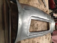
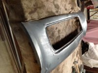
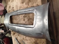
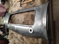
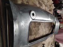
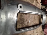
So much for my big talk. Was able to do the flanges on the short sides but found handling the panel and foot pedals and keeping on line didn't work for me. Back to the crank handle and my wife turning it while I controlled the panel. Flanges done and now chasing in the opening for the spare wheel. Lots of tidy up to do though. Not easy to chase the channel without affecting the overall curvature of the panel.


IMG_1187.jpg

IMG_1189.jpg
 

Attachments

  • IMG_1186.jpg
    IMG_1186.jpg
    66.5 KB · Views: 96
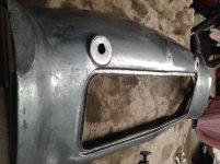
Finally got to play around with the plinths for the indicator lights. If you look closely you will see a small slit in the top flat section where I got a bit over zealous working the metal up. Doesn't pay to hurry the metal. Nothing that the tig won't fix. Called it quits after that although I would have liked to raised them a little further. Most of the work was done with a small blocking hammer on the sandbag and then the sharper edge defined with an old cup head bolt shaped on the bench grinder. I have a range of bolts I have shaped now for doing tight relief corners. Pardon my terminology as I'm not sure of the correct terms.

IMG_1192.jpg
Likewise, although the channel is not finished yet, most of the shape has been done first on the sandbag and then the lip turned up over a piece of 3/8" steel plate held in the bench vice. Again the channel on the corners was worked with another old bolt shaped to fit in the bend.

Doing the channel has flattened the curvature of the overall panel and so I am going to make a roller to allow for the curve to be worked back into the panel, a bit like wheeling the panel but only along the channel. Hope it will take some of the tooling marks out of the channel as well. Had to have a go at making the channel just to see if I could do it. I know some people will make the channel separately and then tig it into a cutout in the panel. This was going to be my fallback plan if I messed up the channel.
 

Attachments

  • IMG_1190.jpg
    IMG_1190.jpg
    63.4 KB · Views: 100
  • IMG_1191.jpg
    IMG_1191.jpg
    59.9 KB · Views: 102
Very nice! The little bobble on the top of the plinth is seen in many of the factory panels too. They used lead to cover it, but I bet you'll do better.
 
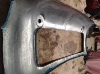
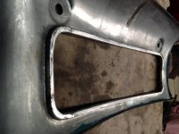
I decided on a tactical retreat with respect to the channel around the spare wheel enclosure. Having chased the channel in, I realised that stretching the side walls of the channel had flattened the profile of the panel and the only way to get the shape back into the panel without damaging the panel would require shrinking the back of the channel. Too hard for me to do with my limited facilities and skills. I cut the base and the lip off the channel so I was left with a flange on the panel around the opening. This allowed me to shrink the flange and bring the curvature back into the panel. I have been using the door of the enclosure as my guide for the curvature as it fits neatly in the existing car panel.

IMG_1197.jpg
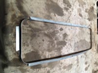
I then made a new back and lip for the channel. This allowed me to curve it to match the panel by stretching the lip. It was also nice and straight with minimal tool markings, unlike the previous channel
IMG_1195.jpg
This was then tigged into the opening which left the welds on the inside. I used several pieces of half inch tool steel to set the width of the channel when I clamped it in place for welding. The back of the welds will be covered by the spare wheel carrier and any weld through will be behind the rubber seal for the door of the enclosure.
IMG_1199.jpg
Welded the corners in separately rather than create the corners by stretching the outer edge. Too much hassel with thinning of the corners with stretching.
IMG_1202.jpg
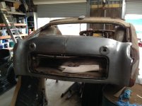
Flight of fancy to see what it will look like on the car eventually. We refer to this car as my thirty year project. Will no longer have a drivers lacense by then. Got to start thinking about what I work on next.
IMG_1203.jpg
 
Hello Lionel

Making good progress. It can be hard to have to cut out parts of your new panel but sometimes it is the only way to go.

David
 
Amazing work! You are tackling, by far, the most difficult panel on the car. Everything else will be easy in comparison.
 
Not so sure on that. I pulled down the right rear fender from my wall where all the to-do parts hang and realised how terrible it is. Metal is as thin as can be from corrosion both inside and out. Will have to seriously start looking for some more substantial replacements that I can at least refurbish. I don't feel up to making two from scratch. Have just rejoined the register here in Australia and will have to put out a request. My lack of budget definitely doesn't stretch to new panels. In fact I'm currently looking at making a punch to cut cage nut blanks to save money!!!
 
Home made cage nuts may be better than the ones you get from the big 3. I have had to work on all the ones I have used to get the square nut to stay in the pocket and not fall out.


David
 
Home made cage nuts may be better than the ones you get from the big 3. I have had to work on all the ones I have used to get the square nut to stay in the pocket and not fall out.


David

Or you can get better weld nuts from Mcmaster-Carr, or Macy's Garage. I used the ones from McMaster (Macy's sells the same ones). They are much better that original as the nut is positively attached but still has room to align. You can weld or use pop rivets. There are the few weld nuts on the TR that have the elongated holes in which you might have to use the originals if you feel that you will need the extra alignment.

https://www.mcmaster.com/90955a113


https://www.macysgarage.com/myweb6/Parts/tr2_3_hdwe.htm

 
David, Art. I am going to need about 100 cage nuts since I have fabricated new inner rear fenders, firewall, rear floor panel, rear side panels and will be replacing the outer edge of both inner front fenders. Where they are available, I will re-use the nuts but many have the bolts broken off in them.

Art, I like the cage nuts from Mcmasters and Macys. They are a quality product. A shame things have happened that now make it unviable for Macys to supply internationally.

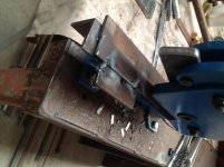
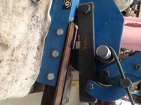
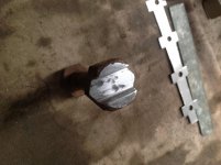
As an exercise I thought I would have a go at making the cages. I have a cheap HF type bench shears and thought I might be able to adapt it to punch the sheet metal. To cut the whole cage would take to much force so I opted to punch the edges out of a strip. I used an old file to make the cutting die and the female form it punches through. The die was set into a blade I copied from the original blade in the shears. The die and the form were fabricated with an angle grinder and bench grinder. I clamped the cutter between several heavy pieces of metal as heat sinks while I tigged it into the shear so the strength of the cutting edge would not be harmed. The shear is simply a length of 3/8" flat bar. The female form is welded to a length of angle bar which bolts to the frame of the shears. There is a fixed fence to set the depth of cut in from the edge of the strip of sheetmetal. The blade has a detent at the back which sets the position of the cut so I can feed the sheetmetel in and the next cut is set up ready.
Sorry but still can't make sense of which way a photo taken on my iPad will upload.
IMG_1215.jpg


IMG_1216.jpg

The head of a punch for shaping the cages over the pedestal. A perfect example of the angle grinder as a precision milling machine. (It does the job! Happy to accept donations of a milling machine for my next project)
IMG_1214.jpg

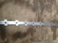
Resulting strip after punching and drilling the bolt hole. Initially I anticipated making a punch to press the holes but found marking, centre punching and drilling the holes didn't take much time. Since the bench shears are currently re-employed, I separated the cage blanks with hand shears.
IMG_1210.jpg

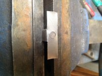
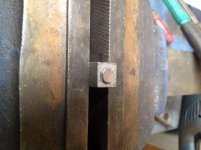
Half inch square pedestal to shape the cage over.
IMG_1217.jpg

First bend with punch
IMG_1219.jpg
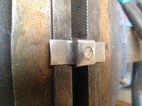
Second bend with the punch.

IMG_1220.jpg

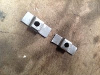
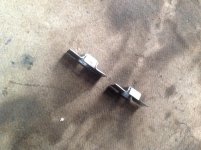
First two attempts. First one a bit rough as I sorted out the depth necessary to puch the sheet down.
IMG_1221.jpg

IMG_1222.jpg
No problem with the nut falling out. 10 done, 90 to go!
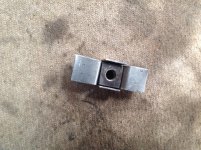
IMG_1223.jpg

Next job is to set up how I am going to make a mass of nuts to go with the cages. My lathe has been put on notice!
Lionel
 
Hello Lionel

Impressive work with such limited equipment. The cages look every bit as good as the big 3 cages.

The nuts may be easier to do on the drill press. I worked with a guy that had to produce a lot of special nuts. He would create the nut blank with a hole then had a machine tap with a long parallel shank so he could just put the nut blank in a fixture to stop it turning then tap through the nut leaving it on the shank and tap the next nut. Would have 10 or 15 nuts rattling around on the shank before he took the tap out of the drill press and dumped them off the shank. You need good tapping fluid to do that.

David
 
Lionel, I have heard about guys like you sent to earth to teach. I was out back looking through my junk pile for an old gas tank I had, but I must have thrown it out. My thinking was I could fix it or cut the nipples and opening out of it to someday maybe make a tank because they getting so expensive and the re-pops are crap looking, but then I thought no, who could do that?. You are very talented.
Keep posting please-- I will not turn you in for not being human --Steve
 
Hi David.
they lack the details such as rounded corners but given they are hidden away in the main I'm not getting upset.
Now the tools are sorted, the rest of them will be pretty easy and hopefully reasonably consistent.
I was hoping to use a reduction drive tap holder in the lathe. As you suggest it could just as well be done in a pedestal drill.
As with the other bits I have been making, apart from saving money, the fun is in seeing if I can do it.
 
Awseome work! When you’re done you’ll have enough dies to start building brand new Triumphs!
 
37 and counting. Now doing them in a strip of 15 complete with rounded corners per original. Marked out 45 so have a backlog to complete. Now the tooling and methodology are sorted they can be fabricated quite quickly. Might have got more done today but the sun was shining and I took my old motorcycle for a blast for a few hours. There's always tomorrow!
 
Back
Top