• Hey there Guest!
    If you enjoy BCF and find our forum a useful resource, if you appreciate not having ads pop up all over the place and you want to ensure we can stay online - Please consider supporting with an "optional" low-cost annual subscription.
    **Upgrade Now**
    (PS: Subscribers don't see this UGLY banner)
Tips
Tips

new wiring loom

toxig

Freshman Member
Offline
I am restoring a BJ7 and I am in the process of fitting a new wiring loom and electrical components before fitting the engine.
I am definitely no bright spark when it comes to auto electrics and have stumbled very quickly onto my first problem.
The main part of the loom starts behind the dashboard and connects up all the instruments and switches, before going through the bulkhead to the engine compartment.
I was doing fine until I wanted to connect the starter switch and starter button. According to the wiring diagram these are served by three white wires, one brown and one white and red.
I have located this bunch of wires, making sure they go to the right places using a multimeter.

My problem is that I cannot understand why these are located on the other side (engine side) of the firewall/bulkhead and are, of course, much too short to come back through the bulkhead to connect to the starter switches. The loom comes with a large grommet in place so can only go through the bulkhead to the first big branch, therefore cannot be fitted wrongly. I also checked with the old loom (taken out by someone else) and it appears to be the same.
I could just extend the wires back through the bulkhead but something tells me I am doing something wrong ....can anyone advise?

Mike
 

blueskies

Jedi Warrior
Country flag
Offline
Pictures of what you have done so far might help us figure this out. Is this a complete new harness, from one of the usual suppliers? If so, you should not have to extend any of the wires.

Is it possible that you have part of the harness in backwards, with the engine section pointed towards the dash area and vice versa? Brown and white wires go to both the ignition key switch and to the solenoid. Do you have the wires run to the solenoid, or do you have the two sets of wires mixed up? There also are white and white/red wires that connect forward of the firewall and that go to the starter button on the dash.

Or are you missing a section of the harness that connects to the main harness forward of the firewall? There are a number of bullet connectors there that connect sections of the harness together. Pictures would help a lot.
 

drambuie

Jedi Warrior
Offline
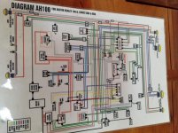
The brown goes from ignition/starter switch to control box (b) terminal , one white goes to the tach, one white goes the overdrive relay, the white/red goes from starter switch to starter solenoid. The third white also goes from starter/ignition switch to back of tach and loops from back of tach to the coil. At least that what my wiring diagram says for early cars and later. But I am no sparkey, so maybe someone else can chime in as well. As for me, when doing my BN 4 a while ago, I documented everything in great detail with photo, video, tags and blown up color diagrams to take the guess work out of things. But in your case sadly, someone else took the old harness off. Just look that diagram over again and blow it up larger to make things easy on your eyes, and maybe you will discover if you went wrong somewhere.
 

drambuie

Jedi Warrior
Offline
Hope this color diagram helps, maybe you can copy and enlarge.. image.jpg
 

Healey Nut

Luke Skywalker
Country flag
Offline
I think you have the harness through the firewall backwards .
Pics would help .
 

andrea

Jedi Knight
Country flag
Offline
Probably you have the focus on the starter switch-but this must be connected to the Ignition Key switch and from this then to the Coil
here you find a wiring diagram is for 100/6 but probably valid also for BJ7
https://picasaweb.google.com/112770819864514987162/SCHEMAImproved1006#5848216810819766242 (follow the arrow for more diagrams)
can be downloaded and then print- for my car I have print a large 4xA4 poster -this and the labeling of the wire helped me a lot
https://picasaweb.google.com/112770...MayJune2011endMayJune2013#5623699261090705922
DON'T forget to avoid the burning harness- NOT use the Battery - one self protected, 8-10 Amper, Current Supplier is sufficient for this work- and immediately Kick off- if a short occur
prefer the ones that can be rearmed pushing a button
 
OP
T

toxig

Freshman Member
Offline
That's a great wiring diagram, I will blow it up and compare it to the one I have in the Haynes manual.
I don't think this is a huge problem because there is no brown wire on the dash side of the firewall at all so it will just have to be extended. it just does not make sense why the wire does not come out on the right place.
I will try to post some pics.
Thanks
 
OP
T

toxig

Freshman Member
Offline
The harness is defiantly not through the firewall backwards because I have most of the dash wired up including instrument light fittings which are pre- fitted in the harness.
I will try to post some pics.
Thanks.
 

RAC68

Darth Vader
Offline
Hi Toxig,

I believe the dash harness my BJ8 Phase 1 is very similar to your BJ7. Hear is a map of the dash/engine-compartment/headlights that may help.
Dash%252520Headlight%252520Engine%252520Harness%2525201.jpeg

All the best,
Ray (64BJ8P1)
 

blueskies

Jedi Warrior
Country flag
Offline
This just does not sound right. If in fact the harness is installed correctly and various wires do not reach, you could definitely contact the vendor to ask them what's up. The new harness that just went into the 100-6 needed no wire extensions for the dash area. I did have to snip one wire and add a different connector on, but that was it.
 
OP
T

toxig

Freshman Member
Offline
Thanks for the help, everyone, and for the various diagrams that you have sent. Unfortunately none were specific to the BJ7 and so are not quite the same for the starter area. The diagram in the Haynes manual definitely does not conform to the harness that I bought from AH spares (which replicates the one that was taken out). So, if there is anyone who has just fitted a BJ7 harness and can advise or has a accurate BJ7 diagram, I would be most grateful.
Thanks again everyone
 

Keoke

Great Pumpkin
Country flag
Offline
What differences between a right hand drive and a left hand drive harness ?
Bob

I do not know the answer but it certainly may be a significant difference??? :encouragement:
 

Healey Nut

Luke Skywalker
Country flag
Offline
What differences between a right hand drive and a left hand drive harness ?
Bob
None of the major suppliers specify left or right hand drive for ordering harnesses so there should be no difference and why would there be the engine /lights/starter etc dont know wether it's left or right hand drive .
 

drambuie

Jedi Warrior
Offline
The only difference may be the dash wiring, dip switch, on the opposite side. But I would assume that part of the wiring loom can be inverted? Never really considered it.
 

John Turney

Yoda
Silver
Country flag
Offline
None of the major suppliers specify left or right hand drive for ordering harnesses so there should be no difference and why would there be the engine /lights/starter etc dont know wether it's left or right hand drive .
The one in the UK referenced earlier in this thread specified LH or RH. On this side of the Pond, they all assume LH.
 

CraigC

Jedi Trainee
Country flag
Offline
Since I now doubt the accuracy of the schematic I was using, I am deleting original post. :(

Early cars appear to have only two brown wires--from solenoid large battery cable terminal to regulator terminal A and from regulator terminal A to fuse box.
Power to light switch came from regulator terminal A1 in a brown/blue wire with a second brown/blue running from this same terminal of light switch to the ignition switch.
Apparently, these last two wires were changed to solid brown on the BN7, BT7 and BJ7 per diagram of GregW.

I suggest the OP look for any brown/blue wire at the voltage regulator and light switch in case the harness was made using the earlier color.

Sorry for any confusion from original post
 
Last edited:
Similar threads
Thread starter Title Forum Replies Date
M TR4/4A Position of wiring loom inside the trunk/boot area. ? Triumph 3
doc50 TR2/3/3A New Wiring Loom, No Clue Where to Begin. Triumph 12
doc50 GT6 TR3 Wiring Loom...where do I start?? Triumph 2
R 100-4 WIRING LOOM ???'s Austin Healey 6
H TR4/4A 4A Wiring loom quesstion Triumph 13
A bulbs in the speedometer for new wiring loom ? British Motor Corp 4
doc50 TR2/3/3A New Wiring Loom for TR3 Triumph 7
Schroeders Period Cloth Wiring Harness Loom Material Needed Austin Healey 5
L TR2/3/3A 3-way connector TR3A - wiring loom Triumph 2
1 Wiring Loom Cover Spridgets 9
T New Wiring Loom Soldering Restoration & Tools 25
angelfj1 Winter Projects - Wiring Loom Triumph 7
S wiring loom bj8 Austin Healey 7
M underdash wiring loom routeing??? Austin Healey 9
T TR6 Alternator wiring Triumph 3
B Land Rover Series 3 Wiring Diagrams Rover / Land Rover 0
J TR2/3/3A Wiring Triumph 11
71TR6 TR2/3/3A A TR3A wiring question Triumph 17
T 1971 Fuse Box and Wiring Triumph 7
tahoe healey Wiring Diagram for Fog Lights Austin Healey 12
P Wanted Wiring scraps Triumph Classifieds 14
olarson TR2/3/3A Horn Replacement Wiring Triumph 7
Sopwith_Camel horn relay wiring Jaguar 3
luke44 TR2/3/3A Calling all Wiring experts TR3 Overdrive Wiring ver A or ver B or are they the same? Triumph 8
K TR2/3/3A Wiring a voltmeter gauge to replace the ammeter. Triumph 1
B Steering Column Wiring/Sealing Austin Healey 1
timsgolf Coil Wiring Austin Healey 20
T Spitfire 67 MK2 Wiring Triumph 12
Joel Lester TR2/3/3A TR3 Wiper motor wiring and testing Triumph 5
P XJ12 Wiring diagrams Jaguar 1
Scotsman Wiring Diagram for 1966 BJ8 Austin Healey 3
J TR6 TR6 Hayden Pusher Fan Wiring Triumph 2
B TR4/4A Basic Wiring Question Triumph 35
C For Sale Center wiring harness for a 1959 Sprite Spridgets Classified 0
I Lotus Elite wiring diagram Lotus 6
K TR2/3/3A British Wiring alternator conversion kit question. Triumph 3
6 BJ8 Headlamp Wiring Austin Healey 1
S MGB mystery wiring plug MG 2
R TR6 Starter wiring question Triumph 6
R Spitfire Turn signal wiring Spitfire Triumph 5
B TR4/4A High Torque Starter Wiring Triumph 9
N For Sale Wiring harness 64-67 mk lll Spridgets Classified 0
J Wiring Harnesses Issues Spridgets 3
S Wiring Harness Replacement Spridgets 1
R Electric fuel pump wiring Spridgets 4
B TR4/4A Wiring Harness Triumph 6
R Wiring ??'s Spridgets 17
Healey Nut Rear Wiring Routing Austin Healey 2
7 General TR Wiring harnesses Triumph 5
Got_All_4 TR5/TR250 Wiring/Electrical Mystery Worked Perfect Then Not Triumph 5

Similar threads

Top