• Hi Guest!
    You can help ensure that British Car Forum (BCF) continues to provide a great place to engage in the British car hobby! If you find BCF a beneficial community, please consider supporting our efforts with a subscription.

    There are some perks with a member upgrade!
    **Upgrade Now**
    (PS: Subscribers don't see this gawd-aweful banner
Tips
Tips

New Tools in my shop, need some lessons

I must have read old instructions for the rear seal. I thought they still needed part of the scroll cut off first. I was planning on using the new rear main seal. It seems the simplest.
As to why I would do the work on my lathe, I have a lathe, I just want to learn how to use it and what to use it on.

Jerry
 
I will agree with TR3driver that I would never try to singlepoint (MAYBE with carbide?) but a grinder is about the only way to get the finish that you will want!
BillM
 
There are two different "modern" rear seal kits available. The one available from most vendors does require that the scroll be machined away and there seems to be considerable confusion as to how much to remove. Lots of folks have removed too much (it seems), resulting in leaks far worse than original.

As far as I know, the "new" kit (first available last year I believe) is only available in the US through TRF and ARE. It does not require the scroll to be machined away, and in fact retains part of the sealing function of the scroll. It adds a lip-type Viton seal that rides just outboard of the scroll area, on the smooth junction between the scroll and the flange.

Here are the installation instructions for the "new" kit:
https://www.tr4-racing.de/download/splitseal.pdf

I fully understand the attraction of doing it yourself; I bought a lathe & mill, etc for much the same reason. Still, as Dirty Harry said, a man's got to know his limitations. At the very least, I'd want to find an otherwise ruined crank to practice on.
 
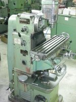
I seem to have found one of my limitations today. My milling machine has the cutter stuck in the head. I have hit pretty hard on the top of the spindle and it will not release. I put some oil down the threads today to see if it soaks the tight compression fit. Any ideas out there?

Jerry
 
If this is a Bridgeport style mill then that is correct- the R* collet is supposed to jam in there.
To free it you unscrew the bolt (about 3 turns!!)on top and hit it with a lead (or similar) hammer, the bit should then fall out.
BillM
 
:iagree:

Mine bears little resemblance to a Bridgeport, but works the same way (although the taper isn't R8).

The bolt/drawbar is important, though. Just beating on the spindle won't help. The idea is that the drawbar runs through the center of the spindle and into the collet that is gripping the cutter. So by beating on the partially unscrewed drawbar, you are actually driving the collet out of the spindle. If you didn't get the drawbar with the mill, you'll need to find or make a substitute to get the cutter out.
 
Can you post a picture of what the drawbar looks like. I got lots of stuff with the mill but I have not found anything that seems to work.

Jerry
 
The details will vary considerably with your mill. But here are a couple of Bridgeport types I found on the web:

75060630.jpg


Mine looks somewhat different, but I can't take a photo just now. It's basically just a long bolt, perhaps 2' or so with a big knurled knob on the top. The bottom is threaded for 2" or so, perhaps 3/8 NC.
 
TR3driver said:
... Seems like a no-brainer to me, especially given all the horror stories of seal conversions that leaked much worse than <span style="font-weight: bold">the original seal (which actually does pretty good if you set the clearances right instead of following the book).</span>

This is true. I set mine clearances according to the revised dimensions Randall shows, and have <span style="font-weight: bold">no leaks </span>from the rear main after about 1,500 miles of driving since the engine was rebuilt.
 
Jerry
You can't see the drawbar since it is inside the mill head. If the cutter won't come out that normally means that the drawbar is doing what it is supposed to do.
In line with the cutter and straight above it on the top of the machine (probably 18" above the cutter) should be a nut (guessing about 3/4") sticking up about 3/4". If you turn this nut the cutter should turn too.
Try turning this nut and tell us what happens.
BillM
 
I took the cutter out when I first got this machine and that was accomplished by loosing the nut on top of the head and tapping with a lead filled hammer. I then put in a different size cutter and tighted the nut. Must have tighted too much as tapping with a 2 lb sledge is not budging the nut and bar.
Back to the drawbar:
Do you pull out the threaded rod and put the drawbar in to take all the tapping abuse?

I added a picture of the machine I found on the web. IE: this is much cleaner than mine. The nut would be on top of the head , out of the picture.

Jerry
 

Attachments

  • 27801.jpg
    27801.jpg
    170.4 KB · Views: 83
Back
Top