• Hi Guest!
    You can help ensure that British Car Forum (BCF) continues to provide a great place to engage in the British car hobby! If you find BCF a beneficial community, please consider supporting our efforts with a subscription.

    There are some perks with a member upgrade!
    **Upgrade Now**
    (PS: Subscribers don't see this gawd-aweful banner
Tips
Tips

TR2/3/3A New engine mounts not sitting flat

71TR6

Jedi Hopeful
Country flag
Offline
Hello all,
Another question on my TR3A restoration.

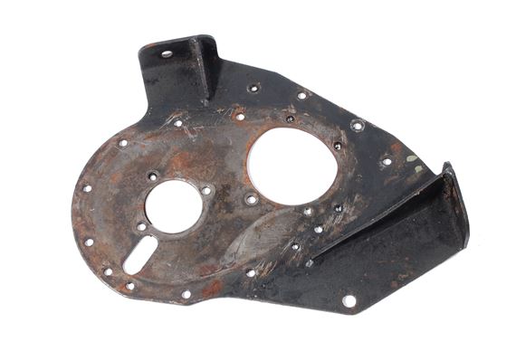
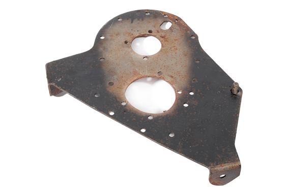
I just installed the engine with new engine mounts and it was a bear getting bolt holes lined up. It appears the angle of the engine mount attach point for the mount is different than the angle on the frame. It results in a gap as seen in the image.

IMG_1776.jpg

I don't recall having this much of an issue when I did my 6. Is this normal and will the mounts settle in eventually?

Ron
 
Did it sit off like that before you tightened the bolts? It may need to be shimmed.
 
There was a good 3/16" space on each mount. Both sides pulled in at the bottom when I tightened the bolts and had the same gap at the top edge.

Ron
 
Now I am confused. If the gap was all the way across the mount, what was holding up the engine?
 
Do you have a radiator with the crank hole? If you do does the hole line up with the crank dog?

The holes in the mounts may be in the wrong position. How did it look before you had the bolts installed?

David
 
I do recall seeing something like this once before and the problem was the front engine plate was for a TR4 which has different front mounts, could this be your problem?

Graham
 
+1 on Graham.
Ron, yes definitely something is wrong. I just did it a few months ago on my 3A and all was tidy. ISTR the shims being flat, not wedged, so if true that’s not gonna work either. Looks like you also have a small gap also at the front and above of the mount? Is the rear mount correct? If the front plate is indeed correct, it looks like the engine is tilted forward 5-degrees.
 
Can the mount be 180 out? Can the mount spin around and correct the problem. I think the studs are not centered so it might be the problem
 
The mount hole locations and the stud location are in the same location as the old mounts I removed from the car. Based on the pictures I took before I pulled the engine, I believe the orientation of the mounts is correct and not 180 degrees out but I'm certainly open to anyone's feedback whether this is indeed the case. Maybe the PO had them in the wrong way and they settled in to fit?

As far as the rear mount, I needed to mill slots in the mounting holes to move the transmission mount back since I'm using a later TR4 overdrive transmission I picked up that is slightly longer. That fits fine.

As far as a TR4 front engine plate, it's unlikely but given the pedigree of this car, it is possible. The engine number is clearly correct for my TR3A. What are the differences between a TR3 vs TR4 engine plate?
 
When you modified the rear engine/ transmission plate, did you also grind down some of the flange at the rear of that plate? This is the flange that sits up a good 1/2" on the rear of that plate. It does not seem that that much would make the difference you are having. But one does need to grind off the rear flange.
 
Charley, I avoided needing to grind off the rear flange you mentioned by milling the transmission mount holes into 5/8" slots to allow the mount to butt up against the flange and then milling the frame mount holes around 0.10" in the opposite direction to allow the transmission holes to match perfectly with the mount holes. There is no binding fore-aft on the engine/transmission.

Ron
 
I think Graham has a good point but the other way did you get TR4 mounts instead of TR 3. It looks' like the mounting holes are a bit off if you take the bolts out of the frame it would sit flat. Where did you get the mounts ?? Moss ?? If it did not sit like that with the old ones that would be the first place to check and compare. It looks like a half hole off and the mount would be the only thing to modify. Looks like you are moving along well send more pic.. Madflyer
 
I dug through my stash of parts and came across another engine plate and it is very different than the one on the engine- here is an image. I noticed immediately the pads appear to be much smaller (maybe better suited to the round TR4 mounts?) and have 45 degree clipped corners. Is this therefore a TR4 plate?

TR4mount.jpg

Here is a view of the engine plate and mount that is on the engine. The mounting pad on this is more rectangular and has a rounded pad corner. Does a TR4 engine plate have these characteristics?

TR3mount.jpg
 
Madflyer- to respond to your question concerning the engine mount possibly being for a TR4, the mount I have is Moss PN 810-011 which is for TR2-TR3B

I just found an image on Rimmer's site for a used TR3 engine plate and it looks like mine...

301251U.JPG


They also list a used TR4 plate that looks like what I suspected is the TR4 plate I have.

304711U.JPG
 
Has there been any frame damage or repair that could have caused this ?
 
Ken, you bring up a good point. The right front end of the car had suspension damage that I had repaired by a frame shop. They pulled the top of the shock tower back out along with the short frame section immediately behind the shock tower. I ended up replacing the lower fulcrum pin myself since that was mangled. The frame and shock tower are back to spec but it is possible the angled piece the mount attaches to the frame may still be out of whack. I wasn't able to find any specification on what this angle needs to be but I'll take some measurements tomorrow and see what I find.

From what I can see just looking at it, something is out by a couple of degrees and it is possible that could be on the right side. The engine settles into the middle and splits the error between the left and right side which would be why it is pulling up on both sides. A 0.1" gap on the top of a 5" long mount translates into just a shade over one degree and would explain the gap on the left side mount (which is the same on the right side) in the image I sent earlier.

I may have to machine one or more custom angled shims to correct this. I'm hoping I don't have to add 3/16-1/4" of shims since I'm not sure what else this will affect besides just raise the engine slightly.

Thanks everyone!
Ron
 
Hello Ron,

I just checked my front plate and mounts and yours is setup the same as mine and looking at the way the front plate is made I can't see how the angle where the mounts bolt on could be changed without completely destroying the plate so the only area that could be out is the angle of the frame. Looks like a wedge is the likely fix and you will be the only one who knows its there.

Graham
 
It looks like this could be solved by removing the mounts and elongating the holes in the lower plate downward. A flat washer on the bolt head would probably hide the elongation.
Bob
 
Thanks everyone. I'm going to figure out how to mill a couple 1 degree wedges today out of some bar stock. That should take the worst of the angled difference out of it and the rest will be taken up by the mount compliance (I hope).

I'll post what I come up with. Never a dull moment with these LBCs!

Ron
 
I just scowered the manual to see if there is any reference geometry to measure...no luck. The 2 checks I would do before going too far is to first look at the crank lug through the radiator to see where that sits. That is to get an idea if your engine is sitting too high. If it sits to high, you will have interference issues later in the build, so VERY important to check. Too low will cause contact between the steering tie rod and the crank extension.

Second is to install the frame cross brace to make sure it will not change the position of the frame.

Once you look these over you will be in a good position to decide how to handle it.
 
Back
Top