• Hi Guest!
    You can help ensure that British Car Forum (BCF) continues to provide a great place to engage in the British car hobby! If you find BCF a beneficial community, please consider supporting our efforts with a subscription.

    There are some perks with a member upgrade!
    **Upgrade Now**
    (PS: Subscribers don't see this gawd-aweful banner
Tips
Tips

General TR Instrument Faces

Now I was down to "buttoning up" the tach. After everything else I did, this is both easy and fun. Here is the quick and dirty:


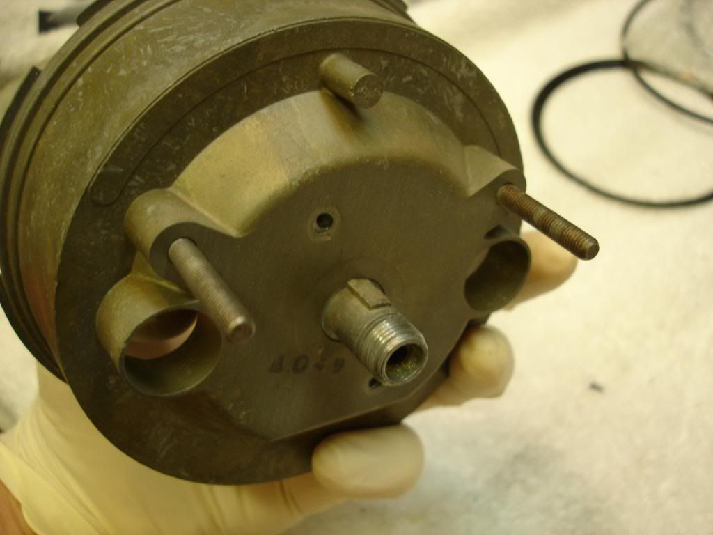
First, the assembly we have been calibrating goes back in the case. You will likely be confused, like me, as it can go in both the right way...and upside down. The key on the drive dog goes upward, as shown. The case mounting studs also go to the top.


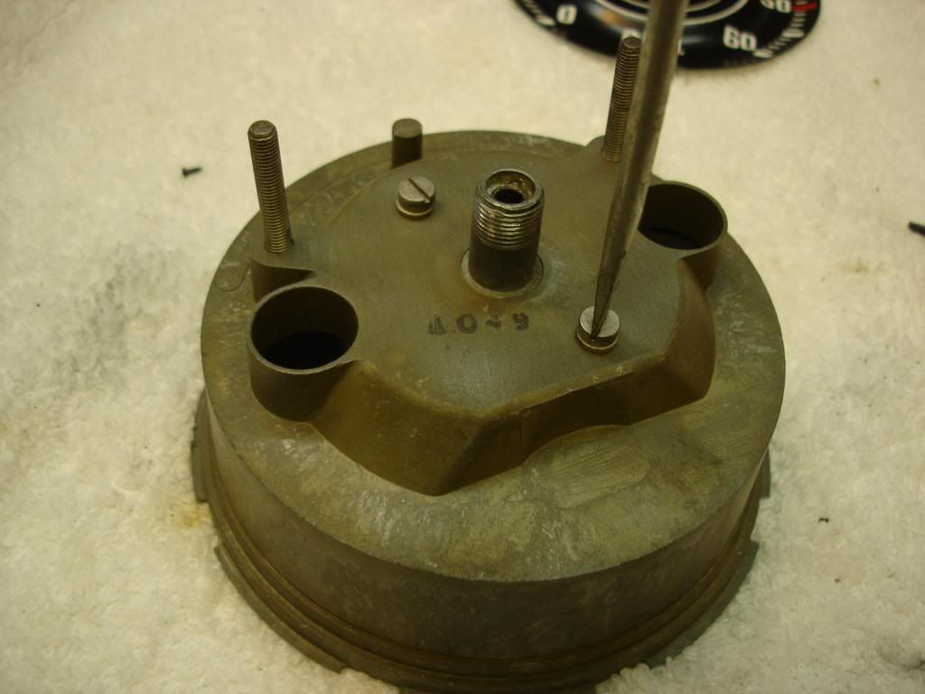
Secure the two screws with washers to hold the frame in the case.


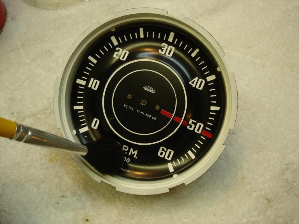
This is the last chance you will have to make sure the unit is dust free. I blew with air and then dusted the face with a very soft brush. Ignore the fact I have no needle on at this point...yours should be on.


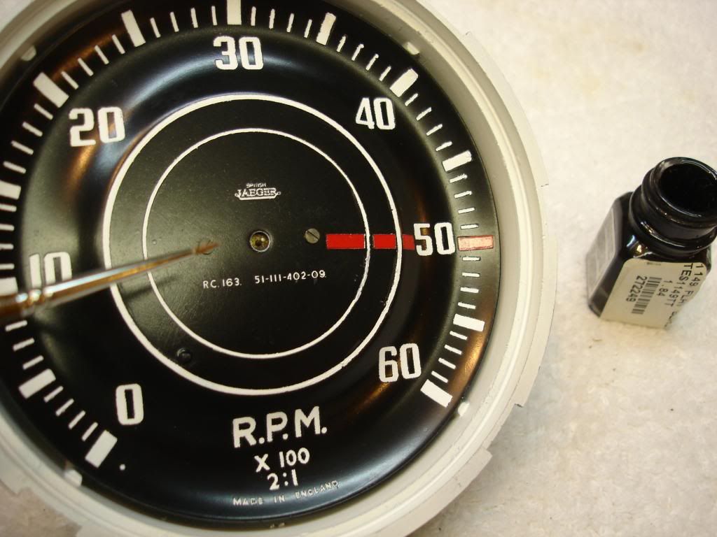
I did a final touch up on anything that needed paint. The face mounting screws were a bit tarnished, so they got a dab of black paint, along with the needle stop post.


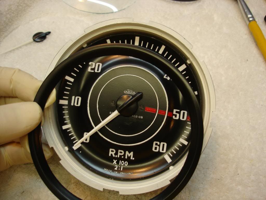
This is the reflector ring that goes in against the face. Make sure the back side is white, or little light will make it to the instrument face. Now we have to clean the glass.


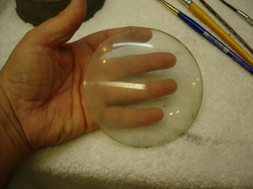
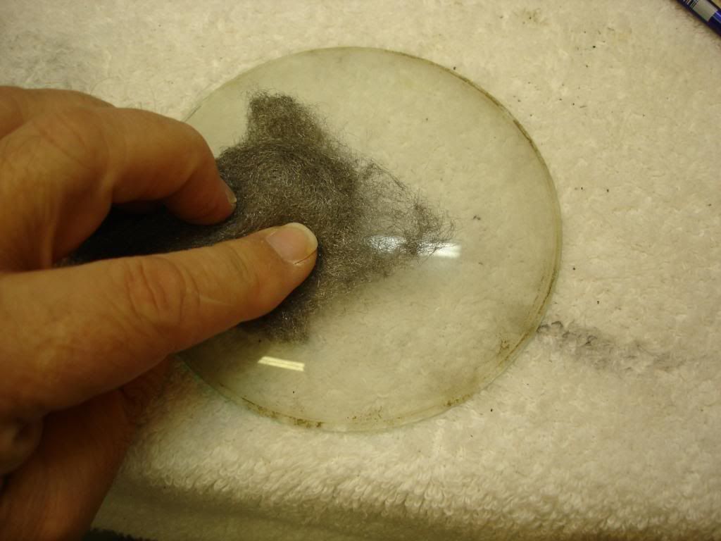
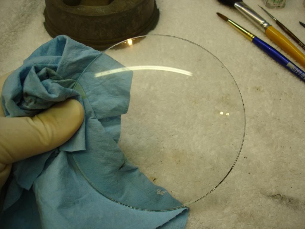
Mine started really nasty. The car sat outdoors for 25 years, and there were water marks showing the tach had filled at some point. I removed the scale with very fine steel wool. I polished a few scratches with a buffing wheel on a drill press, and then finished with windex.


Now I broke out the new bezel and seal from Nisonger's. They charged $120 for the 6 bezels and seals. Highway robbery for what you get...but they have a corner on the market, so I had to fork over the dough. Maybe one of you guys have a cheaper source you can let us know about.

 
John, that is an excellent write up !

This thread is great. I strongly encourage you to write this up in a document that can be circulated. You have shown a lot of great information here that will be of value to more than just Triumph owners!

Great Job !
 
The rubber seal fits in the gap between the glass and the case, so it touches both. This is important, as it seems like it should go farther outward, just touching the case. It must touch the glass to protect it. Trim the end for a good fit.


The bezels come with the locking tabs straight out. The tabs will need to be bent inward. Start this with a large set of pliers, bending about 30 to 45 degrees into each tab.


Then carefully place the bezel over the tach. Care must be used to keep the rubber seal in place, all the way until the bezel is fully locked. The little thing makes a run for it at every opportunity! Once the bezel is in place, flip the tach face down on a padded table. You now must finish bending the tabs the full 90 degrees to lock the bezel in place. Work around the bezel using a dift or screw driver and only hand force. Do not hammer, as you could knock the needle off. A firm push is all it takes since you already started the bend. It also helps if you rock the tach towards the tab you are working on, so the bezel is on the table, instead of just the domed glass on the table.


And...the tach is done and ready to go in storage for the next couple years. One down, and 5 to go! Here is a before and after shot...


Next I move to the speedo...stay tuned!
 
John
Great job! I have a box full of gauges when you are done with yours. Actually if you need some good faces I have several gauges that don't work but look nice.

Marv
 
Marv, I should have checked with you before I got started on this saga 5 months ago! I still might have to for some of the internals on the smaller gages as I get to them. The faces in the photos above are actually from your donor car. I didn't want to destroy the original TR2 faces so I had them for comparison as I went.


Edit:

Before I get going on the speedo rebuild, I just had a revelation while calibrating the speedo. When I said you need a big a%$ magnet...I was wrong. After reading Anthony's speedo write up, I had ordered 4 tiny rare earth magnets, just in case my gous/de-gous failed. Here is a picture of these tiny magnets:


They are 1" x 1/4" x 1/16", and on the very strong side as magnets are measured. Here is the revelation...

Only one of these rare earth tiny magnets is enough to calibrate our speedo/tachs!!

Just a single touch and slide is enough to strengthen the speedo magnet, and holding it 1/4" away from the spinning rotor is enough to weaken it. So for $1.50 in magnets, you can calibrate your tach and speedo!
 
Last edited:
Time for the speedo installment.

The indicator portion of the Smith's speedos is identical to the tach. In fact, those parts are interchangeable. The difference is the addition of a gear on the spinner magnet, which is what drives the odometers:


The large brass disc on the spinner is the worm gear for the odometers. There are 2 gears that slide into the housing to mesh with the worm gear...one on each side. One is for the top trip ododmeter, and the other for the lower mileage odometer.


These gears have little cogs on the opposite end, which wobble...


The wobbling cogs transfer this wobble to an arm...


Which simply pushes on a brass ratchet gear that you can see on the end of the number wheels...


The brass ratchet gear spins the shaft for the number wheels, but the wheels are held from spinning constantly by the shape of the edges of the wheels, which catch on these little reeds on the housing...


The right side of each number wheel has a ratchet that catches the reed every digit...


And the left side of each number wheel has only a single ratchet, which lifts the reed to free the number wheel to it's left...


So, the whole process is that the worm gear on the rotor turns the 2 odometer gears. Those gears have an eccentric shaft on the opposite end which wobbles an arm. The arms ratchet the number wheels one tooth at a time. The "tenth's" digit number wheel spins constantly, and every whole turn...or 10 digits...it frees the reed holding the "1's" number wheel. Every full turn of the "1's" wheel frees the "10's" wheel for one digit. And so on down the wheels.


And it is as simple as that!

The problems you will run into is that the grease on all these tiny parts hardens with age. Once hard, the little gears will strip, or the magnetic rotor will freeze and fray the flex drives. The odometer and magnetic rotor assemblies need to be cleaned and re-greased every 10 years to prevent damage. If you carefully clean and regrease every 10 years, there is not much that will wear out. If you wait too long...several parts will be permanently damaged. The parts that can break if you don't regrease include, the flex cable (if you are lucky), the gears, the reeds, and the ratchet wheels. If any of these are broken, with the exception of the flex cable which is sold new, it's time to call Marv for spare "old-old-stock" parts.

So, now that I have the basics...here goes my speedo rebuild
 
Last edited:
Speedo Disassembly...

My TR2 speedo had sat out for 25 years, so the numbers were flaking. The numbers are silkscreened on foil strips, which are wrapped around the number drums. I have not found replacement foil, although I have found suppliers for decals. I chose to use the "better" number wheels from Marv's donor car. They are still bad...but at least they are consistent colored and not flaking.


If anybody finds a source for new number strips...please let us know.

The initial disassembly is identical to the tach...so I won't bore you again. Once you have the assembly out of the case, needle removed, and face removed, you are looking at this...


The long rod is the reset shaft for the trip odometer. I have 4 old Smith's Jaeger speedos, and all 4 had broken reset shafts when I got them. There is a hole through the shaft to hold the reset knob, and the shaft breaks at this weak point. I will cover how to fix the shaft later. The reset shaft slides out once you pry the little cotter key off. These are the parts that slide off with it. Set them aside.


Each side of the housing has a toggle arm, held with a clip. Simply lift and slide the clip to remove. There is a small sping, which has to be unhooked before removing each arm.


This is the trip odometer arm...it is distinct in that there is a bar at the top for the reset shaft to press while you spin the numbers to zero.


The mileage arm is shorter and has no bar at the top...


Now, by removing 4 screws, the housing can be separated from the needle/odometer plate...


The trip odometer assembly falls free at this point...


Once again, as with the tach, the aluminum disc is only being held by the fragile clock spring. Support the disc until you place some tape to hold it from getting "sprung"


The 2 drive gears can now be removed. If the grease is hard, you may have to tap them out. Note that the gears are plastic, so look for a broken tooth at this point. You need a replacement if you have lost a tooth...


This shot shows the gear, and the eccentric shaft coming off the end.
 
Now the rotor can be remove by reaching through it to the retaining plate, just like on the tach...


Now you are down to the bare housing. All the black grease has to be removed.


Now, back to the number wheels. We'll start with the smaller, trip wheel. This is what you are looking at...


(you'll notice it seems like I'm being obsessive with the number of pics and angles. Although the wheel assemblies are simple, there are a LOT of small parts. You will need as many picks as posible to avoid confusion when it comes time to reassemble!)

This is the end of the wheel with the brass ratchet gear. Press the brass gear towards the numbers, and this clip plate can be pulled up and out...


Now the shaft can be slowly removed, carefully removing each wheel one at a time. There is a small brass washer between each wheel...remove these now, or they will fall off the number wheel when you are not looking. They are easy to loose...


And this is what you end up with...


Notice there is a small keyed washer between EVERY wheel! Lay them out as I have and you will not have nay trouble when it comes time to reassemble.


Now we move onto the mileage wheel. It is almost identical. Remove the clip on the brass gear side by pressing the gear inward. Note the clip plate is shaped differently...


Here is another difference. This plane plate is on the "one's" digit wheel side. Its purpose is to prevent the ones from turning at the same speed as the tenth's wheel on the trip odometer. Notice it has a single ratchet, so it lifts the reed for the one's wheel once each revolution.


And you are now fully disassembled! Here is what you should be looking at...


And of course, do not be rough with the needle plate...the loss of the clock spring is a deal breaker!

 
Now is cleaning time. All the little parts need to be carefully cleaned. Lube them with a small amount of grease or light oil. If you won't be driving the car much, then I would lean towards oil, as it is less likely to turn rock hard. For normal driving habits, I prefer a dab of grease.

Items to take care to check...

1) Look at the 2 plastic gears. They are usually the first to loose a tooth if the grease turns to glue.

2) Look at the 2 toggle arms. One arm pulls against the ratchet gear, the other pushes. There should be a very sharp burr to interact with the brass gear. If the gear froze up, the burr can wear off.

3) Look at each and every tooth on the brass ratchet gears on the wheel drums. There are a lot of teeth, and a single bad tooth will stop the wheel for ever and a day. The ratchet teeth must be perfect.

4) Check the needle bearings on each end of the aluminum disc. They must be straight and not corroded. Use only very light oil, or nothing, to lube these 2 needle bearings.

5) The little reeds that stop the number wheels. They are fragile, and if a wheel jams with the drive shaft, they will break. They must be in good shape, or the respective number wheels will spin continuously. Also make sure they are straight and not bent at any angle to the base plate.

6) The aluminum disc is realy pretty weak. It must rotate in a single plane. In other words, it must not "wobble" when you turn it. Just a little pressure in the right direction will straighten it, if it does wobble. A sign of a bent disc is a speedo needle that "bounces" slightly.

Time for reassembly.

Simply reverse the order we took everything apart. I'll keep it to a concise pictorial.
 
Last edited:
Start by assembling the mileage wheel. Start at one end and add a wheel and work your way accross. Use caution not to force anything, as the reeds tend to hang up . Once together, use a small screw driver to set your mileage where you want it. Gently press the reeds below the wheel you want to turn, and spin the numbers. Work on only 1 wheel at a time, and do not be forcefull on the reeds.


Don't forget there is a washer for each of the drive gears...


Use plenty of grease on the drive gears...but that is the only place to use a good bit. Everything else is sparingly or not at all.


If there is a hard part to this whole assembly, this is it. The tiny springs on the toggle arms have to feed through the number wheel assemblies. Be patient...walk away if you get frustrated! I finally had to fashion a hook to pull the springs through. Even then it is tedious at best.


Don't forget the arm retaining clips...


Now the trip wheel. Three of the needle plate screws hold the trip assembly.


Remember the broken trip reset shaft? Now it's time to address that. My choices were to call Marv and wait a week, or fix the one I have. I decided to go the quick route. I cut about an inch off the end, after measuring exactly where the hole would have to be. I then welded an extension, drilled the new hole, and contnued the speedo assembly...


Note you feed the shaft from the top, so the toggle arm has to be moved out of the way...


And it's done! Next is the face plate, the needle, and time to recalibrate...


Speedo Recalibration

For those that skipped ahead, I learned that it only takes a small rare earth magnet to calibrate the speedo. After smashing the tach face with the mutha magnet, I HIGHLY recommend you use the smaller magnet for the procedure. It's....well....more civilized when every knife and screw driver in the shop is not flying at you from every direction.

So, to recap, you will need:

1) a way to spin the speedo at a steady speed. I used a drill and a spare flex drive cable.

2) A stop watch. I used an iphone.

3) A SMALL!!! rare earth magnet.

Here is the magnet I used...$1.50...


Here is the set up I used to spin the speedo. You will notice I have a C-clamp by the drill. When you want to weaken the rotor magnet, it has to be spinning so it sees reversing poles. I use the c-clamp to hold the drill trigger at a reasonable speed. The trigger lock on the drill was WAY too fast for the speedo.

Notice also that I always have the speedo oriented as it will be in the car. The needle is counter weighted to balance at the pivot...but over the years I do not trust the counterbalance to be perfect. So orient the gage the way it will be mounted.


Here is the synopsis of how this works. I will be making a couple assumptions that I am sure many will not like. Please remember there are many ways to accomplish this process. I am inherently lazy, so this is the easiest I could think of. There are likely more accurate...but more time consuming ways to do it better. Feel free to attempt them if you want...and let us all know how it works.

1) Remember how we set the needle to the little dot on the tach face at about minus 500? There is a similar dot for the speedo at about minus 5 mph. It is essential that you start with the needle set for this dot when the clock spring is unwound. The dot is more important on the speedo than on the tach. Just set the needle and forget about changing it.

2) In Anthony's write up, he recommended a drive test to calibrate. I'm not going to do that. I will make the assumption that the odometer is geared correctly. I will calibrate the speedo to match the odometer reading...and I will be happy with that! In actuality, the speedo will be inaccurate by the same amount that the odometer is inaccurate. I can live with that. I did the same thing on the TR3, and it amounted to a 1% error. Again, I am happy with that small of an error.

3) Remember the game you always play on a road trip, where you hold exactly 60 MPH and time how long it takes to travel a mile? That is what we will be doing. We are going to spin the speedo at exactly 60 MPH using the drill. When the trip odometer passes .1 we will hack the stop watch. After holding the 60 MPH for exactly 60 seconds, we will stop the drill and read how far the odometer registered. One minute should be exactly 1 mile.

There are two possibilities...well three, since you could be right on for the first try. But that is never my luck.

If the distance travelled is less than 1 mile in 1 minute: The speedo is reading to fast. We need to reduce the rotor magnetism. Do that by attaching the c-clamp to the drill trigger to spin the speedo while you place the small rare earth magnet 1/4" from the spinning rotor for 5 seconds.


If the distance travelled is greater than 1.0 mile in 1 minute: The speedo is indicating to slow. We need to strengthen the rotor magnet. Touch the rare earth magent to the back of the rotor magnet and slide it outward and off. I guarantee it is now too strong, so after the next timed run you will surely have to repeat the de-goussing step.

Repeat this process until 60 MPH indicated gives you exactly 1 miles travelled.

Once you have checked the accuracy of the speedo at 60 MPH, double check it by holding 30 MPH for 1 minute and see how far the odometer travels. It should be exactly .5 miles. If it is off noticeably, then the clock spring pre-load is off. You likely missed the dot in the first step. Just move the needle a tad in the direction it needs to go...and start over.


One point to note...if the needle "bounces" consistently a couple MPH while you are trying to hold a steady speed...the aluminum disc is likely bent. Use a screw driver to gently bend it straight.

Here is my finished speedo. I started with the odometer at zero, so you can see exactly how many trials it took to get it calibrated...one mile per trial. 22 trials.


Oh, installing the speedo in the case is exactly like the tach, with the exception of this felt seal for the trip reset shaft. Don't forget it!


And finally, the starting point, for old times sake:


I'll be taking a break before I tackle the small gages...
 
Last edited:
I know that for every one of you that has an interest in this thread, there have to be 10 thinking "geez, what a long boring post".

I decided to elaborate so much because I studied this junk for 5 months trying to get all the info I could. There are very small bits and pieces located in different forums...VW, Chevy, etc....but it is simply not available in any one location. The big companies are extremely tight lipped when it comes to how this stuff works. Even Anthony's write up is frought with errors. I loved reading it until I got to the part that said to "glue magnets onto the rotor", and I realized he was just guessing.

I write this for those that follow that enjoy doing their own work, and just need the "know how" to make it happen. Plus, I know I'll forget all this by the next restoration...what is the first thing to go when you get old??
 
Last edited:
John- Boring? Are you nuts?! This is really cool, excellent stuff, thanks for posting. I have one or two speedos with busted reset arms, and until now I've ignored them. I may continue to do so, but this gives me hope that I know at least one person who knows how to fix the problem!
 
All of my dials resemble those in the pictures you keep showing

6179775482_e903b47049.jpg
 
I know that for every one of you that has an interest in this thread, there have to be 10 thinking "geez, what a long boring post".

This is NOT boring at all !

As I mentioned earlier, I REALLY hope you will write your own summary document and post it online so your work is not lost. Threads roll off the bottom of a message board and are too easily forgotten. This is excellent instructional information !
 
I think this is one of the most interesting topics I have seen here, I am willing to tackle about anything, but even after reading the excellent tutorial and information don't think I would even attempt to try refinishing an instrument face like you have done, I would try the mechanical bit, and have done a little bit of cleaning and repair on speedos and tachs. As one of the other posters suggested, I too stuck some tiny rare earth magnets on my speedo to get it back up to snuff when it read way too slow.

But man, that instrument face stuff is truly amazing work.
 
Thanks to all of you for the support. The goal is to keep as many of our old cars working for as long as we can, by helping each other out! JP, your gages look dirty, but I bet the faces will clean right up with a gentle dusting. They really look pretty good.

It kills me with my old TR2 that someone could just park a car in a back yard, uncovered and in the weather for over 25 years. There should be a law against that kind of abuse. I actually talked to the gentleman that owned it while it sat, and he sounded upset that the guy that bought it from him had sold it. He said "I really hoped he would fix it back up." He had no idea what he did to it. But, that's why we have the forum! As long as I'm still around, this old girl will be back on the road...eventually.

Doug, I could do an updated article, but I'm not really sure how to post a large document. I did learn that after a couple weeks, this thread will pop up under a Google search. Some of the old threads I read for info were over a decade old. So, as long as they don't shut down this forum (God forbid!!), this will be around for those who follow!

Thanks again for the support...I'll be back when I get rolling on the small gages. As you can tell from the pics, I have horns to fix next. I needed to get some of these instruments finished to get more work table space...
 
John,

Wow. I suppose I'm one of the ones interested, but I hadn't looked at this thread for some time. Today I couldn't stop reading. The thread is truly interesting. I'd love to see all that in a single document that I could unfold and have at my side when I dig into mine. I thought I was going overboard when I took faces off un-working gauges, cleaned them up and re-installed on working ones, but you've taken it to a whole new level. I had no idea they could be calibrated so easily. Also, I'm impressed that your dwell meter was accurate, as I tried several and finally used my o-scope on the coil+ -but for a different reason.

I have been telling everyone that I have taken apart every nut, screw and bolt in my TR3 restoration -but it's a lie. I have not taken (all) the instruments apart as far as you. Yet. Now that I see what's involved, I might start with the old ones I have. I'd really like to have a little more accuracy in the tach and speedometer. I have been taking them out and spraying wd40 and silicon through them every couple months -when they start bouncing terribly. I've been afraid to take them apart so thank you for posting the details.

I will not attempt to respray the faces. Your work is impressive.
Thanks again, Jer (if you make a single document, please let me have a copy)
 
Hi John,


Thanks for sharing with us this information and for the time invested for our pleasure and knowledge. Some months ago, you did the same with the sidescreen re-covering procedure, and thanks to your excellent posts, I have now a superb pair of them.


I have sent to you an pm, regarding the possibility of printing a speedo face in km/h, which Iā€˜d like to offer now to my TR3A.


JesĆŗs
 
Back
Top