-
 Hey Guest!
British Car Forum has been supporting enthusiasts for over 25 years by providing a great place to share our love for British cars. You can support our efforts by upgrading your membership for less than the dues of most car clubs. There are some perks with a member upgrade!**Upgrade Now**
(PS: Upgraded members don't see this banner, nor will you see the Google ads that appear on the site.)

Tips
- We have a special forum called "Member Articles" where you can submit actual articles for consideration for publication. Learn More
- Don't have an Avatar? If not, your avatar will default to the 1st character in your username. Go into "Account Details" to change your Avatar.
- Some basic forum navigation info: click
 Hey - did you know if you click on the title of a thread it will take you to the first unread post since you last visited that thread?
- Hey Guest - Is your British Car Club in our Clubs database? If not, send me a PM - Basil

- Looking for a local club? Click the "Clubs" tab above and browse hundreds of clubs world-wide.
- Add Android or iPhone APP: click
- Did you know - any picture or video you add in your posts in any marque-specific forum will also get added to the Media Gallery automatically.
- A few more tips about posting and replying: click
- Hey there Guest - be sure to keep your profile page up to date with interesting info about yourself: learn more
- More tips and tricks on Posting and Replying: click
 but were afraid to ask:
  STOP!! Never post your email address in open forums. Bots can "harvest" your email! If you must share your email use a Private Message or use the
  smilie in place of the real @
- Want to mention another member in a post & get their attention? WATCH THIS

- So, you created a "Group" here at BCF and would like to invite other members to join? Watch this!
- Hey Guest - A post a day keeps Basil from visiting you in the small hours and putting a bat up your nightdress!
- Hey Guest - do you know of an upcoming British car event?
 Pretty Please - add it to our Events forum(s) and add to the calendar! >> Here's How <<
- Hey Guest - you be stylin' Change the look and feel of the forum to fit your taste. Check it out
- If you run across an inappropriate post, for example a post that breaks our rules or looks like it might be spam, you can report the post to the moderators: Learn More
- If you would like to try some different "looks" or styles for the site, scroll to the very bottom, on the left and click the Style Selector.
You are using an out of date browser. It may not display this or other websites correctly.
You should upgrade or use an alternative browser.
You should upgrade or use an alternative browser.
General TR Block Crack Repair
- Thread starter CJD
- Start date
tomshobby
Yoda
Offline
Now, on to the fix. You will need a drill press of some kind to insure you drill the hole perfectly aligned. The block goes on top, and I used a "sticky" tape to keep it from shifting once it was aligned.
If you use a drill press to make a hole, it is only logical to use the same press to start the tap. It is the best way to make sure the alignment is perfect. They provide tapping fluid that really works well, and I finished by hand.


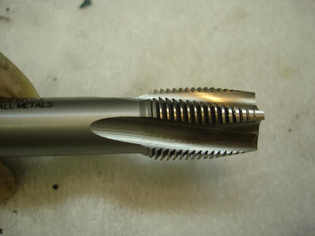
John, Since you seem to like things like this you might like to know what that dimple on the tap is for. It is for a center taper to use as a guide. T-handles for taps also have them. To use it have the work piece clamped in place and then drill the hole or if it is an existing hole use the center taper to align the drill head to the hole. Then with just enough pressure to follow the tap use a tap handle or wrench to turn the tap. This can also be used with reamers.
They are called "Buttress Threads"

Offline
I know from the PO that the engine was rebuilt, and I have little doubt that a crack like this is the result of lifting the block using the studs without the head to align them. I may be wrong, but that seems the only explanation.
Very interesting post, but a block can be so weak that lifting from a stud can crack it? I have my engine apart on a stand and want to lift it off and put it on a table. I planned to use a chain on the studs. That's really a danger?

OP
CJD
Yoda
Online
Tom...I can see 2 cracks on your block, one downward and the other right in the pics. No matter, the insert should be perfect for it.
Tom 2...that's interesting. Now I'm going to have to find a center taper to add to my tool collection!
KHV...I don't think we have definitive proof, but the general consensus is that lifting with the studs puts a lot of leverage on the end studs, and there is not much meat there to take it. My TR3 engine had never been rebuilt, and the stud threads were fine. This TR2 engine had been rebuilt by the PO, and it had the crack. It's very tempting to lift by the studs, as they are convenient...but it could cause the cracks.
Tom 3...the motor is back together, but it'll be at least a year before it gets tested...stay tuned!
pa297pass
Jedi Trainee
Offline
A question for John and others about lifting a TR3 / TR4 engine and transmission.
Do you think it is safe to lift a fully dressed engine and overdrive transmission using the head studs with the head fully torqued down and the chain sling fastened to two of the studs?
I guess its a moot point as that is how I lifted the engine and trans out of my TR4, but would like opinions anyway.
Thanks!
Matt
luke44
Jedi Warrior
Offline
This is one of the best documented repair procedures I've read here.
I'm very interested in how the engine holds up after the repair. Please keep us updated after it's assembled and back on the road.
Thanks.
Tom
Agreed, And, I hope I never have to use it!!
After a long research and preparation I finally started block crack repair.
Thanks to the magnetic base drill I was able to put insert in a problem stud hole without taking engine out. Positioning the drill and figuring out the countersink depth was the hardest part.
Now the only problem I have is how to file insert to be flat with the block without scratching the surface around it. I only need to file about .003-.004”. Any ideas anyone???
Below is couple of pictures taken thru the process.
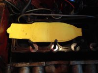
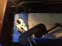
Template to see if magnetic drill will work (not to much space, studs removed on one side, lower studs holding the liners so electromagnet don't pull it

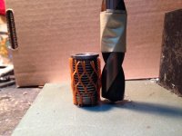
Insert and drill marked for depth

Using the stud as guide for position.

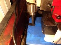
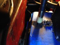
Drilling

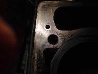
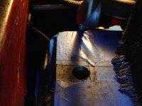
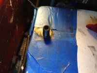
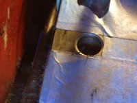
Hole with countersink

The way leveling was done

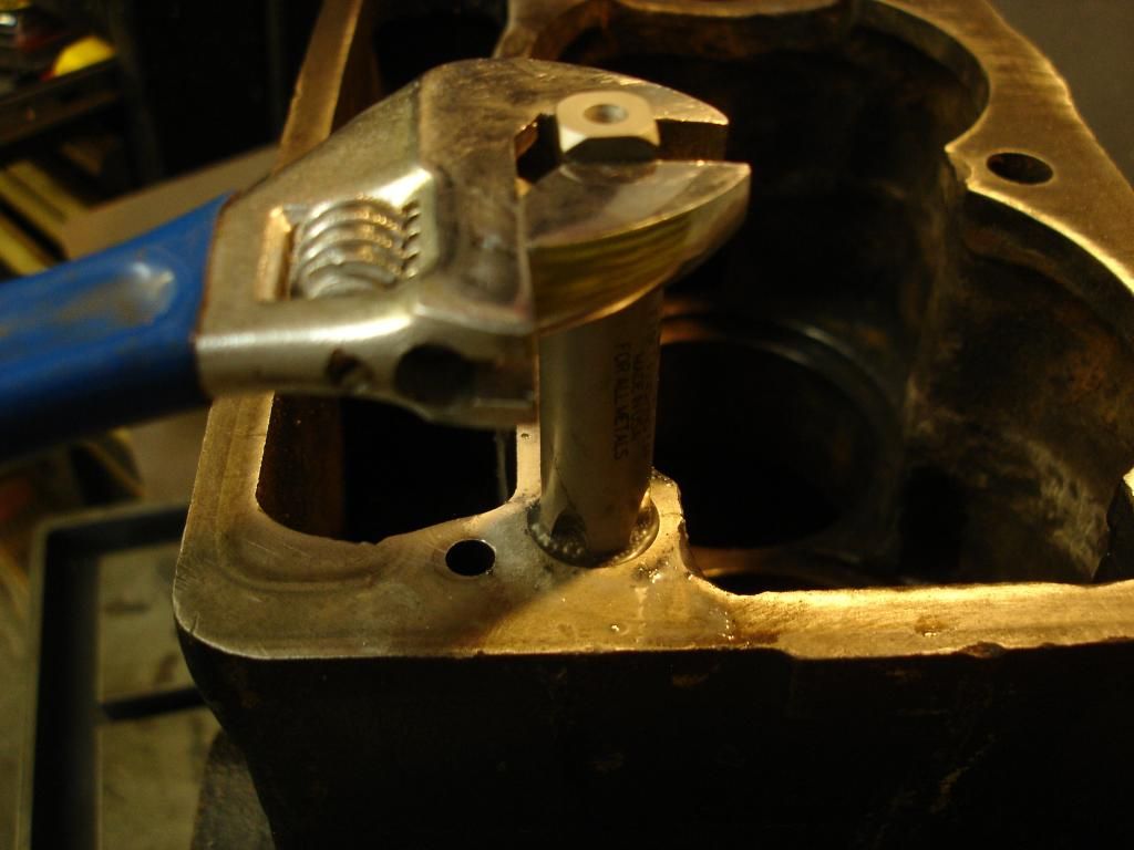
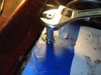
Using the drill to start the tap

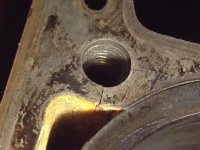
Threading

Insert installed with install tool on it

Jig to drill the locking pin hole

Thanks to the magnetic base drill I was able to put insert in a problem stud hole without taking engine out. Positioning the drill and figuring out the countersink depth was the hardest part.
Now the only problem I have is how to file insert to be flat with the block without scratching the surface around it. I only need to file about .003-.004”. Any ideas anyone???
Below is couple of pictures taken thru the process.
Template to see if magnetic drill will work (not to much space, studs removed on one side, lower studs holding the liners so electromagnet don't pull it
Insert and drill marked for depth
Using the stud as guide for position.
Drilling
Hole with countersink
The way leveling was done
Using the drill to start the tap
Threading
Insert installed with install tool on it
Jig to drill the locking pin hole
Attachments
-
 template.jpg59.2 KB · Views: 321
 -
 1.jpg54.8 KB · Views: 306
 -
 0.jpg41.2 KB · Views: 308
 -
 4.jpg54.3 KB · Views: 312
 -
 5.jpg54.9 KB · Views: 118
 -
 6.jpg30.7 KB · Views: 303
 -
 7.jpg59 KB · Views: 308
 -
 9.jpg53.3 KB · Views: 303
 -
 10.jpg59.4 KB · Views: 308
 -
 11.jpg42 KB · Views: 312
 -
 cs.jpg52.8 KB · Views: 307
After a long research and preparation I finally started block crack repair.
Thanks to the magnetic base drill I was able to put insert in a problem stud hole without taking engine out. Positioning the drill and figuring out the countersink depth was the hardest part.
Now the only problem I have is how to file insert to be flat with the block without scratching the surface around it. I only need to file about .003-.004”. Any ideas anyone???
Below is couple of pictures taken thru the process.
Template to see if magnetic drill will work (not to much space, studs removed on one side, lower studs holding the liners so electromagnet don't pull it
Insert and drill marked for depth
Using the stud as guide for position.
Drilling
Hole with countersink
The way leveling was done
Using the drill to start the tap
Threading
Insert installed with install tool on it
Jig to drill the locking pin hole
OP
CJD
Yoda
Online
I like that magnetic drill!
A decent flat file will lower the top of the insert. I started using tape to keep from scratching the surrounding deck, but after a few minutes you get the feel of the file, so the tape isn't necessary. I changed the angle frequently...but that may be hard for you with the engine in the car.
A decent flat file will lower the top of the insert. I started using tape to keep from scratching the surrounding deck, but after a few minutes you get the feel of the file, so the tape isn't necessary. I changed the angle frequently...but that may be hard for you with the engine in the car.
Hi,
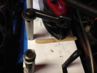
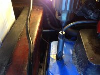
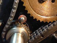
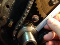
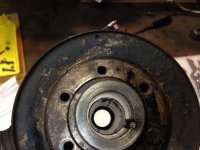
Please tel me if this is a mistake of previous owner, two thinks are wrong:
[FONT=Times New Roman, serif]1.fan pulley timing mark is not opposite (180 degree) the crankshaft key
2. the chain gears are not lining up perfectly
See the pictures


 [/FONT]
Please tel me if this is a mistake of previous owner, two thinks are wrong:
[FONT=Times New Roman, serif]1.fan pulley timing mark is not opposite (180 degree) the crankshaft key
2. the chain gears are not lining up perfectly
See the pictures
Attachments
tomshobby
Yoda
Offline
Buttress threads are actually quite common for vices used on drill press and mill tables and other uses in a machine shop. They are good because the pressure from the threads does not spread the part and cause cracks.
I also noticed in the pics of the tap that it was being turned with wrenches but not supported with a center point to keep it true to the drilled hole.
I also noticed in the pics of the tap that it was being turned with wrenches but not supported with a center point to keep it true to the drilled hole.
TR3driver
Great Pumpkin - R.I.P
Offline
Yeah, but that "stitch" insert does not have buttress threads. With buttress threads, the load bearing surface is perpendicular to the axis, while the stitching threads have it actually slope the other way. That's what causes the insert to actually grab the sides of the hole and pull them inward; while a buttress thread just doesn't push them outwards.Buttress threads are actually quite common for vices used on drill press and mill tables and other uses in a machine shop. They are good because the pressure from the threads does not spread the part and cause cracks.
Very hard to see in the insert photos, but you can see it in the bottom row of threads on the tap photo that John posted (repeated here)
Here's a drawing of a buttress thread for comparison

Got_All_4
Luke Skywalker
Offline
There is also a product called Time Sert. https://www.timesert.com/ . I've used these for years. They are very thin and allow you to go to full torque. Great for aluminum. Very similar process.
OP
CJD
Yoda
Online
Just a follow-up.
The engine is running, and no more sign of any leakage at all. The insert appears to be doing it's job very well! Since the original post 2 more owners "rented" the kit and saved a couple more old blocks. I am down to only a single insert left...which made the investment less formidable for all that needed it!
I'll post again when/if the final insert gets mailed out to save one last block. Whoever gets it this time gets to keep the kit!