• Hi Guest!
    You can help ensure that British Car Forum (BCF) continues to provide a great place to engage in the British car hobby! If you find BCF a beneficial community, please consider supporting our efforts with a subscription.

    There are some perks with a member upgrade!
    **Upgrade Now**
    (PS: Subscribers don't see this gawd-aweful banner
Tips
Tips

TR2/3/3A Beginning the TR2 Bodywork


That is it for mounting a rear wing.

The seams can be "coaxed" up to about 1/16" using a broad head hammer where needed. Notice the bottom of the front actually aligns with the tub pretty well. You have a small amount of flexibility with this alignment, as the stone guards can be installed to cover it. I was not so lucky on the right rear wing, though!


On the right side, this is some metal that has stumped me for 2 years. Kept looking at it and wondering what could have been "clipped" here. Luckily, it finally dawned on me...


It is the prop rod bracket! Duh!


The bracket was unusable on the original tub, but it was good enough to take measurements to fashion a "new" bracket.


The boot lid seal groove was mostly good on this car, but there are some areas that had to be replaced. Mind you, this is after spending 2 months on the work bench... I still missed some of this stuff!


I learned that a flashlight can find many of the rust through areas that are not otherwise obvious.


This one is at the top of the boot seal, and goes clean through to the inside of the boot! That would have been a bummer if not caught!


I skip ahead to where the right wing is all fit properly. Eeee Cads! The front of the wing does not match the tub!

I pondered this one for a full day, debating whether to just cover it with the stone guards and forget about it...or spend the time to fix it. I finally decided that you guys would have been heart broken if, after all this work, I started taking the "easy" way out. I decided to fix it.


Here is the interesting part...

...when I started to look closely in preparation for the fix, I turns out some Bozo had shortened the wing! I have no idea what went through this guy's head for this one. If you look closely, you can see where the metal was cut and folded over to shorten the wing. I guess I should be happy it wasn't brazed!?!


And about an hour later...good as new. It's funny that most of these patches take longer thinking/worrying about them than they take to actually patch.

Gotta go to lunch. More to come this afternoon...
 
John you made the little holder for the trunk stick out of heaver steel, right? If so, how do you weld the heaver metal in? When I try, I end up burning through the lighter metal and create a hole?
 
Back!

Steve, you caught me! I was running back and forth from the back 40 to get the measurements off the old tub, and I mistakenly thought the bracket was a thicker metal. It wasn't until I finished it that it was obvious the original was not thicker than 18 gage. You're getting good at detecting this stuff!!

It's always tricky welding thick to thin sheet. I set the welder for the thinner sheet, and do it one of 2 ways. In the case of this bracket, I was doing a hole weld, so I struck the arc dead center in the hole...on the thinner metal. I only held it for a second, which allowed a puddle to build, essentially "thickening" the thin under metal. Once it just quit glowing, I then repeated the arc for a bout 3 seconds...towards the end making small circles with the wire to spread the puddle to the adjacent thick bracket metal.

A little aside, once I installed the bracket, I realized that it's placement is critical if it is to clear the lip on the boot lid. I had previously straightened the boot seal to horizontal, as initially it was bent downward. I thought that was damage. It turns out the slight downward bend tilts the bracket just enough to clear the lid edge. Bummer. It's always hard to tell "damage" from "Triumphisms". When I went to bend the bracket inward, it popped off on the lower hole weld. Looking at the situation, I decided to just weld the ends rather than breaking it completely off and re-drilling the hole for a "fresh" hole weld.

In welding the ends, the technique changes. In this case I struck the arc ON the thicker bracket metal, and once it started a puddle, I began the small circles, but only the very edge of the circle was allowed to pass over the thinner sheet metal. So, in general, keep the heat on the thicker metal. An alternative to the circles is to weld in 1-2 second bursts...strike on the thick metal and as soon as you push the puddle to the thin metal stop the arc. Once it quits glowing, repeat until you have the weld all the way across.
 
Next up...the boot lid.


Right off the bat, the rear studs on the hinges were hitting the edge of the seal slot. I spun a die on the stud, cut the stud, and then spun the die off to clean up the threads. One thing to keep in mind is that the right hinge mounts the prop rod...so leave enough of the stud to add the prop rod later. I almost forgot.


I figured out that this little button on the boot hinges is to keep the boot lid from opening too far...In case you have a big tail wind? It works, but still won't clear the gas cap button...


The initial boot lid fitting. Funny...kinda. It looks close, but it still took an entire day to get it to fit correctly.


Here is the next issue...the edge of the boot lid contacted the new prop rod bracket. I bent the bracket inward a bit, and also bent the edge of the boot lid outward. You can just make out the bend in the edge of the boot lid.


A little too close. I studied the situation for awhile and decided the lower edge is easier to adjust than the upper edge. On the lower edge you don't have to keep popping the hinges off to work. So, I re-adjusted the hinges to get the gap up here, and worked at the bottom.


Now it's fitting a bit better...half a day to go...


Hinges adjusted at the top, here is what the bottom looks like. Most of the clearance issue is where I spliced in the new corner patches. It's interesting how what looks right on the bench rarely is on the car. I will have to heat the corners and fold in the metal to get the clearance it needs.


Another adjustment...You will note that the middle of hte boot lid is sitting high at this point. If we just flattened the "bow" to level in the center, it will push the sides outward...reducing the side gaps. The side gaps are near perfect, so I couldn't just push the center down. Instead, this (poor) pic is of the little brace behind the center tail light. I sliced it off so I could push the valence UP to meet the boot lid. An alignment envolves 2 surfaces. The trick is deciding which surface to adjust for the least effort overall.


Now the valence is up, and the rear edge of the lid is starting to match. I wanted this basic curvature set before pulling out the torch. One adjustment always affects others...so do the easier first.


I cold hammered the corners a bit to see if I could get enough clearance. Closer...but not quite there.


There we go! Notice how the heat really softens the metal to "like butter". It can then be rolled over and formed to shape. The part that was rolled over is then trimmed...and we are that much closer.


Notice the metal at the top is not perfectly even. This amount can be adjusted by hitting with a broad headed hammer...once the lid is removed, of course.


This is the top after the hammer technique.


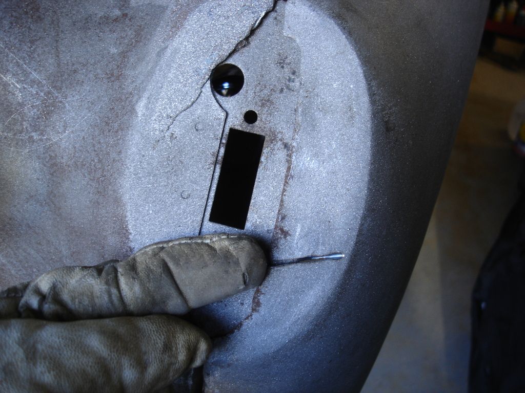
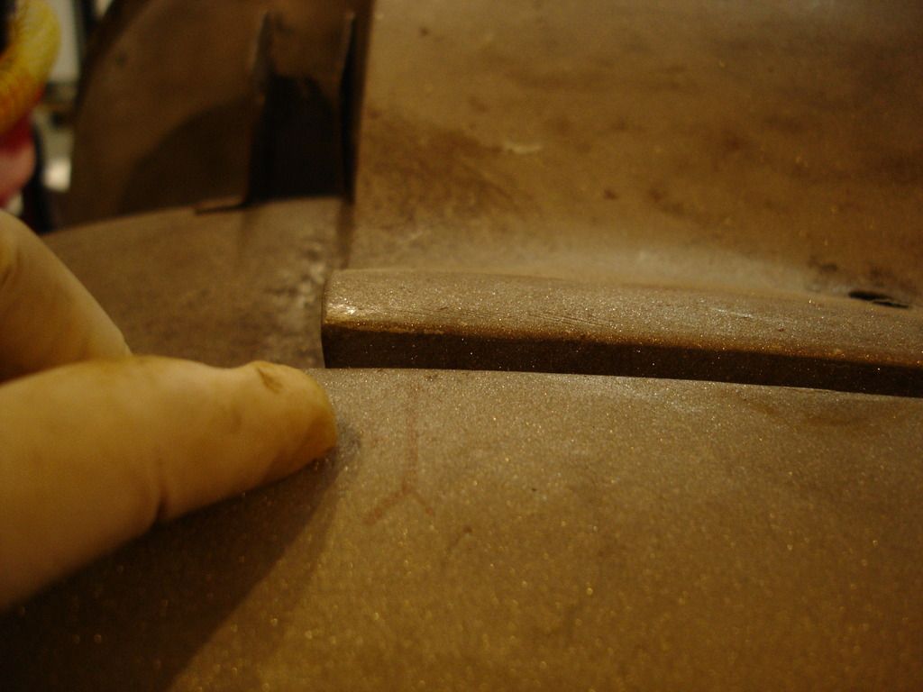
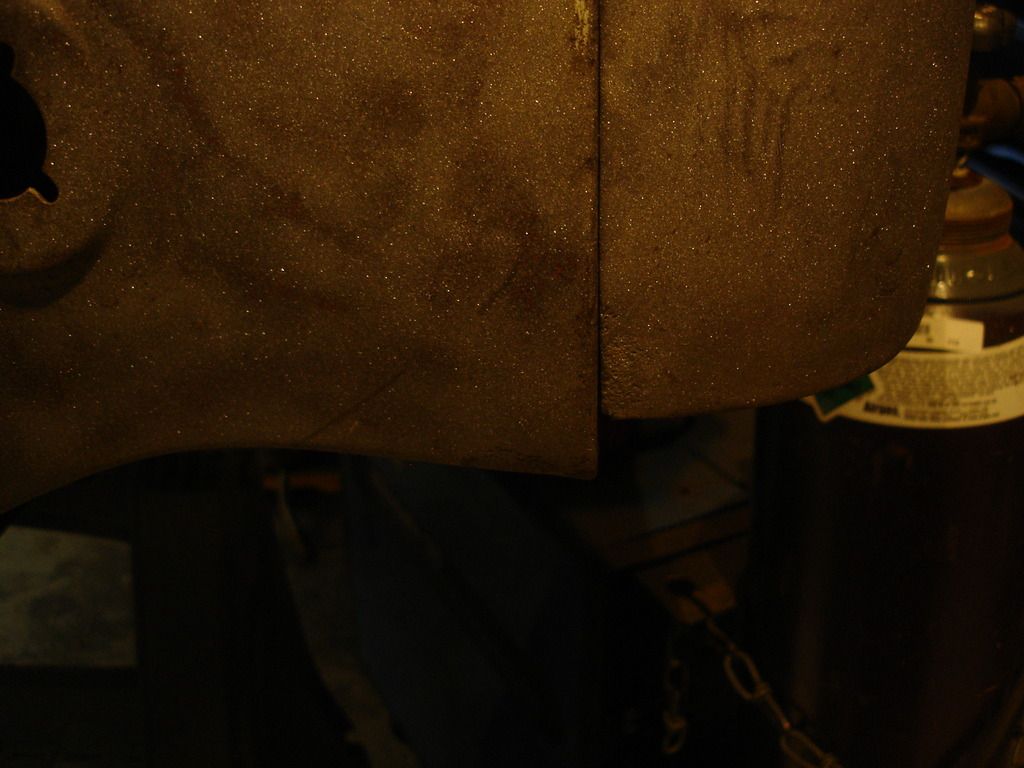
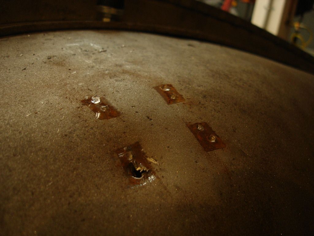
My right rear wing started to show some distress with all the hammering. There was a little spot where the tail light mounts that kept "popping" upward. Too much metal from the previous repairs! The usual technique would be to shrink it back to flat. I felt lazy at the end of the day, and not up to removing the 20 bolts holding the wing to work on it...so I sliced the bump, hammered it flat, and welded it back together. The trick was to weld in short bursts to prevent welding the wing to the tub. I'll find out later if I was successful or not?!?


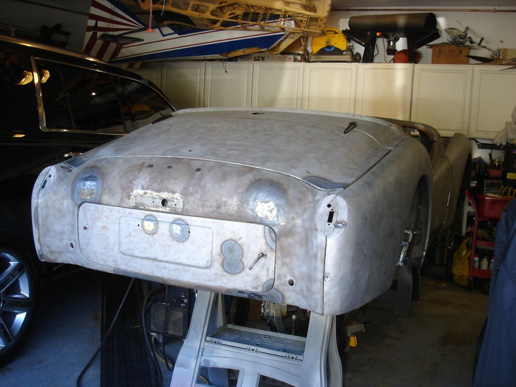
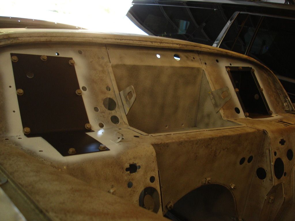
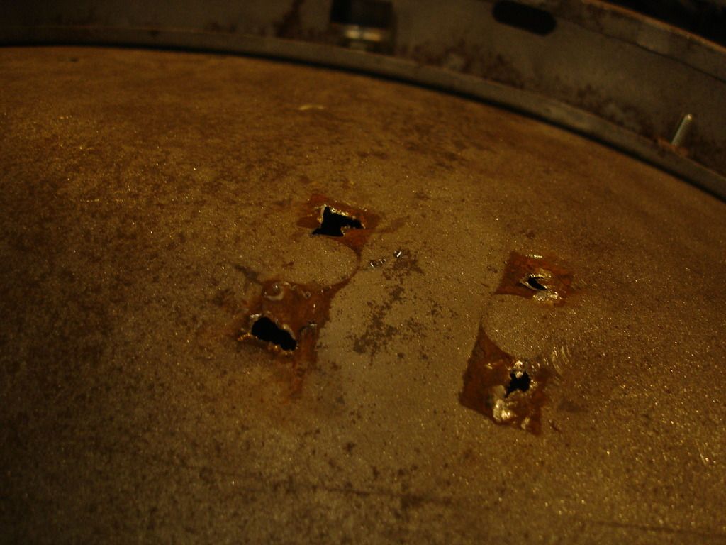
I'm now happy with the boot lid...and the right wing patch.

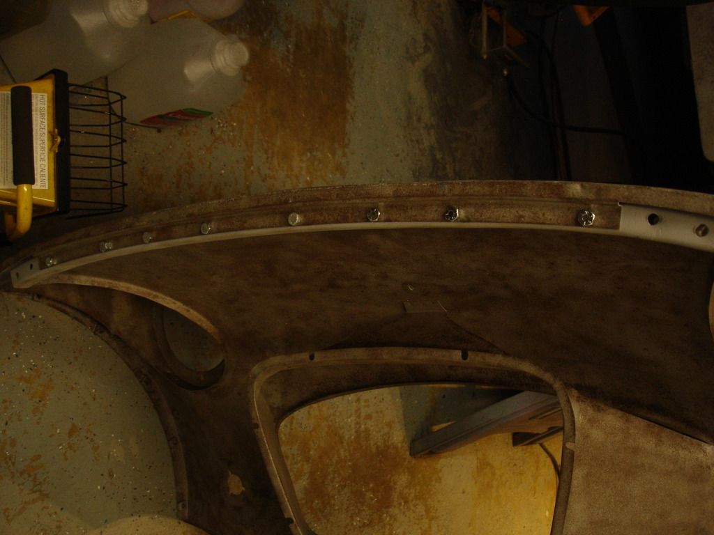
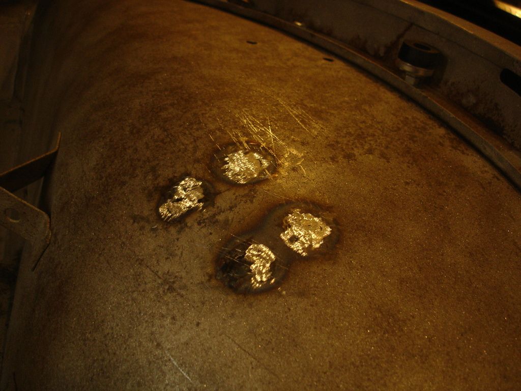
I spent several hours re-fitting the spare tire cover. No pics, but you'll notice it matches better than before. All a matter of sitting there checking, removing, hammering, rechecking...etc. It sits funny as it needs the seal to hold it in position properly. I am certain it will take more tweaking when I add the seal.


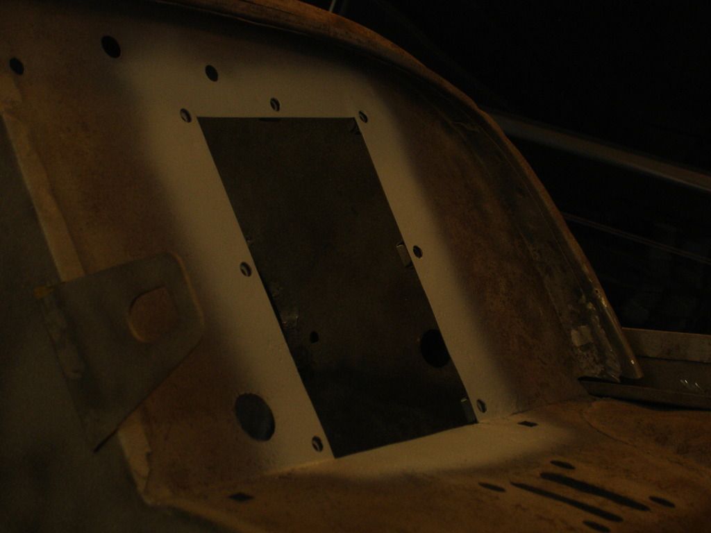
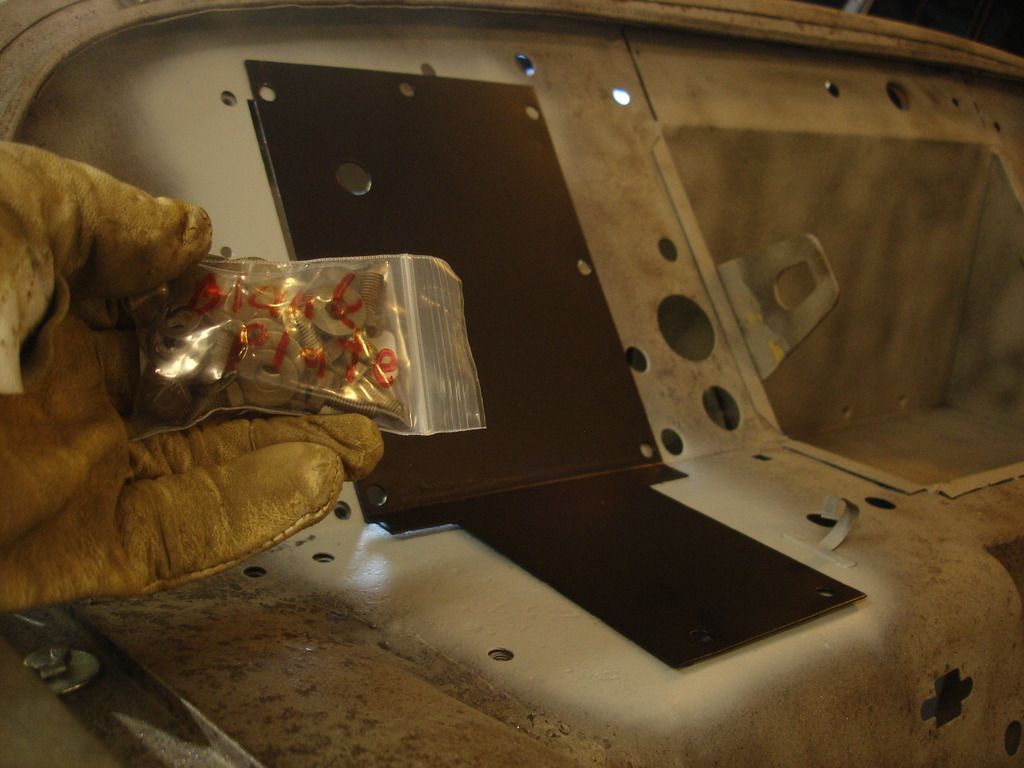
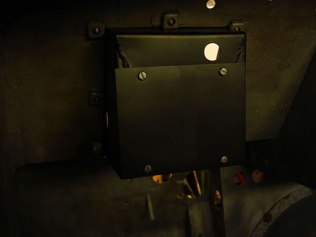
In preparation for the front valence and bonnet, I decided to install the blanking plate and pedal box to stiffen up the firewall. I primed the contact area, and will bolt them in place. The factory painted with these installed. I plan to do the same...so this will be the final installation of these parts...the first parts of their kind!


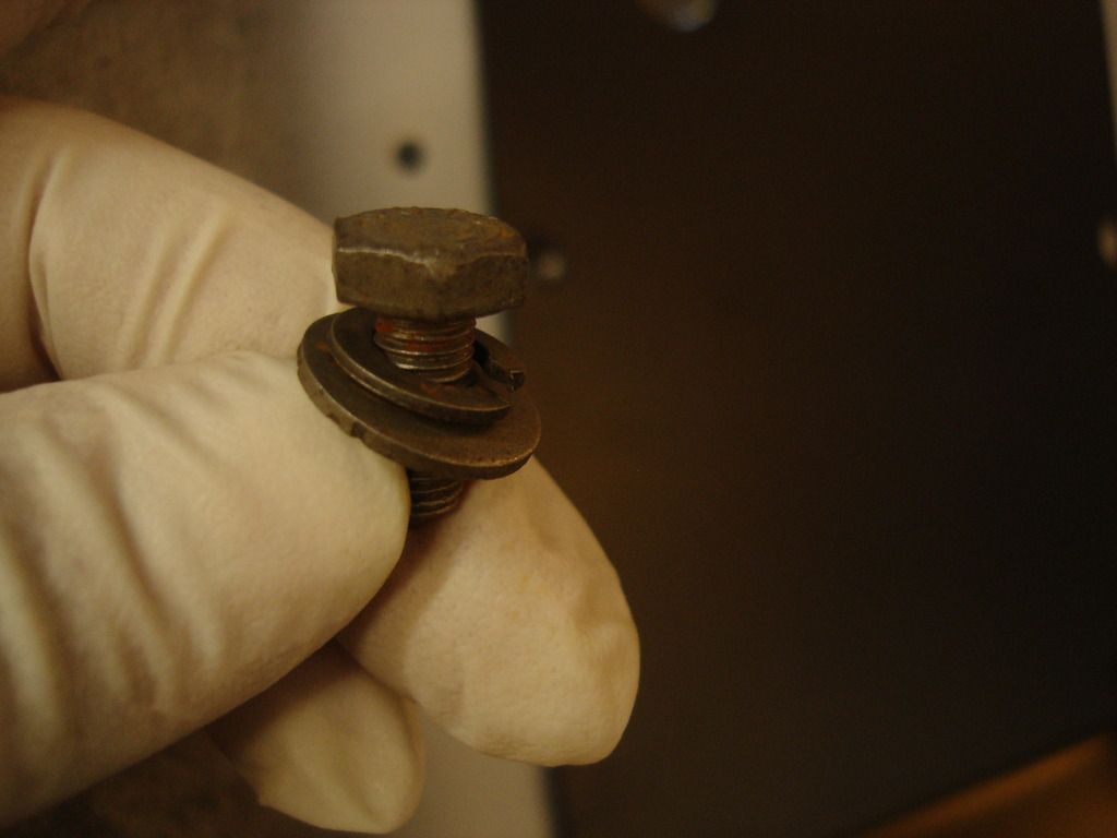
Funny...I primed and set aside the parts 3 years ago. We're into an archaeological timeline now!


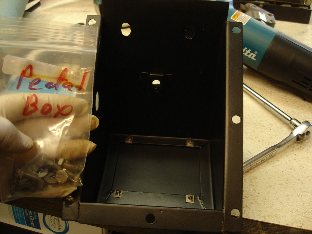
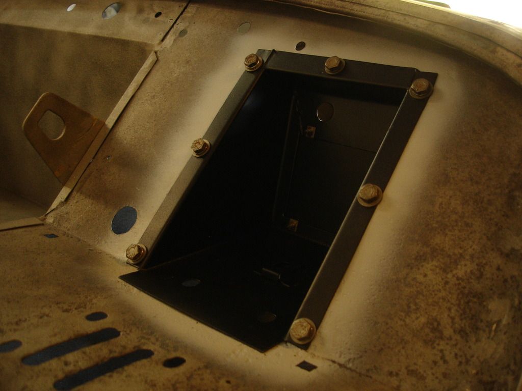
The first permanently installed body parts!!


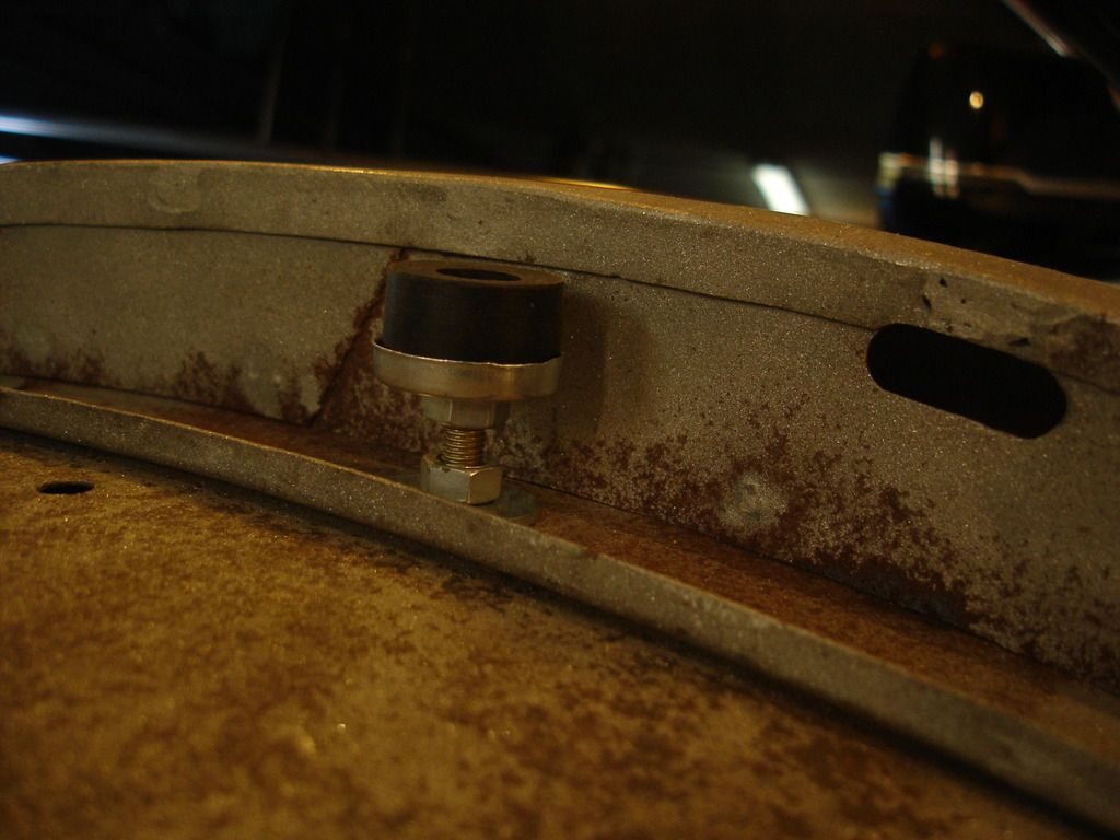
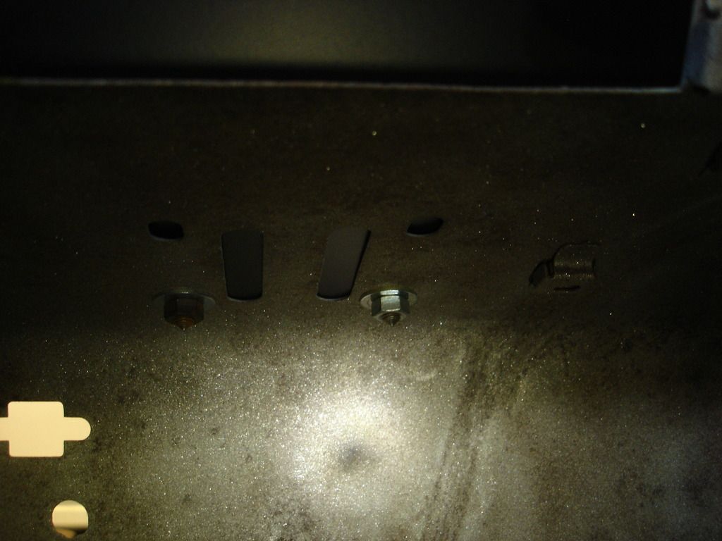
Getting ready for the valence and bonnet...the front bonnet bumpers go in the forward bolt positions.


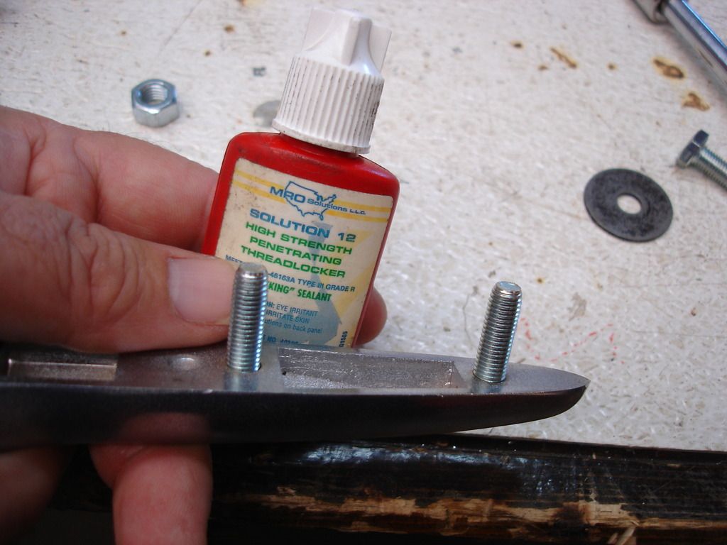
i prepped the hinges by lock titing in the studs. It's a pain when you have to remove the nuts 50 times and the studs keep coming out. Threading them in tightly is NOT an option, as the hinges are just pot metal and will not take much torque at all.


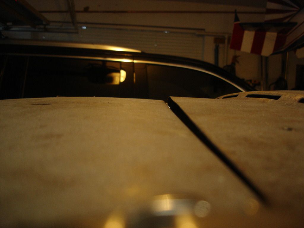
First bonnet fitting. Uhg. I realize that the bonnet fitting will try my patience to no end.


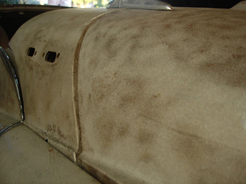
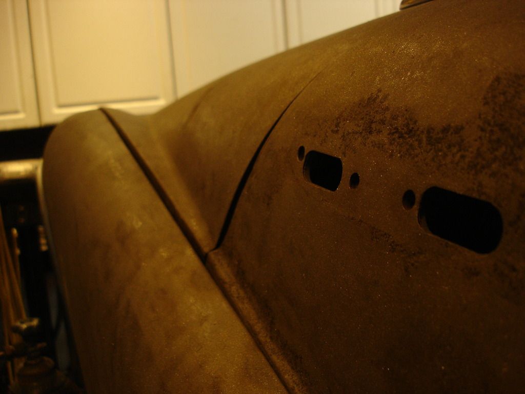
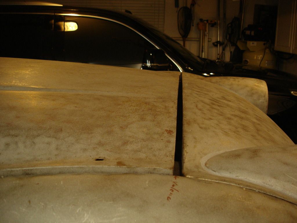
This is the upper rear edge of the bonnet. In the TR2's and early 3's, there is no rolled edge...just a bare straight edge. This edge has scared me from the first time I saw it...and now is the time to deal with it. The issue is that a straight 18 gage edge will never be stable. It is flimsy, and yet needs to align with the scuttle.


And the left fit...cringe!


This is the mark I placed on the wing to show where the front apron extends. I guess you see the problem here?!? The bonnet and apron are fighting for the space available. The only good thing I can say is I would rather too much metal than not enough. Let's remove the bonnet and start with the apron...


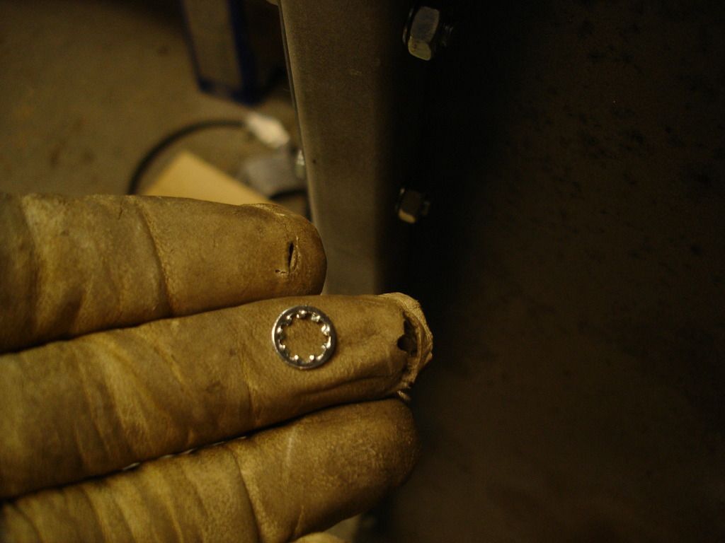
I installed the aluminum stiffner across the rear of the apron. These bolts use those little star lock washers. Now, a point of order...

Whenever a designer uses star lock washers, he is trying to tell you the doesn't want the bolts torqued tightly, but he still wants them to stay in place. You are torquing a thin metal edge to a thin aluminum bar. Barely more than finger tight is enough! Remember how much I had to straighten the metal tab last year? snug is good!


"Apron Ho!" The apron must align with the front bottom edge of the wings. So it will be installed backwards from the rear wings...start at the front and work back with the bolts. DO NOT tighten any of the out wing to inner wing bolts until the apron is set...the apron determines the spacing between the wings.


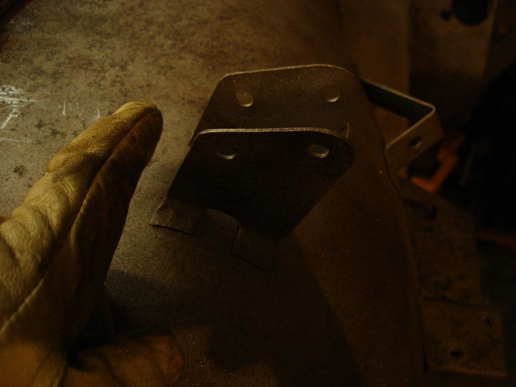
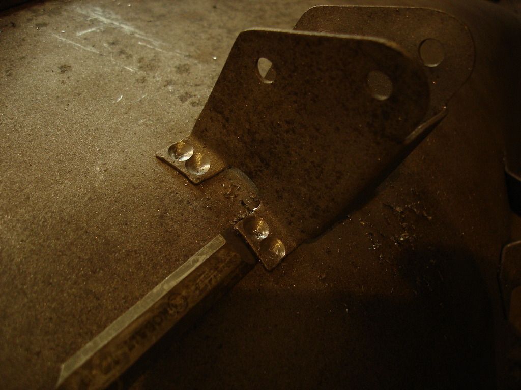
Next problem...this is the bracket that holds the aluminum apron bar at the back. It doesn't line up. Bummer. this will be a pain...


Uhgg!


Double ughh!!


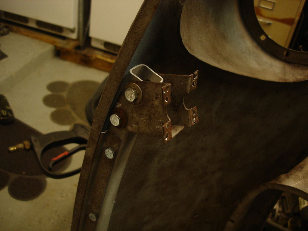
This is likely how the factory placed these brackets. It is mounted to the apron, and now the apron will be installed, allowing the bracket to find it's place on the inner wing.


1 hour later...

 
Last edited:


Now it's coming together. The apron can be aligned at the front, and then work back to the mounting brackets.


Once I was happy with the apron alignment, I re-welded the brackets in place.


Apron on and bonnet set where it will have to go. Now the problem moves to the rear edge of the bonnet.


Even with no gap up front, the bonnet sits about 1/4" too far rearward in the back.


Well, let's do the easy part first...making sure the hinge studs sit in the slots easily.


When the gap at the front is set, the bonnet rides up the firewall. This is going to be slow.


The corollary to the above is that the hinge holes do not align either.


The first step was to spend a couple hours taking measurements of all the slots and brackets to see where best to attack.


I needed to cut the corners to prevent the bonnet from riding up. Doing this allowed it to settle onto the scuttle, and better observe the areas to address.


Back here there are 2 things going on. The bonnet edge is long and uneven. Then, the scuttle is actually too low in the center. Both will need to be addressed.


With the corner cut, the bonnet settles in. I could now tap much of the rear edge to match it to the scuttle.


Next! Notice the bump at the hinge slots. That is the hinge reinforcement. This started innocuously, but turned into a real bear. I trimmed the reinforcement, only to find that then the bonnet rear bow was contacting the firewall rain gutter.

"Oh...the humanity!!!"

The only fix for the bow being too close to the rain gutter is to move the bow forward. Excuse me. I have to go cry.


I'm over it...back to work.

Not shown, I had to grind out the rear bonnet bow and move it forward about 3/8". 3/8"...sounds so small, but in bodywork it may as well have been a mile. But, with the bow trimmed, the fitting could be continued.

This is the trimmed left rear corner. I began making small adjustments, like this...gradually working to the final fit.


I have to get rid of the extra metal back here. To measure it, I primed the rear edge, to mark it's current location.


Now I made marks every few inches with numbers. Now, when the bonnet is moved, I can measure the overlap on the left, and transfer the measurement to the bonnet on the right. Once I know how much, it's just a matter of using the tin snips.


Oh...I did set the front gap using 1/8" stirring sticks while I took the measurements a the rear.

At this stage I had to stabilize the rear edge of the bonnet that was flapping around. I decided to use a non-standard technique, for lack of any other idea...


Here I am pushing the metal into place along the rear bonnet bow, and then tacking the sheet metal to the bow at the available holes...i.e. the hinge slots. This will stabilize the metal so it cannot slide back and forth.


I then repeated the technique farther inboard, at the rivet holes.


A little closer...


And closer...

This is where I had to stop for the week. I foresee at least 2 more days in just fitting the bonnet. Then, several more days fine tuning all the gaps once the hammering is over. A good week's work, but still a long way to go...
 
It's looking awesome John. You do fabulous work.

Thanks so much for taking the time to photograph and document your work here for us. I know how much effort it takes and I for one really appreciate you going the extra mile.

Cheers
Tush
 
Thanks Dave. It's nice to finally get to see a car. 4 years of working on single parts got really old...no way to visualize the end.

I just got word I'm changing equipment at work. It means I'll switch from a fixed schedule to reserve. After a month of every day training, the reserve should give me many, many more days per month to work on the Triumph. Enough that I can visualize driving this bad boy by summer.

Thanks again for showing support. It means a lot from one who has the courage to restore so many Triumphs!
 
I understand most of it. John you have opened my mind to more and more possibilities. I need to practice my welding to get the freedom you have with metal. I thought those nipped bolt holes were done by unexperienced body men too, no I see. I would like to ask-- it looks like you used the later fenders with the slotted bolt holes for the apron bolt holes, so is the front the clip and inner fenders later also?

Clearly you have been one of my best teachers, and with respect, but it looks to me like I should bolt the front fenders to the apron and leave the aluminum tie piece off until I see what is going on with a front end and then pull downwards the 3 front end piece to fit the hood, or slid the apron up and down. But again I have never seen a tr2 hood that close, or again is that why you took a break.
 
Now I'm getting worried...you're catching everything!

You're right about the slotted front wing. My car was smashed badly at some point on the left front, and when I got it the front wing had been replaced with a later, slotted version. I considered welding the slots back to the TR2 "round" shape...but decided it was a lot of work that nobody would notice...except you!

Your idea to tackle the front metal is also very valid. With a newer bonnet that has the rear lip rolled into it, it would likely be less effort to fit the apron to the bonnet, and then adjust the lower, front of the wings and apron to be even. That's the way I did my TR3...easier to fix the wing length over a few inches versus re-bending 5 feet on the rear edge of the bonnet.

In my case, I had previously matched the apron to the wings, and adjusted the mounting holes for alignment at the front. I had no way on the bench to know that I had too much length overall. The rear edge of the early bonnet can be easily trimmed to fit, compared to either adding or removing from the wings. But...sometimes you pick a fix that looks easiest at the time, only to find it was more work in the end. That's the nature of bodywork. Occasionally a better fix becomes glaringly obvious...only too late!

If I had realized I was going to have to relocate the bonnet rear bow, I would have chosen to lengthen the wings instead. But, by the time I did realize the bow was going to have to move, I had already trimmed the bonnet length. More work after all. It's also possible that the same PO that shortened the rear wing also shortened the front wings...so I chose the wrong solution entirely. But, the entire "fix" is only about 1/4-3/8". It will work out in the end, with all the parts matching each other.

The front apron bow has a little adjustment to it...say 1/8 to 1/4", by tapping the apron flange and/or the mounting bracket. If mine was not off as far as it was, it could have been dealt with by tapping with the bracket still in place. If you remember, the front of my car was a mess...


I'm happy it came out as closely as it did after the wreck, previous poor patching, and then the re-patching. Most cars would not be as extreme, and not require adjusting brackets and such.

I think it's really cool that you have reached the point where you can "see" all the possibilities you have in a project. There is no wrong way, only some ways that are more work than others!
 
The work is amazing John and I am very happy you took the time to share. The work has made me a better craftsman and I am very grateful. Creating a tr2 out of all that is something I did not think possible by one guy in the time you did it, my hat if off.
 
If I can get half as close as this car will look I will be thrilled. You have an amazing eye for detail. I will have a lot to reference when I get back to my project. I am still enjoying the addition with the extra garage space and trying to thin out the crap.

Thanks for the pictures it really help to visualize the process.
 
Rich, got your pm. But it won't let me pm back until you join...

Which measurement on the wing do you need?
 
Sorry John, but I am back to making the wing patch. So John when you bent the ½ inch 90 degree on the bottom that is about a foot long, did you heat the metal up and use your vise grips on the anvil to get that nice fold, or do you have a sheet metal break, or ?
 
I use 2 pieces of angle iron (cold rolled so it is smooth) clamped in my vice and "C" clamps to hold one side then bend it over with a wooden block followed up with a hammer. I filed a small radius on one piece of angle so that I get a better bend.

David
 
Yeah John I hope soon I am trying to figure out the best way to replace my cheesy welder with a better unit. I have most of the garage sorted and think I may try to get the blue Tr3 unit to turn over but I am missing some linkage pieces on the Su carbs! We have a GYHD (get your hands dirty ) event in feb for the club to come by and give me a hand doing just that! Gotta pick up a garage heater first! But all the parts are here soooo
 
Back
Top